EP1518633B1 - Procédé de soudage et article assemblé - Google Patents
Procédé de soudage et article assemblé Download PDFInfo
- Publication number
- EP1518633B1 EP1518633B1 EP04022609A EP04022609A EP1518633B1 EP 1518633 B1 EP1518633 B1 EP 1518633B1 EP 04022609 A EP04022609 A EP 04022609A EP 04022609 A EP04022609 A EP 04022609A EP 1518633 B1 EP1518633 B1 EP 1518633B1
- Authority
- EP
- European Patent Office
- Prior art keywords
- weld
- welding
- laser
- heat conduction
- cavity
- Prior art date
- Legal status (The legal status is an assumption and is not a legal conclusion. Google has not performed a legal analysis and makes no representation as to the accuracy of the status listed.)
- Expired - Lifetime
Links
- 238000003466 welding Methods 0.000 title claims abstract description 96
- 238000000034 method Methods 0.000 title claims abstract description 54
- 238000010894 electron beam technology Methods 0.000 claims abstract description 14
- 239000000779 smoke Substances 0.000 claims abstract description 8
- 239000000463 material Substances 0.000 claims description 9
- 239000000945 filler Substances 0.000 claims description 6
- 230000035515 penetration Effects 0.000 claims description 5
- 230000000284 resting effect Effects 0.000 claims description 5
- 230000000295 complement effect Effects 0.000 claims description 2
- 239000000843 powder Substances 0.000 claims description 2
- 230000002093 peripheral effect Effects 0.000 claims 4
- 239000007787 solid Substances 0.000 claims 3
- 239000003518 caustics Substances 0.000 claims 1
- 239000003517 fume Substances 0.000 claims 1
- 239000007769 metal material Substances 0.000 claims 1
- 238000007789 sealing Methods 0.000 claims 1
- 230000008021 deposition Effects 0.000 abstract description 3
- 230000015572 biosynthetic process Effects 0.000 abstract description 2
- 239000011796 hollow space material Substances 0.000 abstract 1
- 210000002414 leg Anatomy 0.000 description 29
- 238000009826 distribution Methods 0.000 description 22
- 238000012545 processing Methods 0.000 description 6
- 230000001154 acute effect Effects 0.000 description 5
- 238000003754 machining Methods 0.000 description 5
- 238000004519 manufacturing process Methods 0.000 description 5
- 239000002131 composite material Substances 0.000 description 4
- 230000000694 effects Effects 0.000 description 4
- 239000002245 particle Substances 0.000 description 4
- 238000013461 design Methods 0.000 description 3
- 238000011161 development Methods 0.000 description 3
- 230000018109 developmental process Effects 0.000 description 3
- 238000005516 engineering process Methods 0.000 description 3
- 238000004140 cleaning Methods 0.000 description 2
- 239000007789 gas Substances 0.000 description 2
- 239000007788 liquid Substances 0.000 description 2
- 229910000831 Steel Inorganic materials 0.000 description 1
- 238000010521 absorption reaction Methods 0.000 description 1
- 239000011324 bead Substances 0.000 description 1
- 238000010276 construction Methods 0.000 description 1
- 238000011109 contamination Methods 0.000 description 1
- 238000005520 cutting process Methods 0.000 description 1
- 208000018459 dissociative disease Diseases 0.000 description 1
- 230000017525 heat dissipation Effects 0.000 description 1
- 238000010438 heat treatment Methods 0.000 description 1
- 230000000670 limiting effect Effects 0.000 description 1
- 239000000155 melt Substances 0.000 description 1
- 230000008018 melting Effects 0.000 description 1
- 238000002844 melting Methods 0.000 description 1
- 239000002184 metal Substances 0.000 description 1
- 239000000203 mixture Substances 0.000 description 1
- 230000003287 optical effect Effects 0.000 description 1
- 230000001681 protective effect Effects 0.000 description 1
- 230000005855 radiation Effects 0.000 description 1
- 230000002829 reductive effect Effects 0.000 description 1
- 239000011265 semifinished product Substances 0.000 description 1
- 238000007711 solidification Methods 0.000 description 1
- 230000008023 solidification Effects 0.000 description 1
- 125000006850 spacer group Chemical group 0.000 description 1
- 230000003068 static effect Effects 0.000 description 1
- 239000010959 steel Substances 0.000 description 1
- 238000012549 training Methods 0.000 description 1
- 210000000689 upper leg Anatomy 0.000 description 1
Images

Classifications
-
- B—PERFORMING OPERATIONS; TRANSPORTING
- B23—MACHINE TOOLS; METAL-WORKING NOT OTHERWISE PROVIDED FOR
- B23K—SOLDERING OR UNSOLDERING; WELDING; CLADDING OR PLATING BY SOLDERING OR WELDING; CUTTING BY APPLYING HEAT LOCALLY, e.g. FLAME CUTTING; WORKING BY LASER BEAM
- B23K15/00—Electron-beam welding or cutting
- B23K15/0033—Preliminary treatment
-
- B—PERFORMING OPERATIONS; TRANSPORTING
- B23—MACHINE TOOLS; METAL-WORKING NOT OTHERWISE PROVIDED FOR
- B23K—SOLDERING OR UNSOLDERING; WELDING; CLADDING OR PLATING BY SOLDERING OR WELDING; CUTTING BY APPLYING HEAT LOCALLY, e.g. FLAME CUTTING; WORKING BY LASER BEAM
- B23K15/00—Electron-beam welding or cutting
- B23K15/0046—Welding
- B23K15/0053—Seam welding
- B23K15/0073—Seam welding with interposition of particular material to facilitate connecting the parts, e.g. using a filler
-
- B—PERFORMING OPERATIONS; TRANSPORTING
- B23—MACHINE TOOLS; METAL-WORKING NOT OTHERWISE PROVIDED FOR
- B23K—SOLDERING OR UNSOLDERING; WELDING; CLADDING OR PLATING BY SOLDERING OR WELDING; CUTTING BY APPLYING HEAT LOCALLY, e.g. FLAME CUTTING; WORKING BY LASER BEAM
- B23K26/00—Working by laser beam, e.g. welding, cutting or boring
- B23K26/20—Bonding
- B23K26/21—Bonding by welding
- B23K26/24—Seam welding
-
- B—PERFORMING OPERATIONS; TRANSPORTING
- B23—MACHINE TOOLS; METAL-WORKING NOT OTHERWISE PROVIDED FOR
- B23K—SOLDERING OR UNSOLDERING; WELDING; CLADDING OR PLATING BY SOLDERING OR WELDING; CUTTING BY APPLYING HEAT LOCALLY, e.g. FLAME CUTTING; WORKING BY LASER BEAM
- B23K26/00—Working by laser beam, e.g. welding, cutting or boring
- B23K26/60—Preliminary treatment
-
- B—PERFORMING OPERATIONS; TRANSPORTING
- B23—MACHINE TOOLS; METAL-WORKING NOT OTHERWISE PROVIDED FOR
- B23K—SOLDERING OR UNSOLDERING; WELDING; CLADDING OR PLATING BY SOLDERING OR WELDING; CUTTING BY APPLYING HEAT LOCALLY, e.g. FLAME CUTTING; WORKING BY LASER BEAM
- B23K33/00—Specially-profiled edge portions of workpieces for making soldering or welding connections; Filling the seams formed thereby
- B23K33/004—Filling of continuous seams
Definitions
- the invention relates to a method for welding at least two preferably metallic components by means of an energy beam, preferably a laser beam, along a weld joint, and a body composed of at least two components, preferably a hollow body, which is preferably produced by the above-mentioned method, and the use of a laser system for producing such a composite body.
- a distribution ring for dispensing liquids in bottles.
- a distribution ring has a diameter of up to 6 m and has a circumferential distribution channel, which is formed as a hollow channel with a plurality of openings. The openings are connected to supply and discharge lines or with valves. When filling bottles, the liquid is introduced into the distribution channel and passed through the valves in the bottles.
- the distribution channel is formed by a radially encircling, rectangular in cross-section groove in the Verteilerringoasa and welded onto the Verteilerring Sciences as a cover for the groove band.
- the welding of cover strip with the distributor ring body is carried out in the known methods via a multi-layer TIG welding at a welding speed of about 100 mm / min.
- the multi-layered weld is required to the connection cross-section between the band and the actual distribution ring load-carrying, as occur during operation in the distribution channels large pressures.
- This known manufacturing method for distributor rings has as significant drawbacks that the processing time for welding the bands on the distributor ring body is very long and that the distributor ring warps by the heating during the long welding operation.
- the weld joint has not been completely melted, in particular in the region of the cavity of the distributor channel, so that gaps left in the foot region of the weld joint between the lid and the ring remain open to the cavity. These gaps prevent effective cleaning of the distribution channel, as dirt particles can accumulate in the gaps. Furthermore, under load, the notch effect occurring through the gaps can lead to a failure of the laser weld seam.
- a further problem has been recognized that the cavity is heavily contaminated by the spatter caused by the laser beam deep welding and to the cavity - ie to the distribution channel - open steam capillary, as spilled by the Dampfkapillare spatter, smoke and smoke.
- housings for electrical switchgear are constructed in plate construction. In the manufacture of the housing laser welding is used today for connecting the plates. To prevent that in the Housing internal welding emissions occur, the weld at an acute angle to the joint, often preferably 5 °, introduced. The penetration of emissions into the housing interior can not be reliably prevented in this way.
- the weld joint opens a joint open to the side facing the welding head and one in the region of Has foot of the joint arranged abutment area in which the components abut each other and which closes the weld joint on the side facing away from the welding head, wherein in a first process step, the binding partners are connected in the investment area by thermal conduction welding to form a heat conduction weld and in a second process step the binding partners in Area of the joint and along the heat conduction weld by laser beam or electron beam welding, preferably laser beam or electron beam deep welding, are connected, wherein the heat conduction weld ve prevents process emissions, in particular spatter, smoke or smoke from escaping at the inside of the workpiece during laser beam or electron beam welding.
- the workpieces to be joined are preferably made of metal, but may also consist of plastic or other materials.
- a laser system for generating the energy beam, preferably a laser system, in particular a Nd: YAG, diode or CO 2 laser system, is used, but in modified embodiments of the method, electron beam welding systems can also be used to generate the energy beam.
- the workpieces i. the components to be joined are arranged abutting one another, wherein between the workpieces to be welded joint - the weld joint - is formed.
- the weld joint is welded in the later process steps in the longitudinal direction, ie along the longitudinal extent.
- the weld joint comprises a joint open to the side facing the welding head and a contact region connected to the lower end, ie opposite the opening of the joint, in which the two components to be welded abut each other, ie are in contact with each other. This contact area ends at the workpiece inside.
- the energy beam of the contact region which preferably enters through a gap which is opened through the side facing the welding head is preferably completely welded, so that a heat conduction weld is formed at the location of the contact region.
- the same section of the weld joint is again passed over by an energy beam as in the case of heat conduction welding, wherein the components in the region of the joint are preferably connected by heat conduction or deep welding.
- the heat conduction weld produced during the first process step prevents the vapor capillary formed in the second process step in the case of deep welding from opening to the inside of the work piece and prevents process emissions, in particular spatter, smoke or smoke from escaping from the inside of the work piece.
- the resulting during deep welding vapor capillary is in the direction of the side facing away from the welding head, ie. preferably the workpiece inside limited by the heat conduction weld.
- the method is advantageously carried out when the energy beam is supplied from the workpiece outside. This is the case, for example, when the energy beam enters through the gap open to the workpiece exterior.
- the material mis-volume of the weld joint in the region of the joint can be filled either by melting the material of the material in contact with the excess material or by additional material, preferably powder, filler wire, etc.
- the filler material can be either automatically fed during welding or inserted as a filler before the second step in the joint.
- the method is advantageously formed when the heat conduction welding process is performed so that the weld joint on the side facing away from the welding head by the heat conduction weld, i. preferably the workpiece inside is sealed. This is the case in particular if a uniform, smooth welding bead is produced on the underside of the workpiece by the heat conduction welding.
- the seal prevents dirt particles from escaping from the weld joint to the inside of the workpiece.
- the heat conduction welding process when the heat conduction welding process is performed so that at the side facing away from the welding head side, preferably the workpiece inside a gap-free and / or concave surface is formed.
- a gap-free and / or concave surface is formed.
- Such a design of the surface reduces the notch effect and prevents the deposition of dirt particles on the side facing away from the welding head side of the workpiece, ie preferably the workpiece inside.
- the formation of the heat conduction weld on the relevant workpiece side, ie preferably workpiece underside can by the use of suitable Formiergasen -. As He, Ar, H 2 , N 2 or mixtures of these gases - be supported.
- This training can be achieved by a bevel, rounding or grading of one or both workpieces or a chamfer at one or both workpieces in the region of the weld joint.
- the V-shaped joint may have an opening angle between 15 and 45 °, preferably between 20 and 40 ° and in particular between 25 and 35 °, wherein the information is based on a full angle.
- the full opening angle should be greater than the Kaustikwinkel of the incident laser beam, so that the laser beam can penetrate without too much absorption at the joint walls into the investment area.
- the joint may be formed substantially rectangular in cross section, wherein preferably the diameter of the laser beam in the initial region of the joint is smaller the width of the joint is formed.
- the abutment region that is to say the contact region between the workpieces, is of planar design.
- This flat contact area is dimensioned in its dimensions so that it is completely melted during heat conduction welding.
- it is provided to design the impact geometry such that the masses of the workpieces adjacent to the abutment region are distributed in such a way that the heat dissipation from the abutment region into the workpieces is approximately the same for both workpieces.
- the method is used to join two workpieces forming a cavity with the workpiece inside facing the cavity.
- the cavity may be a completely closed or a multi-apertured and / or apertured cavity.
- the method also finds application for the connection of workpieces, wherein the welding impact from one side, in particular the workpiece inner side, is difficult or impossible for the energy beam.
- the method for the production of a distribution ring of the type described above can be used, which consists of a distributor ring body with circumferential groove and a band, wherein the tape is welded to close the groove on the distributor ring body.
- the distribution ring may also have multiple distribution channels.
- the object underlying the invention is further achieved with the composite of several components body according to claim 15.
- it may be a cavity body consisting of a body and a lid which together form a cavity and interconnected with at least one laser weld assembly, the laser weld assembly extending continuously from the outside of the cavity body to the cavity, the laser weld assembly preferably from a heat conduction weld and a deep weld, and wherein it is provided that the heat conduction weld is formed adjacent to the cavity and the deep weld is limited by the heat conduction weld to the cavity.
- the laser weld seam arrangement is designed as a juxtaposition of a first and a second weld seam, preferably a heat conduction weld seam and a deep weld seam, wherein the laser weld seam assembly begins with the deep weld seam in the case of the hollow body on the outside of the hollow body.
- the heat pipe weld Directly connected to the deep weld is the heat pipe weld, which immediately adjoins the cavity of the cavity body with its end portion.
- the deep welding effect and thus the production of the deep weld is achieved by forming a vapor capillary.
- the penetration depth is greater than or equal to the penetration depth of the vapor capillaries.
- the laser radiation is absorbed on the walls of the vapor capillary. The result is a steam bath surrounding the melt bath, which forms the deep weld after solidification.
- the deep weld penetrates the heat weld, but does not penetrate it completely.
- the concave surface very effectively prevents deposition of dirt particles and facilitates cleaning of the cavity. Furthermore, the concave surface reduces the notch effect at the joint by attacking forces.
- the cavity body is a distribution ring of the type described above.
- the laser system preferably has a guiding machine, in particular a Cartesian guiding machine or a robot, relative to the welding head to move the workpiece precisely guided.
- a guiding machine in particular a Cartesian guiding machine or a robot
- the welding head or alone the workpiece or both can be moved.
- the tensioning means may be static tensioning means, e.g. Clamping jaws, or dynamic clamping means, e.g. Pressure rollers or Antikfinger, which are moved with the energy beam act.
- the laser system has a laser aggregate, which is preferably formed from a CO 2 or Nd: YAG laser or a diode laser or a CO 2 laser with an output power of more than 1,000 watts.
- this has a shock-tracking sensor, which senses the position of the weld joint.
- the sensor can be designed as an optical - in particular as a light section sensor - or as a tactile sensor.
- the measured sensor values are either on-line, i. during ongoing processing, or off-line, i. Before machining, they are offset against a programmed machining path or form the basis for creating a machining path.
- FIG. 1 shows a U-profile 2, which is closed in longitudinal extension by an applied cover band 4, so that a cavity body 1 is formed with a rectangular cavity 3.
- the hollow body 1 is in FIG. 1 shown in the unwelded state.
- the U-profile 2 consists of a rectangular base body, to which two mutually parallel and mutually mirror-symmetrical legs 5 are arranged, wherein the base body and legs 5 in the illustration in FIG. 1 to form a standing U.
- Modified U-profile body with asymmetrical legs for example with different lengths and / or unparallel legs are conceivable.
- the U-profile may be formed as a one-piece, preferably extruded or exciting manufactured one-piece body or as a multi-part composite body.
- the two legs 5 have at their directed to the cavity 3 inner sides in each case a step with a horizontal, parallel to the bottom of the cavity 3 aligned support shoulder 6.
- the support heels 6 are arranged on the legs 5 opposite at the same height.
- the adjoining the support heels 6 leg end portions are each bevelled on the inside to form a chamfer 7.
- the chamfers 7 are aligned divergently from each other. Between the chamfer 7 and the support shoulder 6 an obtuse angle alpha of about 120 ° is formed in each case.
- the chamfer 7 joins each directly to the support shoulder 6 to form an edge 22 and extends to the distal end of the leg. 5
- the cover strip 4 is rectangular in cross section and is lying on the receiving heels 6 of the U-profile 2, wherein the inner sides of the U-shaped profile 2 and the underside of the cover strip 4 form the rectangular cross-section cavity 3.
- the edge regions of the underside-that is, the side facing the cavity 3 -the cover strip 4 and the support heels 6 of the U-profile 2 are in surface contact with one another.
- the cover band 4 rests on both sides supported on the support heels 6, wherein the left lower edge of the cover strip 4 close to the edge 22 of the left support portion 6 and the right lower edge of the cover strip 4 is close to the edge 22 of the right support paragraph 6.
- the tolerance for the width of the cover strip is determined by the width of the support paragraph. The width may not exceed the distance between the edges 22 to each other.
- the minimum dimension of the lid width is calculated from the width of the cavity plus the width of the support paragraph 6 plus about 0.2 mm.
- a V-shaped joint 8 between the narrow sides of the cover strip 4 and the chamfers 7 is formed with inserted cover strip 4 respectively.
- This gap 8 is to the outside of the cavity body 1 in FIG. 1 formed to be larger at the top and has an acute opening angle gamma of about 30 ° in cross-section.
- the V-shaped joint is closed by laser deep welding in a second processing step. In both processing steps, the laser beam is radiated from the cavity body outside in the joint 8.
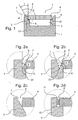
- FIGS. 2a-2d be alternative embodiments for the impact geometry in FIG. 1 explained.
- the detail is shown, the detail A in FIG. 1 corresponds, and essentially represents the weld.
- FIG. 2a shows a first modified embodiment of the detail A in FIG. 1 , It is a leg 5 and a resting on a support shoulder 6 of the leg 5 cover band 4 is shown, wherein between legs 5 and cover band 6, a gap 8 is formed.
- the gap 8 is similar to the fugue in FIG. 1 V-shaped, but deviating from it is formed as follows:
- the leg 5 only has a rectangular recess.
- the chamfer 7 on the leg 5 in FIG. 1 is on the thigh 5 in FIG. 2a unavailable.
- the rectangular recess comprises a support shoulder 6, which analogous to the execution in FIG. 1 is aligned parallel to the bottom of the cavity 3, and a directly connected to the support shoulder 6 vertical section.
- the cover band 4 in FIG. 2a is contrary to the execution in FIG. 1 in the longitudinal direction in each case laterally beveled by a chamfer 7 ', so that an acute angle beta of approximately 60 ° is formed in the cross section between the underside and the narrow side of the cover strip 4.
- the joint 8 is formed with the cover strip 4 lying on the support shoulders 6 between the vertical section of the rectangular recess of the leg 5 and the bevelled side of the cover strip 4.
- the joint has an acute opening angle gamma of about 30 °.
- FIG. 2b shows a second modified embodiment of the detail A in FIG. 1 , wherein the leg 5 as in the embodiment in FIG. 1 is formed with a support shoulder 6 and with a chamfer 7 with an angle alpha.
- the cover strip 4 has as in the embodiment in FIG. 2a a chamfer 7 'with an angle beta.
- the angle alpha is approximately 100 ° and the angle beta is approximately 80 °.
- the joint 8 is formed when resting on the support heels 6 cover band 4 between the chamfer 7 of the leg 5 and the chamfer 7 'of the cover band 4.
- the joint has an acute opening angle gamma of about 20 °.
- Figure 2c shows a third alternative embodiment of the detail A in FIG FIG. 1 on, wherein the leg 5 has only one bevel 7 but no step.
- the chamfer 7 essentially corresponds to the chamfer 7 in FIG FIG. 1
- the cover band 4 is in Figure 2c in the Cross-section rectangular and lies with its lower longitudinal edge on the chamfer 7 of the leg 5 linear.
- the gap 8 is formed between the chamfer 7 of the leg 5 and the narrow side of the lid band 4.
- the overlying edge portion of the cover strip 4 may be flattened with a chamfer which is complementary to the chamfer 7 of the leg 5 formed on this resting.
- Figure 2d shows a further embodiment of the detail A in FIG. 1 , with the gap 8 in Figure 2d is formed in cross-section substantially rectangular.
- the leg 5 has as in FIG. 2a a rectangular recess with a vertical portion and with a horizontal support shoulder 6, wherein the support shoulder 6 with respect to the embodiment in FIG. 2a is widened.
- the cover strip 4 has a substantially rectangular cross section and rests with its edge region on the support shoulder 6.
- the joint 8 is formed when resting on the support heels 6 cover band 4 between the vertical portion of the rectangular recess of the leg 5 and the narrow side of the cover strip 4.
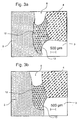
- FIGS. 3 a, b, c each show a schematic cross-section of the detail A in FIG Figure 1 or 2a-2d shown portion of the cavity body 1 after the thermal conduction welding by means of a Nd: YAG laser.
- the position of the heat conduction weld 12 corresponds to the position of the contact surface of the cover strip 4 on the leg 5 in the Figures 1 and 2 ad ,
- the surface of the heat conduction weld 12 is concave, so that a groove-like groove 13 is formed.
- the groove 13 merges in its edge regions into the underside of the cover strip 4 or into the inner surface of the leg 5.
- the joint 8 facing surface of the heat conduction weld 12 is also concave.
- Lid strip 4 and legs 5 have only a small connection cross-section, since the majority of the V-shaped joint 8 is still virtually unchanged after heat conduction welding and is unfilled.
- the concave surface shape is formed automatically due to surface tensions during and after heat conduction welding, respectively.
- the machining parameters for the three machining examples are shown in the following table.
- FIG. 4 shows a transverse section of the substantially same section as the FIGS. 3a-3c after re-welding the heat conduction weld 13 with a deep weld using a Nd: YAG laser.
- additional material in the form of filler wire was supplied during deep welding and the V-shaped joint was completely filled with a single weld.
- Lid strip 4 and legs 5 are in FIG. 4 connected via a connection cross-section which corresponds approximately to the thickness of the cover strip.
- the entire weld can be divided into two areas:
- the lower region comprises the heat conduction weld 12, which is arranged adjacent to the cavity 3.
- the heat conduction weld 12 has even after the second Koch facedung a groove 13 as in the Figures 3 ac on.
- the upper portion of the weld is formed by the deep weld 14, which begins at the cavity body outside and ends in the heat conduction weld 12.
- the deep weld 14 is formed to form a vapor capillary.
- the deep weld is funnel-shaped in cross-section. It reaches up to the heat conduction weld 12, or ends in this, but it does not penetrate the heat conduction weld 12. This is an indicator that even during deep welding the heat conduction weld 12 no spatter could penetrate from the vapor capillary 15 into the cavity 3.
- the cavity-side surface of the heat conduction weld 12 is convex. It is believed that this is a limiting case in which the heat conduction weld 12 is almost completely melted during deep welding and is convexly deformed by the pressure of the vapor capillary. However, in this case, the pressure of the vapor capillary is insufficient for the vapor capillary to open towards the cavity 3.
- FIG. 5 shows a cross section through a distributor ring 16 with four radial circumferential distribution channels 17 a, b, c, d.
- Two distribution channels 17 a, b are circumferentially outside and two distribution channels 17 c, d arranged inside circumferentially in the distribution ring 16.
- the channels can be arbitrarily arranged and configured differently, for example, instead of or in addition to the channels with radial openings and channels with axial openings.
- Each distribution channel 17 a, b, c, d is formed by a rectangular cross-section annular groove in the distribution ring 16, the radially outwardly or inwardly directed opening is closed by a welded cover strip 18 a, b, c, d.
- the annular grooves are limited in the axial direction by circumferential annular webs.
- Per cover channel 17 a, b, c, d, a cover strip 18 a, b, c, d is provided, which is welded with two radially circumferential welds on the associated annular webs.
- the ring lands and the cover strips 18 a, b, c, d have one of the impact geometries before welding as in the Figures 1, 2 ad shown.
- the cover strips are connected to the ring lands by heat conduction welding, resulting in a seam geometry, as exemplified in the Figures 3 ac shown.
- the cover band and ring lands are rewelded by laser deep welding with the addition of additional wire, wherein the heat conduction weld produced in the first step is again over-welded in its entire length. The result is a seam geometry as exemplified in Fig. 4 shown.
- cover strip 18 a, b, c, d is first fixed at all joints by thermal conduction welding and deep-welding takes place only after the fixation.
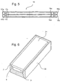
- FIG. 6 shows a container 20 with an attached cover 21 in the unwelded state in a perspective view, wherein for illustrating the impact geometry of the front portion is shown in sectional view.
- a rectangular in cross-section cavity 3 is formed.
- the lid 21 is first connected to the container 20 by a heat conduction weld around the lid 21 and in a second step by a deep weld. Both welds are done with a laser.
- Such welded containers are used for example in switchgear, wherein switching elements and a protective gas (SF 6 ) are provided in the containers.
- SF 6 protective gas
- cavity bodies for example cavity profiles as in FIG. 1 , Distribution rings as in FIG. 5 or container with lid as in FIG. 6 , the different impact geometries in the FIGS. 1, 2a-2d used in combination.
- the hollow body can straight or curved semi-finished products, eg
Landscapes
- Engineering & Computer Science (AREA)
- Mechanical Engineering (AREA)
- Physics & Mathematics (AREA)
- Optics & Photonics (AREA)
- Plasma & Fusion (AREA)
- Laser Beam Processing (AREA)
- Welding Or Cutting Using Electron Beams (AREA)
- Manufacture Of Alloys Or Alloy Compounds (AREA)
- Arc Welding In General (AREA)
Claims (20)
- Procédé de soudage d'au moins deux pièces (2, 4, 20, 21) de préférence métalliques au moyen d'un faisceau d'énergie, de préférence un faisceau laser, le long d'un joint de soudure, ledit joint de soudure comportant une fente (8) ouverte vers le côté orienté vers la tête de soudage et une zone d'appui (6), disposée dans la zone du pied de la fente (8), dans laquelle les pièces sont en appui les unes contre les autres et laquelle termine le joint de soudure sur le côté opposé à la tête de soudage, dans lequel procédé
dans une première étape, les pièces (2, 4, 20, 21) sont assemblées dans la zone d'appui (6) par soudage par conduction de chaleur moyennant la formation d'un cordon de soudure (12), le faisceau d'énergie dans le soudage par conduction de chaleur étant acheminé depuis le côté orienté vers la tête de soudage, et
dans une deuxième étape, les pièces sont assemblées dans la zone de la fente et le long du cordon de soudure (12) par un soudage profond par faisceau d'électrons, le faisceau d'énergie dans le soudage profond étant acheminé depuis le côté orienté vers la tête de soudage, le cordon de soudure (12) empêchant que des émissions du processus, notamment des éclaboussures de métal en fusion, des fumées, s'échappent sur le côté opposé à la tête de soudage pendant le soudage par faisceau laser ou le soudage par faisceau d'électrons. - Procédé selon la revendication 1, caractérisé en ce que pendant le soudage par faisceau laser ou le soudage par faisceau d'électrons, on utilise un matériau d'apport, de préférence de la poudre, en particulier un fil d'apport, et/ou un capillaire de vapeur est formé pendant le soudage par faisceau laser ou le soudage par faisceau d'électrons.
- Procédé selon l'une quelconque des revendications précédentes, caractérisé en ce que, pour le soudage par conduction de chaleur, on utilise une installation laser, une installation à faisceau d'électrons ou une installation de soudage à l'arc TIG ou une installation de soudage par procédé MIG ou une installation de soudage par procédé MAG.
- Procédé selon l'une quelconque des revendications précédentes, caractérisé en ce que le cordon de soudure obtenu par conduction de chaleur fixe les pièces l'une contre l'autre et/ou scelle le joint de soudure sur le côté opposé à la tête de soudage.
- Procédé selon l'une quelconque des revendications précédentes, caractérisé en ce que le cordon soudure par conduction de chaleur est réalisé sur le côté opposé à la tête de soudage avec une surface sans fente et/ou concave.
- Procédé selon l'une quelconque des revendications précédentes, caractérisé en ce que la fente a une section divergeant vers la tête de soudage, de préférence réalisée sensiblement en forme de V, sachant qu'il est prévu de préférence que soit les deux pièces, soit seulement une pièce comportent ou comporte un chanfrein pour la réalisation de la fente.
- Procédé selon la revendication 6, caractérisé en ce que l'angle complet d'ouverture de la fente avec une section sensiblement en forme de V se situe entre 15° et 45°, de préférence entre 20° et 40°, en particulier entre 25° et 35°.
- Procédé selon la revendication 6 ou 7, caractérisé en ce que l'angle caustique ou l'angle complet d'ouverture du faisceau laser incident est inférieur à l'angle complet d'ouverture de la fente sensiblement en forme de V.
- Procédé selon l'une quelconque des revendications 1 à 5, caractérisé en ce que la fente est réalisée avec une section sensiblement rectangulaire.
- Procédé selon l'une quelconque des revendications précédentes, caractérisé en ce que la zone d'appui est plane, sachant qu'il est prévu de préférence que les pièces dans la zone d'appui sont réalisées de manière complémentaire et/ou par conjugaison de forme et/ou de manière étanche et/ou sont en contact plan l'une contre l'autre.
- Procédé selon la revendication 10, caractérisé en ce que la zone d'appui dans la dimension transversale du joint de soudure est inférieure à 2 mm, de préférence inférieure à 1 mm, et supérieure à 0,2 mm.
- Procédé selon l'une quelconque des revendications 1 à 9, caractérisé en ce que la zone d'appui est réalisée en forme de ligne, sachant qu'il est prévu de préférence que la zone d'appui est formée par la zone de contact entre un chanfrein de l'une des pièces et un bord de l'autre pièce en appui sur le chanfrein.
- Procédé selon l'une quelconque des revendications précédentes, caractérisé en ce qu'une cavité est formée par les deux pièces, le côté opposé à la tête de soudage étant orienté vers la cavité.
- Procédé selon l'une quelconque des revendications précédentes, caractérisé en ce que le procédé est utilisé pour la réalisation de bagues de distribution, sachant qu'il est prévu d'utiliser pour l'une des pièces une bague avec une rainure périphérique, de préférence une rainure périphérique en forme de U, et d'utiliser une bande pour la deuxième pièce, les pièces formant conjointement une cavité entourant la bague, en particulier un canal de distribution.
- Corps assemblé par au moins deux pièces, en particulier corps creux, réalisé de préférence selon le procédé selon l'une des revendications 1 à 14, comportant une première pièce, réalisée de préférence sous forme de corps de base (2, 20), et une deuxième pièce, réalisée de préférence sous forme de couvercle (4, 21), les deux pièces étant réalisées de préférence dans un matériau métallique,
la deuxième pièce (4, 21) et la première pièce (2, 20) étant adjacentes, formant de préférence une cavité (3, 17a, b, c, d) et étant assemblées l'une à l'autre par au moins un ensemble de cordons de soudure par laser,
l'ensemble de cordons de soudure par laser s'étendant en continu depuis un premier côté, de préférence le côté extérieur du corps assemblé, de préférence un corps creux, jusqu'à un deuxième côté du corps assemblé, de préférence jusqu'à la cavité (3, 17a, b, c, d) du corps creux,
l'ensemble de cordons de soudure par laser étant formé par un cordon de soudure (12) obtenu par conduction de chaleur et par un cordon de soudure par faisceau laser ou par faisceau d'électrons, réalisé sous forme de cordon de soudure profond (14),
caractérisé en ce que
le cordon de soudure (12) par conduction de chaleur est réalisé sur le deuxième côté, de préférence en étant adjacent à la cavité (3, 17a, b, c, d), et le cordon de soudure profond (14) est délimité vers le deuxième côté, de préférence vers la cavité (3, 17a, b, c, d), par le cordon de soudure (12) par conduction de chaleur. - Corps assemblé selon la revendication 15, caractérisé en ce que le cordon de soudure par faisceau laser ou par faisceau d'électrons, qui est réalisé de préférence sous forme de cordon de soudure profond (14), est formé par un capillaire de vapeur (15) solidifié, qui pénètre dans le cordon de soudure (12) par conduction de chaleur, toutefois ne traverse pas celui-ci de manière débouchante jusque sur le côté du cordon de soudure opposé à la tête de soudage.
- Corps assemblé selon la revendication 15 ou 16 caractérisé en ce que le cordon de soudure par faisceau laser ou par faisceau d'électrons, qui est réalisé de préférence sous forme de cordon de soudure profond (14), a une section qui s'élargit vers le premier côté du corps assemblé, de préférence vers le côté extérieur du corps creux, et/ou en ce que l'ouverture d'introduction du capillaire de vapeur du cordon de soudure profond (14) est disposée sur le premier côté du corps assemblé, de préférence sur le côté extérieur du corps creux.
- Corps assemblé selon l'une quelconque des revendications 15 à 17, caractérisé en ce que l'axe de la dimension en profondeur, de préférence l'axe médian longitudinal, du cordon de soudure par faisceau laser ou par faisceau d'électrons, qui est réalisé de préférence sous forme de cordon de soudure profond, est incliné par rapport à la surface du premier côté, de préférence du côté extérieur du corps assemblé, de préférence du corps creux.
- Corps assemblé selon l'une quelconque des revendications 15 à 18, caractérisé en ce que la partie du cordon de soudure (12) par conduction de chaleur, adjacente au deuxième côté, de préférence à la cavité (3, 17a, b, c, d), comporte une surface (13) concave.
- Corps assemblé selon l'une quelconque des revendications 15 à 19, caractérisé en ce que le corps assemblé est réalisé sous la forme d'une bague de distribution (16) avec au moins une cavité périphérique réalisée dans la bague de distribution, en particulier au moins un canal de distribution (17a, b, c, d), et de préférence il est prévu que le premier corps, de préférence le corps de base, est réalisé sous la forme d'une bague avec au moins une rainure périphérique, en particulier au moins une rainure périphérique, de préférence rectangulaire, et/ou le deuxième corps, de préférence le couvercle, est réalisé sous forme de bande (18a, b, c, d).
Applications Claiming Priority (2)
| Application Number | Priority Date | Filing Date | Title |
|---|---|---|---|
| DE10346072 | 2003-09-26 | ||
| DE10346072A DE10346072A1 (de) | 2003-09-26 | 2003-09-26 | Schweißverfahren, zusammengesetzter Körper und Verwendung einer Laseranlage zur Herstellung des zusammengesetzten Körpers |
Publications (2)
| Publication Number | Publication Date |
|---|---|
| EP1518633A1 EP1518633A1 (fr) | 2005-03-30 |
| EP1518633B1 true EP1518633B1 (fr) | 2008-04-23 |
Family
ID=34178038
Family Applications (1)
| Application Number | Title | Priority Date | Filing Date |
|---|---|---|---|
| EP04022609A Expired - Lifetime EP1518633B1 (fr) | 2003-09-26 | 2004-09-22 | Procédé de soudage et article assemblé |
Country Status (3)
| Country | Link |
|---|---|
| EP (1) | EP1518633B1 (fr) |
| AT (1) | ATE392982T1 (fr) |
| DE (2) | DE10346072A1 (fr) |
Cited By (2)
| Publication number | Priority date | Publication date | Assignee | Title |
|---|---|---|---|---|
| CN102648433A (zh) * | 2009-08-28 | 2012-08-22 | 赖纳·瓦格纳 | 眼镜,具有眼镜元件和铰链部分的装置,和将铰链部分固定在眼镜元件上的方法 |
| US11346618B1 (en) * | 2018-01-22 | 2022-05-31 | Hudson Products Corporation | Boxed header for air-cooled heat exchanger |
Families Citing this family (10)
| Publication number | Priority date | Publication date | Assignee | Title |
|---|---|---|---|---|
| DE102011003469B4 (de) * | 2011-02-01 | 2013-05-29 | Siemens Aktiengesellschaft | Verfahren zur Herstellung eines Gehäuseteils eines Tubinengehäuses für eine Dampfturbine |
| DE102014200033A1 (de) * | 2014-01-07 | 2015-07-09 | Siemens Aktiengesellschaft | Anpassung der Parameter beim Schweißverfahren am Ende einer Schweißnaht |
| DE102014226492A1 (de) | 2014-12-18 | 2016-06-23 | Sitech Sitztechnik Gmbh | Verfahren zum Verbinden von Beschlagteilen für einen Sitzlehnenversteller auf FeMn-Basis |
| DE102015222823B4 (de) * | 2015-11-19 | 2023-12-28 | Brose Fahrzeugteile SE & Co. Kommanditgesellschaft, Coburg | Fügeverfahren, kraftübertragende Winkelanordnung und Längsverstelleinrichtung |
| DE102017202671A1 (de) | 2017-02-20 | 2018-08-23 | Bayerische Motoren Werke Aktiengesellschaft | Verfahren zum Verschweißen zweier Blechbauteile und Bauteilverbund |
| DE102019202317A1 (de) * | 2018-02-23 | 2019-08-29 | Reiner Wagner | Verfahren zum Fügen zweier Bauteile miteinander durch Laserschweißen und Bauteil-Anordnung |
| DE102018209143A1 (de) * | 2018-06-08 | 2019-12-12 | Robert Bosch Gmbh | Verfahren zur Herstellung einer stoffschlüssigen Laserbondverbindung sowie Vorrichtung zur Ausbildung einer Laserbondverbindung |
| DE102018120389A1 (de) * | 2018-08-21 | 2020-02-27 | Kirchhoff Automotive Deutschland Gmbh | Baugruppe sowie Batteriegehäuse mit mehreren dieser Baugruppen |
| CN114713959B (zh) * | 2022-04-19 | 2024-07-23 | 中国航发动力股份有限公司 | 一种航空发动机筒体组件双面成形焊接接头及其成型方法 |
| DE102022004663A1 (de) | 2022-12-12 | 2023-03-09 | Mercedes-Benz Group AG | Verfahren zur Herstellung eines Bauteils |
Family Cites Families (3)
| Publication number | Priority date | Publication date | Assignee | Title |
|---|---|---|---|---|
| JPS50159442A (fr) * | 1974-06-14 | 1975-12-24 | ||
| US5796069A (en) * | 1997-01-10 | 1998-08-18 | Crc-Evans Pipeline International, Inc. | Arc and laser welding process for pipeline |
| JP3928336B2 (ja) * | 1999-09-21 | 2007-06-13 | 株式会社豊田自動織機 | 圧縮機用ピストンの製造方法 |
-
2003
- 2003-09-26 DE DE10346072A patent/DE10346072A1/de not_active Withdrawn
-
2004
- 2004-09-22 DE DE502004006892T patent/DE502004006892D1/de not_active Expired - Lifetime
- 2004-09-22 EP EP04022609A patent/EP1518633B1/fr not_active Expired - Lifetime
- 2004-09-22 AT AT04022609T patent/ATE392982T1/de active
Cited By (2)
| Publication number | Priority date | Publication date | Assignee | Title |
|---|---|---|---|---|
| CN102648433A (zh) * | 2009-08-28 | 2012-08-22 | 赖纳·瓦格纳 | 眼镜,具有眼镜元件和铰链部分的装置,和将铰链部分固定在眼镜元件上的方法 |
| US11346618B1 (en) * | 2018-01-22 | 2022-05-31 | Hudson Products Corporation | Boxed header for air-cooled heat exchanger |
Also Published As
| Publication number | Publication date |
|---|---|
| EP1518633A1 (fr) | 2005-03-30 |
| ATE392982T1 (de) | 2008-05-15 |
| DE10346072A1 (de) | 2005-04-21 |
| DE502004006892D1 (de) | 2008-06-05 |
Similar Documents
| Publication | Publication Date | Title |
|---|---|---|
| EP3600746B1 (fr) | Procédé servant à fabriquer un composant pour une application de véhicule | |
| EP1518633B1 (fr) | Procédé de soudage et article assemblé | |
| EP1440761A1 (fr) | Procédé d'ébavurage de tôles formées par emboutissage | |
| EP0665079A1 (fr) | Procédé pour reliér pièces métalliques au moyen d'un soudage par fusion à l'arc | |
| EP3073134B1 (fr) | Procédé de fabrication d'un ensemble chassis et ensemble chassis fabrique selon un tel procédé | |
| EP2384255B1 (fr) | Procédé dôbtention d'un joint de soudure à recouvrement et joint obtenu | |
| EP1941964B1 (fr) | Procédé de soudage par compression et résistance | |
| DE2428828B2 (de) | Verfahren zum Elektronenstrahlverschweißen zweier Metallwerkstücke | |
| DE102004045961A1 (de) | System und Verfahren zur Herstellung von geschweissten Strukturen, sowie ein Schweisszusatzwerkstoff hierfür | |
| DE19930931A1 (de) | Schichtverbund mit geschweißter Metalleinlage | |
| DE19623103A1 (de) | Verfahren zur Herstellung einer T-Verbindung durch Schweißen sowie Profil und Schweißplättchen zur Durchführung des Verfahrens | |
| DE10315976A1 (de) | Verfahren zum Vorbereiten des Fügebereichs eines beschichteten Werkstücks | |
| DE3926781A1 (de) | Verfahren zum verschweissen mit laserstrahlung und vorrichtung zur durchfuehrung des verfahrens | |
| DE19625873A1 (de) | Verfahren zur Verbindung von Fügepartner | |
| DE10306697A1 (de) | Verfahren zum Schweißverbinden von Kunststoffteilen mit Hilfe von Laserstrahlung | |
| DE10342921B4 (de) | Verfahren zum Verschweißen von Kunststoffen und einem hierzu notwendigen Schweißmittel | |
| DE3437823A1 (de) | Schweissverbindung | |
| DE19950437C2 (de) | Schweißverbindung sowie Verfahren zum Schweißen von Werkstücken | |
| DE2122059B2 (de) | Elektronenstrahlschweiß verfahren | |
| DE19947314A1 (de) | Vorrichtung umfassend eine Schweißverbindung | |
| DE102004008108A1 (de) | Überlappstoß zum Schweißen von beschichteten Werkstücken | |
| DE19834775A1 (de) | Verfahren zum Zusammenschweißen von zwei Werkstück-Randbereichen | |
| DE2537115A1 (de) | Verfahren zum elektronenstrahlschweissen | |
| DE102024206221B3 (de) | Anordnung von mittels eines Strahlschweißverfahrens miteinander verbundenen Bauteilen und entsprechendes Herstellungsverfahren | |
| AT410416B (de) | Vorrichtung und verfahren zum plasma-schweissen von türen und klappen |
Legal Events
| Date | Code | Title | Description |
|---|---|---|---|
| PUAI | Public reference made under article 153(3) epc to a published international application that has entered the european phase |
Free format text: ORIGINAL CODE: 0009012 |
|
| AK | Designated contracting states |
Kind code of ref document: A1 Designated state(s): AT BE BG CH CY CZ DE DK EE ES FI FR GB GR HU IE IT LI LU MC NL PL PT RO SE SI SK TR |
|
| AX | Request for extension of the european patent |
Extension state: AL HR LT LV MK |
|
| 17P | Request for examination filed |
Effective date: 20050730 |
|
| AKX | Designation fees paid |
Designated state(s): AT BE BG CH CY CZ DE DK EE ES FI FR GB GR HU IE IT LI LU MC NL PL PT RO SE SI SK TR |
|
| GRAP | Despatch of communication of intention to grant a patent |
Free format text: ORIGINAL CODE: EPIDOSNIGR1 |
|
| RTI1 | Title (correction) |
Free format text: WELDING PROCESS AND ASSEMBLED BODIES |
|
| GRAS | Grant fee paid |
Free format text: ORIGINAL CODE: EPIDOSNIGR3 |
|
| GRAA | (expected) grant |
Free format text: ORIGINAL CODE: 0009210 |
|
| AK | Designated contracting states |
Kind code of ref document: B1 Designated state(s): AT BE BG CH CY CZ DE DK EE ES FI FR GB GR HU IE IT LI LU MC NL PL PT RO SE SI SK TR |
|
| REG | Reference to a national code |
Ref country code: GB Ref legal event code: FG4D Free format text: NOT ENGLISH |
|
| REG | Reference to a national code |
Ref country code: CH Ref legal event code: EP |
|
| REF | Corresponds to: |
Ref document number: 502004006892 Country of ref document: DE Date of ref document: 20080605 Kind code of ref document: P |
|
| REG | Reference to a national code |
Ref country code: IE Ref legal event code: FG4D Free format text: LANGUAGE OF EP DOCUMENT: GERMAN |
|
| REG | Reference to a national code |
Ref country code: SE Ref legal event code: TRGR |
|
| REG | Reference to a national code |
Ref country code: CH Ref legal event code: NV Representative=s name: FIAMMENGHI-FIAMMENGHI |
|
| PG25 | Lapsed in a contracting state [announced via postgrant information from national office to epo] |
Ref country code: SI Free format text: LAPSE BECAUSE OF FAILURE TO SUBMIT A TRANSLATION OF THE DESCRIPTION OR TO PAY THE FEE WITHIN THE PRESCRIBED TIME-LIMIT Effective date: 20080423 |
|
| NLV1 | Nl: lapsed or annulled due to failure to fulfill the requirements of art. 29p and 29m of the patents act | ||
| PG25 | Lapsed in a contracting state [announced via postgrant information from national office to epo] |
Ref country code: FI Free format text: LAPSE BECAUSE OF FAILURE TO SUBMIT A TRANSLATION OF THE DESCRIPTION OR TO PAY THE FEE WITHIN THE PRESCRIBED TIME-LIMIT Effective date: 20080423 Ref country code: PT Free format text: LAPSE BECAUSE OF FAILURE TO SUBMIT A TRANSLATION OF THE DESCRIPTION OR TO PAY THE FEE WITHIN THE PRESCRIBED TIME-LIMIT Effective date: 20080923 Ref country code: NL Free format text: LAPSE BECAUSE OF FAILURE TO SUBMIT A TRANSLATION OF THE DESCRIPTION OR TO PAY THE FEE WITHIN THE PRESCRIBED TIME-LIMIT Effective date: 20080423 Ref country code: BG Free format text: LAPSE BECAUSE OF FAILURE TO SUBMIT A TRANSLATION OF THE DESCRIPTION OR TO PAY THE FEE WITHIN THE PRESCRIBED TIME-LIMIT Effective date: 20080723 Ref country code: ES Free format text: LAPSE BECAUSE OF FAILURE TO SUBMIT A TRANSLATION OF THE DESCRIPTION OR TO PAY THE FEE WITHIN THE PRESCRIBED TIME-LIMIT Effective date: 20080803 |
|
| PG25 | Lapsed in a contracting state [announced via postgrant information from national office to epo] |
Ref country code: PL Free format text: LAPSE BECAUSE OF FAILURE TO SUBMIT A TRANSLATION OF THE DESCRIPTION OR TO PAY THE FEE WITHIN THE PRESCRIBED TIME-LIMIT Effective date: 20080423 |
|
| REG | Reference to a national code |
Ref country code: IE Ref legal event code: FD4D |
|
| PG25 | Lapsed in a contracting state [announced via postgrant information from national office to epo] |
Ref country code: IE Free format text: LAPSE BECAUSE OF FAILURE TO SUBMIT A TRANSLATION OF THE DESCRIPTION OR TO PAY THE FEE WITHIN THE PRESCRIBED TIME-LIMIT Effective date: 20080423 Ref country code: DK Free format text: LAPSE BECAUSE OF FAILURE TO SUBMIT A TRANSLATION OF THE DESCRIPTION OR TO PAY THE FEE WITHIN THE PRESCRIBED TIME-LIMIT Effective date: 20080423 |
|
| ET | Fr: translation filed | ||
| PG25 | Lapsed in a contracting state [announced via postgrant information from national office to epo] |
Ref country code: RO Free format text: LAPSE BECAUSE OF FAILURE TO SUBMIT A TRANSLATION OF THE DESCRIPTION OR TO PAY THE FEE WITHIN THE PRESCRIBED TIME-LIMIT Effective date: 20080423 |
|
| PLBE | No opposition filed within time limit |
Free format text: ORIGINAL CODE: 0009261 |
|
| STAA | Information on the status of an ep patent application or granted ep patent |
Free format text: STATUS: NO OPPOSITION FILED WITHIN TIME LIMIT |
|
| BERE | Be: lapsed |
Owner name: ERLAS ERLANGER LASERTECHNIK G.M.B.H. Effective date: 20080930 |
|
| 26N | No opposition filed |
Effective date: 20090126 |
|
| PG25 | Lapsed in a contracting state [announced via postgrant information from national office to epo] |
Ref country code: EE Free format text: LAPSE BECAUSE OF FAILURE TO SUBMIT A TRANSLATION OF THE DESCRIPTION OR TO PAY THE FEE WITHIN THE PRESCRIBED TIME-LIMIT Effective date: 20080423 Ref country code: MC Free format text: LAPSE BECAUSE OF NON-PAYMENT OF DUE FEES Effective date: 20080930 |
|
| PG25 | Lapsed in a contracting state [announced via postgrant information from national office to epo] |
Ref country code: BE Free format text: LAPSE BECAUSE OF NON-PAYMENT OF DUE FEES Effective date: 20080930 |
|
| PG25 | Lapsed in a contracting state [announced via postgrant information from national office to epo] |
Ref country code: CY Free format text: LAPSE BECAUSE OF FAILURE TO SUBMIT A TRANSLATION OF THE DESCRIPTION OR TO PAY THE FEE WITHIN THE PRESCRIBED TIME-LIMIT Effective date: 20080423 Ref country code: LU Free format text: LAPSE BECAUSE OF NON-PAYMENT OF DUE FEES Effective date: 20080922 Ref country code: HU Free format text: LAPSE BECAUSE OF FAILURE TO SUBMIT A TRANSLATION OF THE DESCRIPTION OR TO PAY THE FEE WITHIN THE PRESCRIBED TIME-LIMIT Effective date: 20081024 |
|
| PG25 | Lapsed in a contracting state [announced via postgrant information from national office to epo] |
Ref country code: TR Free format text: LAPSE BECAUSE OF FAILURE TO SUBMIT A TRANSLATION OF THE DESCRIPTION OR TO PAY THE FEE WITHIN THE PRESCRIBED TIME-LIMIT Effective date: 20080423 |
|
| PG25 | Lapsed in a contracting state [announced via postgrant information from national office to epo] |
Ref country code: GR Free format text: LAPSE BECAUSE OF FAILURE TO SUBMIT A TRANSLATION OF THE DESCRIPTION OR TO PAY THE FEE WITHIN THE PRESCRIBED TIME-LIMIT Effective date: 20080724 |
|
| REG | Reference to a national code |
Ref country code: FR Ref legal event code: PLFP Year of fee payment: 13 |
|
| REG | Reference to a national code |
Ref country code: FR Ref legal event code: PLFP Year of fee payment: 14 |
|
| PGFP | Annual fee paid to national office [announced via postgrant information from national office to epo] |
Ref country code: CH Payment date: 20170925 Year of fee payment: 14 Ref country code: SK Payment date: 20170919 Year of fee payment: 14 Ref country code: GB Payment date: 20170925 Year of fee payment: 14 |
|
| PGFP | Annual fee paid to national office [announced via postgrant information from national office to epo] |
Ref country code: AT Payment date: 20170920 Year of fee payment: 14 Ref country code: SE Payment date: 20170925 Year of fee payment: 14 |
|
| REG | Reference to a national code |
Ref country code: FR Ref legal event code: PLFP Year of fee payment: 15 |
|
| PG25 | Lapsed in a contracting state [announced via postgrant information from national office to epo] |
Ref country code: CZ Free format text: LAPSE BECAUSE OF NON-PAYMENT OF DUE FEES Effective date: 20180922 |
|
| REG | Reference to a national code |
Ref country code: SE Ref legal event code: EUG Ref country code: CH Ref legal event code: PL |
|
| REG | Reference to a national code |
Ref country code: AT Ref legal event code: MM01 Ref document number: 392982 Country of ref document: AT Kind code of ref document: T Effective date: 20180922 |
|
| GBPC | Gb: european patent ceased through non-payment of renewal fee |
Effective date: 20180922 |
|
| PG25 | Lapsed in a contracting state [announced via postgrant information from national office to epo] |
Ref country code: SE Free format text: LAPSE BECAUSE OF NON-PAYMENT OF DUE FEES Effective date: 20180923 |
|
| REG | Reference to a national code |
Ref country code: SK Ref legal event code: MM4A Ref document number: E 4074 Country of ref document: SK Effective date: 20180922 |
|
| PG25 | Lapsed in a contracting state [announced via postgrant information from national office to epo] |
Ref country code: CH Free format text: LAPSE BECAUSE OF NON-PAYMENT OF DUE FEES Effective date: 20180930 Ref country code: LI Free format text: LAPSE BECAUSE OF NON-PAYMENT OF DUE FEES Effective date: 20180930 Ref country code: SK Free format text: LAPSE BECAUSE OF NON-PAYMENT OF DUE FEES Effective date: 20180922 |
|
| PG25 | Lapsed in a contracting state [announced via postgrant information from national office to epo] |
Ref country code: AT Free format text: LAPSE BECAUSE OF NON-PAYMENT OF DUE FEES Effective date: 20180922 Ref country code: GB Free format text: LAPSE BECAUSE OF NON-PAYMENT OF DUE FEES Effective date: 20180922 |
|
| PGFP | Annual fee paid to national office [announced via postgrant information from national office to epo] |
Ref country code: FR Payment date: 20230929 Year of fee payment: 20 Ref country code: DE Payment date: 20230920 Year of fee payment: 20 |
|
| PGFP | Annual fee paid to national office [announced via postgrant information from national office to epo] |
Ref country code: IT Payment date: 20230922 Year of fee payment: 20 |
|
| REG | Reference to a national code |
Ref country code: DE Ref legal event code: R071 Ref document number: 502004006892 Country of ref document: DE |