EP1518633B1 - Welding process and assembled bodies - Google Patents
Welding process and assembled bodies Download PDFInfo
- Publication number
- EP1518633B1 EP1518633B1 EP04022609A EP04022609A EP1518633B1 EP 1518633 B1 EP1518633 B1 EP 1518633B1 EP 04022609 A EP04022609 A EP 04022609A EP 04022609 A EP04022609 A EP 04022609A EP 1518633 B1 EP1518633 B1 EP 1518633B1
- Authority
- EP
- European Patent Office
- Prior art keywords
- weld
- welding
- laser
- heat conduction
- cavity
- Prior art date
- Legal status (The legal status is an assumption and is not a legal conclusion. Google has not performed a legal analysis and makes no representation as to the accuracy of the status listed.)
- Active
Links
- 238000003466 welding Methods 0.000 title claims abstract description 96
- 238000000034 method Methods 0.000 title claims abstract description 54
- 238000010894 electron beam technology Methods 0.000 claims abstract description 14
- 239000000779 smoke Substances 0.000 claims abstract description 8
- 239000000463 material Substances 0.000 claims description 9
- 239000000945 filler Substances 0.000 claims description 6
- 230000035515 penetration Effects 0.000 claims description 5
- 230000000284 resting effect Effects 0.000 claims description 5
- 230000000295 complement effect Effects 0.000 claims description 2
- 239000000843 powder Substances 0.000 claims description 2
- 230000002093 peripheral effect Effects 0.000 claims 4
- 239000007787 solid Substances 0.000 claims 3
- 239000003518 caustics Substances 0.000 claims 1
- 239000003517 fume Substances 0.000 claims 1
- 239000007769 metal material Substances 0.000 claims 1
- 238000007789 sealing Methods 0.000 claims 1
- 230000008021 deposition Effects 0.000 abstract description 3
- 230000015572 biosynthetic process Effects 0.000 abstract description 2
- 239000011796 hollow space material Substances 0.000 abstract 1
- 210000002414 leg Anatomy 0.000 description 29
- 238000009826 distribution Methods 0.000 description 22
- 238000012545 processing Methods 0.000 description 6
- 230000001154 acute effect Effects 0.000 description 5
- 238000003754 machining Methods 0.000 description 5
- 238000004519 manufacturing process Methods 0.000 description 5
- 239000002131 composite material Substances 0.000 description 4
- 230000000694 effects Effects 0.000 description 4
- 239000002245 particle Substances 0.000 description 4
- 238000013461 design Methods 0.000 description 3
- 238000011161 development Methods 0.000 description 3
- 230000018109 developmental process Effects 0.000 description 3
- 238000005516 engineering process Methods 0.000 description 3
- 238000004140 cleaning Methods 0.000 description 2
- 239000007789 gas Substances 0.000 description 2
- 239000007788 liquid Substances 0.000 description 2
- 229910000831 Steel Inorganic materials 0.000 description 1
- 238000010521 absorption reaction Methods 0.000 description 1
- 239000011324 bead Substances 0.000 description 1
- 238000010276 construction Methods 0.000 description 1
- 238000011109 contamination Methods 0.000 description 1
- 238000005520 cutting process Methods 0.000 description 1
- 208000018459 dissociative disease Diseases 0.000 description 1
- 230000017525 heat dissipation Effects 0.000 description 1
- 238000010438 heat treatment Methods 0.000 description 1
- 230000000670 limiting effect Effects 0.000 description 1
- 239000000155 melt Substances 0.000 description 1
- 230000008018 melting Effects 0.000 description 1
- 238000002844 melting Methods 0.000 description 1
- 239000002184 metal Substances 0.000 description 1
- 239000000203 mixture Substances 0.000 description 1
- 230000003287 optical effect Effects 0.000 description 1
- 230000001681 protective effect Effects 0.000 description 1
- 230000005855 radiation Effects 0.000 description 1
- 230000002829 reductive effect Effects 0.000 description 1
- 239000011265 semifinished product Substances 0.000 description 1
- 238000007711 solidification Methods 0.000 description 1
- 230000008023 solidification Effects 0.000 description 1
- 125000006850 spacer group Chemical group 0.000 description 1
- 230000003068 static effect Effects 0.000 description 1
- 239000010959 steel Substances 0.000 description 1
- 238000012549 training Methods 0.000 description 1
- 210000000689 upper leg Anatomy 0.000 description 1
Images

Classifications
-
- B—PERFORMING OPERATIONS; TRANSPORTING
- B23—MACHINE TOOLS; METAL-WORKING NOT OTHERWISE PROVIDED FOR
- B23K—SOLDERING OR UNSOLDERING; WELDING; CLADDING OR PLATING BY SOLDERING OR WELDING; CUTTING BY APPLYING HEAT LOCALLY, e.g. FLAME CUTTING; WORKING BY LASER BEAM
- B23K15/00—Electron-beam welding or cutting
- B23K15/0033—Preliminary treatment
-
- B—PERFORMING OPERATIONS; TRANSPORTING
- B23—MACHINE TOOLS; METAL-WORKING NOT OTHERWISE PROVIDED FOR
- B23K—SOLDERING OR UNSOLDERING; WELDING; CLADDING OR PLATING BY SOLDERING OR WELDING; CUTTING BY APPLYING HEAT LOCALLY, e.g. FLAME CUTTING; WORKING BY LASER BEAM
- B23K15/00—Electron-beam welding or cutting
- B23K15/0046—Welding
- B23K15/0053—Seam welding
- B23K15/0073—Seam welding with interposition of particular material to facilitate connecting the parts, e.g. using a filler
-
- B—PERFORMING OPERATIONS; TRANSPORTING
- B23—MACHINE TOOLS; METAL-WORKING NOT OTHERWISE PROVIDED FOR
- B23K—SOLDERING OR UNSOLDERING; WELDING; CLADDING OR PLATING BY SOLDERING OR WELDING; CUTTING BY APPLYING HEAT LOCALLY, e.g. FLAME CUTTING; WORKING BY LASER BEAM
- B23K26/00—Working by laser beam, e.g. welding, cutting or boring
- B23K26/20—Bonding
- B23K26/21—Bonding by welding
- B23K26/24—Seam welding
-
- B—PERFORMING OPERATIONS; TRANSPORTING
- B23—MACHINE TOOLS; METAL-WORKING NOT OTHERWISE PROVIDED FOR
- B23K—SOLDERING OR UNSOLDERING; WELDING; CLADDING OR PLATING BY SOLDERING OR WELDING; CUTTING BY APPLYING HEAT LOCALLY, e.g. FLAME CUTTING; WORKING BY LASER BEAM
- B23K26/00—Working by laser beam, e.g. welding, cutting or boring
- B23K26/60—Preliminary treatment
-
- B—PERFORMING OPERATIONS; TRANSPORTING
- B23—MACHINE TOOLS; METAL-WORKING NOT OTHERWISE PROVIDED FOR
- B23K—SOLDERING OR UNSOLDERING; WELDING; CLADDING OR PLATING BY SOLDERING OR WELDING; CUTTING BY APPLYING HEAT LOCALLY, e.g. FLAME CUTTING; WORKING BY LASER BEAM
- B23K33/00—Specially-profiled edge portions of workpieces for making soldering or welding connections; Filling the seams formed thereby
- B23K33/004—Filling of continuous seams
Definitions
- the invention relates to a method for welding at least two preferably metallic components by means of an energy beam, preferably a laser beam, along a weld joint, and a body composed of at least two components, preferably a hollow body, which is preferably produced by the above-mentioned method, and the use of a laser system for producing such a composite body.
- a distribution ring for dispensing liquids in bottles.
- a distribution ring has a diameter of up to 6 m and has a circumferential distribution channel, which is formed as a hollow channel with a plurality of openings. The openings are connected to supply and discharge lines or with valves. When filling bottles, the liquid is introduced into the distribution channel and passed through the valves in the bottles.
- the distribution channel is formed by a radially encircling, rectangular in cross-section groove in the Verteilerringoasa and welded onto the Verteilerring Sciences as a cover for the groove band.
- the welding of cover strip with the distributor ring body is carried out in the known methods via a multi-layer TIG welding at a welding speed of about 100 mm / min.
- the multi-layered weld is required to the connection cross-section between the band and the actual distribution ring load-carrying, as occur during operation in the distribution channels large pressures.
- This known manufacturing method for distributor rings has as significant drawbacks that the processing time for welding the bands on the distributor ring body is very long and that the distributor ring warps by the heating during the long welding operation.
- the weld joint has not been completely melted, in particular in the region of the cavity of the distributor channel, so that gaps left in the foot region of the weld joint between the lid and the ring remain open to the cavity. These gaps prevent effective cleaning of the distribution channel, as dirt particles can accumulate in the gaps. Furthermore, under load, the notch effect occurring through the gaps can lead to a failure of the laser weld seam.
- a further problem has been recognized that the cavity is heavily contaminated by the spatter caused by the laser beam deep welding and to the cavity - ie to the distribution channel - open steam capillary, as spilled by the Dampfkapillare spatter, smoke and smoke.
- housings for electrical switchgear are constructed in plate construction. In the manufacture of the housing laser welding is used today for connecting the plates. To prevent that in the Housing internal welding emissions occur, the weld at an acute angle to the joint, often preferably 5 °, introduced. The penetration of emissions into the housing interior can not be reliably prevented in this way.
- the weld joint opens a joint open to the side facing the welding head and one in the region of Has foot of the joint arranged abutment area in which the components abut each other and which closes the weld joint on the side facing away from the welding head, wherein in a first process step, the binding partners are connected in the investment area by thermal conduction welding to form a heat conduction weld and in a second process step the binding partners in Area of the joint and along the heat conduction weld by laser beam or electron beam welding, preferably laser beam or electron beam deep welding, are connected, wherein the heat conduction weld ve prevents process emissions, in particular spatter, smoke or smoke from escaping at the inside of the workpiece during laser beam or electron beam welding.
- the workpieces to be joined are preferably made of metal, but may also consist of plastic or other materials.
- a laser system for generating the energy beam, preferably a laser system, in particular a Nd: YAG, diode or CO 2 laser system, is used, but in modified embodiments of the method, electron beam welding systems can also be used to generate the energy beam.
- the workpieces i. the components to be joined are arranged abutting one another, wherein between the workpieces to be welded joint - the weld joint - is formed.
- the weld joint is welded in the later process steps in the longitudinal direction, ie along the longitudinal extent.
- the weld joint comprises a joint open to the side facing the welding head and a contact region connected to the lower end, ie opposite the opening of the joint, in which the two components to be welded abut each other, ie are in contact with each other. This contact area ends at the workpiece inside.
- the energy beam of the contact region which preferably enters through a gap which is opened through the side facing the welding head is preferably completely welded, so that a heat conduction weld is formed at the location of the contact region.
- the same section of the weld joint is again passed over by an energy beam as in the case of heat conduction welding, wherein the components in the region of the joint are preferably connected by heat conduction or deep welding.
- the heat conduction weld produced during the first process step prevents the vapor capillary formed in the second process step in the case of deep welding from opening to the inside of the work piece and prevents process emissions, in particular spatter, smoke or smoke from escaping from the inside of the work piece.
- the resulting during deep welding vapor capillary is in the direction of the side facing away from the welding head, ie. preferably the workpiece inside limited by the heat conduction weld.
- the method is advantageously carried out when the energy beam is supplied from the workpiece outside. This is the case, for example, when the energy beam enters through the gap open to the workpiece exterior.
- the material mis-volume of the weld joint in the region of the joint can be filled either by melting the material of the material in contact with the excess material or by additional material, preferably powder, filler wire, etc.
- the filler material can be either automatically fed during welding or inserted as a filler before the second step in the joint.
- the method is advantageously formed when the heat conduction welding process is performed so that the weld joint on the side facing away from the welding head by the heat conduction weld, i. preferably the workpiece inside is sealed. This is the case in particular if a uniform, smooth welding bead is produced on the underside of the workpiece by the heat conduction welding.
- the seal prevents dirt particles from escaping from the weld joint to the inside of the workpiece.
- the heat conduction welding process when the heat conduction welding process is performed so that at the side facing away from the welding head side, preferably the workpiece inside a gap-free and / or concave surface is formed.
- a gap-free and / or concave surface is formed.
- Such a design of the surface reduces the notch effect and prevents the deposition of dirt particles on the side facing away from the welding head side of the workpiece, ie preferably the workpiece inside.
- the formation of the heat conduction weld on the relevant workpiece side, ie preferably workpiece underside can by the use of suitable Formiergasen -. As He, Ar, H 2 , N 2 or mixtures of these gases - be supported.
- This training can be achieved by a bevel, rounding or grading of one or both workpieces or a chamfer at one or both workpieces in the region of the weld joint.
- the V-shaped joint may have an opening angle between 15 and 45 °, preferably between 20 and 40 ° and in particular between 25 and 35 °, wherein the information is based on a full angle.
- the full opening angle should be greater than the Kaustikwinkel of the incident laser beam, so that the laser beam can penetrate without too much absorption at the joint walls into the investment area.
- the joint may be formed substantially rectangular in cross section, wherein preferably the diameter of the laser beam in the initial region of the joint is smaller the width of the joint is formed.
- the abutment region that is to say the contact region between the workpieces, is of planar design.
- This flat contact area is dimensioned in its dimensions so that it is completely melted during heat conduction welding.
- it is provided to design the impact geometry such that the masses of the workpieces adjacent to the abutment region are distributed in such a way that the heat dissipation from the abutment region into the workpieces is approximately the same for both workpieces.
- the method is used to join two workpieces forming a cavity with the workpiece inside facing the cavity.
- the cavity may be a completely closed or a multi-apertured and / or apertured cavity.
- the method also finds application for the connection of workpieces, wherein the welding impact from one side, in particular the workpiece inner side, is difficult or impossible for the energy beam.
- the method for the production of a distribution ring of the type described above can be used, which consists of a distributor ring body with circumferential groove and a band, wherein the tape is welded to close the groove on the distributor ring body.
- the distribution ring may also have multiple distribution channels.
- the object underlying the invention is further achieved with the composite of several components body according to claim 15.
- it may be a cavity body consisting of a body and a lid which together form a cavity and interconnected with at least one laser weld assembly, the laser weld assembly extending continuously from the outside of the cavity body to the cavity, the laser weld assembly preferably from a heat conduction weld and a deep weld, and wherein it is provided that the heat conduction weld is formed adjacent to the cavity and the deep weld is limited by the heat conduction weld to the cavity.
- the laser weld seam arrangement is designed as a juxtaposition of a first and a second weld seam, preferably a heat conduction weld seam and a deep weld seam, wherein the laser weld seam assembly begins with the deep weld seam in the case of the hollow body on the outside of the hollow body.
- the heat pipe weld Directly connected to the deep weld is the heat pipe weld, which immediately adjoins the cavity of the cavity body with its end portion.
- the deep welding effect and thus the production of the deep weld is achieved by forming a vapor capillary.
- the penetration depth is greater than or equal to the penetration depth of the vapor capillaries.
- the laser radiation is absorbed on the walls of the vapor capillary. The result is a steam bath surrounding the melt bath, which forms the deep weld after solidification.
- the deep weld penetrates the heat weld, but does not penetrate it completely.
- the concave surface very effectively prevents deposition of dirt particles and facilitates cleaning of the cavity. Furthermore, the concave surface reduces the notch effect at the joint by attacking forces.
- the cavity body is a distribution ring of the type described above.
- the laser system preferably has a guiding machine, in particular a Cartesian guiding machine or a robot, relative to the welding head to move the workpiece precisely guided.
- a guiding machine in particular a Cartesian guiding machine or a robot
- the welding head or alone the workpiece or both can be moved.
- the tensioning means may be static tensioning means, e.g. Clamping jaws, or dynamic clamping means, e.g. Pressure rollers or Antikfinger, which are moved with the energy beam act.
- the laser system has a laser aggregate, which is preferably formed from a CO 2 or Nd: YAG laser or a diode laser or a CO 2 laser with an output power of more than 1,000 watts.
- this has a shock-tracking sensor, which senses the position of the weld joint.
- the sensor can be designed as an optical - in particular as a light section sensor - or as a tactile sensor.
- the measured sensor values are either on-line, i. during ongoing processing, or off-line, i. Before machining, they are offset against a programmed machining path or form the basis for creating a machining path.
- FIG. 1 shows a U-profile 2, which is closed in longitudinal extension by an applied cover band 4, so that a cavity body 1 is formed with a rectangular cavity 3.
- the hollow body 1 is in FIG. 1 shown in the unwelded state.
- the U-profile 2 consists of a rectangular base body, to which two mutually parallel and mutually mirror-symmetrical legs 5 are arranged, wherein the base body and legs 5 in the illustration in FIG. 1 to form a standing U.
- Modified U-profile body with asymmetrical legs for example with different lengths and / or unparallel legs are conceivable.
- the U-profile may be formed as a one-piece, preferably extruded or exciting manufactured one-piece body or as a multi-part composite body.
- the two legs 5 have at their directed to the cavity 3 inner sides in each case a step with a horizontal, parallel to the bottom of the cavity 3 aligned support shoulder 6.
- the support heels 6 are arranged on the legs 5 opposite at the same height.
- the adjoining the support heels 6 leg end portions are each bevelled on the inside to form a chamfer 7.
- the chamfers 7 are aligned divergently from each other. Between the chamfer 7 and the support shoulder 6 an obtuse angle alpha of about 120 ° is formed in each case.
- the chamfer 7 joins each directly to the support shoulder 6 to form an edge 22 and extends to the distal end of the leg. 5
- the cover strip 4 is rectangular in cross section and is lying on the receiving heels 6 of the U-profile 2, wherein the inner sides of the U-shaped profile 2 and the underside of the cover strip 4 form the rectangular cross-section cavity 3.
- the edge regions of the underside-that is, the side facing the cavity 3 -the cover strip 4 and the support heels 6 of the U-profile 2 are in surface contact with one another.
- the cover band 4 rests on both sides supported on the support heels 6, wherein the left lower edge of the cover strip 4 close to the edge 22 of the left support portion 6 and the right lower edge of the cover strip 4 is close to the edge 22 of the right support paragraph 6.
- the tolerance for the width of the cover strip is determined by the width of the support paragraph. The width may not exceed the distance between the edges 22 to each other.
- the minimum dimension of the lid width is calculated from the width of the cavity plus the width of the support paragraph 6 plus about 0.2 mm.
- a V-shaped joint 8 between the narrow sides of the cover strip 4 and the chamfers 7 is formed with inserted cover strip 4 respectively.
- This gap 8 is to the outside of the cavity body 1 in FIG. 1 formed to be larger at the top and has an acute opening angle gamma of about 30 ° in cross-section.
- the V-shaped joint is closed by laser deep welding in a second processing step. In both processing steps, the laser beam is radiated from the cavity body outside in the joint 8.
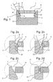
- FIGS. 2a-2d be alternative embodiments for the impact geometry in FIG. 1 explained.
- the detail is shown, the detail A in FIG. 1 corresponds, and essentially represents the weld.
- FIG. 2a shows a first modified embodiment of the detail A in FIG. 1 , It is a leg 5 and a resting on a support shoulder 6 of the leg 5 cover band 4 is shown, wherein between legs 5 and cover band 6, a gap 8 is formed.
- the gap 8 is similar to the fugue in FIG. 1 V-shaped, but deviating from it is formed as follows:
- the leg 5 only has a rectangular recess.
- the chamfer 7 on the leg 5 in FIG. 1 is on the thigh 5 in FIG. 2a unavailable.
- the rectangular recess comprises a support shoulder 6, which analogous to the execution in FIG. 1 is aligned parallel to the bottom of the cavity 3, and a directly connected to the support shoulder 6 vertical section.
- the cover band 4 in FIG. 2a is contrary to the execution in FIG. 1 in the longitudinal direction in each case laterally beveled by a chamfer 7 ', so that an acute angle beta of approximately 60 ° is formed in the cross section between the underside and the narrow side of the cover strip 4.
- the joint 8 is formed with the cover strip 4 lying on the support shoulders 6 between the vertical section of the rectangular recess of the leg 5 and the bevelled side of the cover strip 4.
- the joint has an acute opening angle gamma of about 30 °.
- FIG. 2b shows a second modified embodiment of the detail A in FIG. 1 , wherein the leg 5 as in the embodiment in FIG. 1 is formed with a support shoulder 6 and with a chamfer 7 with an angle alpha.
- the cover strip 4 has as in the embodiment in FIG. 2a a chamfer 7 'with an angle beta.
- the angle alpha is approximately 100 ° and the angle beta is approximately 80 °.
- the joint 8 is formed when resting on the support heels 6 cover band 4 between the chamfer 7 of the leg 5 and the chamfer 7 'of the cover band 4.
- the joint has an acute opening angle gamma of about 20 °.
- Figure 2c shows a third alternative embodiment of the detail A in FIG FIG. 1 on, wherein the leg 5 has only one bevel 7 but no step.
- the chamfer 7 essentially corresponds to the chamfer 7 in FIG FIG. 1
- the cover band 4 is in Figure 2c in the Cross-section rectangular and lies with its lower longitudinal edge on the chamfer 7 of the leg 5 linear.
- the gap 8 is formed between the chamfer 7 of the leg 5 and the narrow side of the lid band 4.
- the overlying edge portion of the cover strip 4 may be flattened with a chamfer which is complementary to the chamfer 7 of the leg 5 formed on this resting.
- Figure 2d shows a further embodiment of the detail A in FIG. 1 , with the gap 8 in Figure 2d is formed in cross-section substantially rectangular.
- the leg 5 has as in FIG. 2a a rectangular recess with a vertical portion and with a horizontal support shoulder 6, wherein the support shoulder 6 with respect to the embodiment in FIG. 2a is widened.
- the cover strip 4 has a substantially rectangular cross section and rests with its edge region on the support shoulder 6.
- the joint 8 is formed when resting on the support heels 6 cover band 4 between the vertical portion of the rectangular recess of the leg 5 and the narrow side of the cover strip 4.
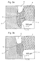
- FIGS. 3 a, b, c each show a schematic cross-section of the detail A in FIG Figure 1 or 2a-2d shown portion of the cavity body 1 after the thermal conduction welding by means of a Nd: YAG laser.
- the position of the heat conduction weld 12 corresponds to the position of the contact surface of the cover strip 4 on the leg 5 in the Figures 1 and 2 ad ,
- the surface of the heat conduction weld 12 is concave, so that a groove-like groove 13 is formed.
- the groove 13 merges in its edge regions into the underside of the cover strip 4 or into the inner surface of the leg 5.
- the joint 8 facing surface of the heat conduction weld 12 is also concave.
- Lid strip 4 and legs 5 have only a small connection cross-section, since the majority of the V-shaped joint 8 is still virtually unchanged after heat conduction welding and is unfilled.
- the concave surface shape is formed automatically due to surface tensions during and after heat conduction welding, respectively.
- the machining parameters for the three machining examples are shown in the following table.
- FIG. 4 shows a transverse section of the substantially same section as the FIGS. 3a-3c after re-welding the heat conduction weld 13 with a deep weld using a Nd: YAG laser.
- additional material in the form of filler wire was supplied during deep welding and the V-shaped joint was completely filled with a single weld.
- Lid strip 4 and legs 5 are in FIG. 4 connected via a connection cross-section which corresponds approximately to the thickness of the cover strip.
- the entire weld can be divided into two areas:
- the lower region comprises the heat conduction weld 12, which is arranged adjacent to the cavity 3.
- the heat conduction weld 12 has even after the second Koch facedung a groove 13 as in the Figures 3 ac on.
- the upper portion of the weld is formed by the deep weld 14, which begins at the cavity body outside and ends in the heat conduction weld 12.
- the deep weld 14 is formed to form a vapor capillary.
- the deep weld is funnel-shaped in cross-section. It reaches up to the heat conduction weld 12, or ends in this, but it does not penetrate the heat conduction weld 12. This is an indicator that even during deep welding the heat conduction weld 12 no spatter could penetrate from the vapor capillary 15 into the cavity 3.
- the cavity-side surface of the heat conduction weld 12 is convex. It is believed that this is a limiting case in which the heat conduction weld 12 is almost completely melted during deep welding and is convexly deformed by the pressure of the vapor capillary. However, in this case, the pressure of the vapor capillary is insufficient for the vapor capillary to open towards the cavity 3.
- FIG. 5 shows a cross section through a distributor ring 16 with four radial circumferential distribution channels 17 a, b, c, d.
- Two distribution channels 17 a, b are circumferentially outside and two distribution channels 17 c, d arranged inside circumferentially in the distribution ring 16.
- the channels can be arbitrarily arranged and configured differently, for example, instead of or in addition to the channels with radial openings and channels with axial openings.
- Each distribution channel 17 a, b, c, d is formed by a rectangular cross-section annular groove in the distribution ring 16, the radially outwardly or inwardly directed opening is closed by a welded cover strip 18 a, b, c, d.
- the annular grooves are limited in the axial direction by circumferential annular webs.
- Per cover channel 17 a, b, c, d, a cover strip 18 a, b, c, d is provided, which is welded with two radially circumferential welds on the associated annular webs.
- the ring lands and the cover strips 18 a, b, c, d have one of the impact geometries before welding as in the Figures 1, 2 ad shown.
- the cover strips are connected to the ring lands by heat conduction welding, resulting in a seam geometry, as exemplified in the Figures 3 ac shown.
- the cover band and ring lands are rewelded by laser deep welding with the addition of additional wire, wherein the heat conduction weld produced in the first step is again over-welded in its entire length. The result is a seam geometry as exemplified in Fig. 4 shown.
- cover strip 18 a, b, c, d is first fixed at all joints by thermal conduction welding and deep-welding takes place only after the fixation.
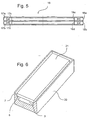
- FIG. 6 shows a container 20 with an attached cover 21 in the unwelded state in a perspective view, wherein for illustrating the impact geometry of the front portion is shown in sectional view.
- a rectangular in cross-section cavity 3 is formed.
- the lid 21 is first connected to the container 20 by a heat conduction weld around the lid 21 and in a second step by a deep weld. Both welds are done with a laser.
- Such welded containers are used for example in switchgear, wherein switching elements and a protective gas (SF 6 ) are provided in the containers.
- SF 6 protective gas
- cavity bodies for example cavity profiles as in FIG. 1 , Distribution rings as in FIG. 5 or container with lid as in FIG. 6 , the different impact geometries in the FIGS. 1, 2a-2d used in combination.
- the hollow body can straight or curved semi-finished products, eg
Abstract
Description
Die Erfindung betrifft ein Verfahren zum Verschweißen mindestens zweier vorzugsweise metallischer Bauteile mittels eines Energiestrahls, vorzugsweise eines Laserstrahls, entlang eines Schweißstoßes, sowie einen aus mindestens zwei Bauteilen zusammengesetzten Körper, vorzugsweise Hohlraumkörper, der vorzugsweise nach oben genanntem Verfahren hergestellt wird, sowie die Verwendung einer Laseranlage zur Herstellung eines derartigen zusammengesetzten Körpers.The invention relates to a method for welding at least two preferably metallic components by means of an energy beam, preferably a laser beam, along a weld joint, and a body composed of at least two components, preferably a hollow body, which is preferably produced by the above-mentioned method, and the use of a laser system for producing such a composite body.
Die Verwendung von aus mehreren metallischen Bauteilen zusammengesetzten Hohlraumkörpern in der Industrie ist weit verbreitet.The use of hollow bodies composed of several metallic components in the industry is widespread.
Ein bekanntes Anwendungsbeispiel für einen aus metallischen Bauteilen zusammengesetzten Hohlraumkörper ist ein Verteilerring für das Verteilen von Flüssigkeiten in Flaschen. Ein derartiger Verteilerring hat einen Durchmesser von bis zu 6 m und weist einen umlaufenden Verteilerkanal auf, der als Hohlkanal mit einer Vielzahl von Öffnungen ausgebildet ist. Die Öffnungen sind mit Zu- und Ableitungen bzw. mit Ventilen verbunden. Bei der Befüllung von Flaschen wird die Flüssigkeit in den Verteilerkanal eingebracht und über die Ventile in die Flaschen geleitet.One known application example of a cavity body composed of metallic components is a distribution ring for dispensing liquids in bottles. Such a distribution ring has a diameter of up to 6 m and has a circumferential distribution channel, which is formed as a hollow channel with a plurality of openings. The openings are connected to supply and discharge lines or with valves. When filling bottles, the liquid is introduced into the distribution channel and passed through the valves in the bottles.
Der Verteilerkanal wird durch eine radial umlaufende, im Querschnitt rechteckige Nut in dem Verteilerringkörper und einen auf den Verteilerringkörper als Deckel für die Nut aufgeschweißtes Band gebildet. Die Verschweißung von Deckelband mit dem Verteilerringkörper erfolgt bei den bekannten Verfahren über ein mehrlagiges WIG-Schweißen mit einer Schweißgeschwindigkeit von etwa 100 mm/min. Die Mehrlagigkeit der Schweißnaht ist erforderlich, um den Anbindungsquerschnitt zwischen Band und eigentlichem Verteilerring belastungsgerecht auszuführen, da während des Betriebs in den Verteilerkanälen große Drücke auftreten.The distribution channel is formed by a radially encircling, rectangular in cross-section groove in the Verteilerringkörper and welded onto the Verteilerringkörper as a cover for the groove band. The welding of cover strip with the distributor ring body is carried out in the known methods via a multi-layer TIG welding at a welding speed of about 100 mm / min. The multi-layered weld is required to the connection cross-section between the band and the actual distribution ring load-carrying, as occur during operation in the distribution channels large pressures.
Dieses bekannte Herstellungsverfahren für Verteilerringe weist als wesentliche Nachteile auf, dass die Bearbeitungszeit zum Aufschweißen der Bänder auf den Verteilerringkörper sehr lange ist und, dass der Verteilerring sich durch die Erwärmung während des langen Schweißvorgangs verzieht.This known manufacturing method for distributor rings has as significant drawbacks that the processing time for welding the bands on the distributor ring body is very long and that the distributor ring warps by the heating during the long welding operation.
Um die genannten Nachteile zu vermeiden wurde versucht das Deckelband und den Verteilerringkörper mittels Laserstrahlschweißen zu verbinden. Zwar wurden die oben genannten Probleme - lange Bearbeitungszeit und Verzug des Verteilerrings - stark verringert, es traten aber neue Probleme auf:In order to avoid the mentioned disadvantages, attempts were made to connect the cover band and the distributor ring body by means of laser beam welding. Although the above problems - long processing time and distortion of the distribution ring - were greatly reduced, but there were new problems:
Der Schweißstoß wurde, insbesondere im Bereich des Hohlraums des Verteilerkanals, nicht vollständig aufgeschmolzen, so dass im Fußbereich des Schweißstoßes zum Hohlraum hin geöffnete Spalten zwischen Deckel und Ring verbleiben. Diese Spalten verhindern eine effektive Reinigung des Verteilerkanals, da sich in den Spalten Schmutzpartikel festsetzen können. Weiterhin kann bei Belastung die durch die Spalten auftretende Kerbwirkung zu einem Versagen der Laserschweißnaht führen.The weld joint has not been completely melted, in particular in the region of the cavity of the distributor channel, so that gaps left in the foot region of the weld joint between the lid and the ring remain open to the cavity. These gaps prevent effective cleaning of the distribution channel, as dirt particles can accumulate in the gaps. Furthermore, under load, the notch effect occurring through the gaps can lead to a failure of the laser weld seam.
Als weiteres Problem wurde erkannt, dass der Hohlraum durch die beim Laserstrahltiefschweißen entstehende und zum Hohlraum - also zum Verteilerkanal - hin geöffnete Dampfkapillare durch Schweißspritzer stark verschmutzt wird, da durch die Dampfkapillare Schweißspritzer, Rauch und Schmauch austreten.A further problem has been recognized that the cavity is heavily contaminated by the spatter caused by the laser beam deep welding and to the cavity - ie to the distribution channel - open steam capillary, as spilled by the Dampfkapillare spatter, smoke and smoke.
Das Problem mit den verbleibenden Spalten sowie die Verschmutzungen des Hohlraums durch Schweißspritzer bei der Fertigung führen dazu, dass Verteilerringe, die mit dem bekannten Laserschweißverfahren hergestellt werden z. B. nicht im Bereich der Lebensmittelindustrie eingesetzt werden können.The problem with the remaining gaps as well as the contamination of the cavity by welding spatter during manufacture lead to distributor rings, which are produced by the known laser welding method z. B. can not be used in the food industry.
Bekannt sind auch Gehäuse für elektrische Schaltanlagen. Die Gehäuse sind in Plattenbauweise aufgebaut. Bei der Herstellung der Gehäuse wird zur Verbindung der Platten heute Laserschweißen eingesetzt. Um zu verhindern, daß in das Gehäuseinnere Schweißemissionen eintreten, wird die Schweißnaht unter einem spitzen Winkel zur Fuge, häufig vorzugsweise 5°, eingebracht. Das Eindringen von Emissionen in den Gehäuseinnenraum läßt sich auf diese Weise aber nicht zuverlässig verhindern.Also known are housings for electrical switchgear. The housings are constructed in plate construction. In the manufacture of the housing laser welding is used today for connecting the plates. To prevent that in the Housing internal welding emissions occur, the weld at an acute angle to the joint, often preferably 5 °, introduced. The penetration of emissions into the housing interior can not be reliably prevented in this way.
Es ist Aufgabe dieser Erfindung, ein Verfahren zum Verschweißen zweier vorzugsweise metallischer Bauteile mittels eines Energiestrahls, vorzugsweise eines Laserstrahls, vorzuschlagen, das die genannten Probleme des Standes der Technik überwindet. Weiterhin ist es Aufgabe der Erfindung einen entsprechenden, aus mehreren Bauteilen zusammengesetzten Körper, vorzugsweise Hohlraumkörper und eine entsprechende Laseranlage zur Herstellung eines solchen zusammengesetzten Körpers vorzuschlagen.It is an object of this invention to propose a method for welding two preferably metallic components by means of an energy beam, preferably a laser beam, which overcomes the aforementioned problems of the prior art. It is another object of the invention to propose a corresponding, composed of several components body, preferably cavity body and a corresponding laser system for producing such a composite body.
Die Aufgaben werden gelöst durch die Gegenstände der unabhängigen Ansprüche 1 und 15.The objects are achieved by the subject-matter of independent claims 1 and 15.
Bei dem erfindungsgemäßen Verfahren zum Verschweißen zweier vorzugsweise metallischer Bauteile - im folgenden auch Werkstücke genannt - mittels eines Energiestahls, vorzugsweise eines Laserstrahls, entlang eines Schweißstoßes, ist vorgesehen, dass der Schweißstoß eine zu der vom Schweißkopf zugewandten Seite hin geöffnete Fuge und einen im Bereich des Fußes der Fuge angeordneten Anlagebereich aufweist, in dem die Bauteile aneinander anliegen und der den Schweißstoß an der vom Schweißkopf abgewandten Seite abschließt, wobei in einem ersten Verfahrensschritt die Bindepartner im Anlagebereich durch Wärmeleitungsschweißen unter Ausbildung einer Wärmeleitungsschweißnaht verbunden werden und in einem zweiten Verfahrensschritt die Bindepartner im Bereich der Fuge und entlang der Wärmeleitungsschweißnaht durch Laserstrahl-oder Elektronenstrahlschweißen, vorzugsweise Laserstrahl- oder Elektronenstrahltiefschweißen, verbunden werden, wobei die Wärmeleitungsschweißnaht verhindert, dass Prozessemissionen, insbesondere Schweißspritzer, Rauch oder Schmauch, beim Laserstrahl- oder Elektronenstrahlschweißen an der Werkstückinnenseite austreten.In the method according to the invention for welding two preferably metallic components - hereinafter also referred to as workpieces - by means of an energy steel, preferably a laser beam, along a weld joint, it is provided that the weld joint opens a joint open to the side facing the welding head and one in the region of Has foot of the joint arranged abutment area in which the components abut each other and which closes the weld joint on the side facing away from the welding head, wherein in a first process step, the binding partners are connected in the investment area by thermal conduction welding to form a heat conduction weld and in a second process step the binding partners in Area of the joint and along the heat conduction weld by laser beam or electron beam welding, preferably laser beam or electron beam deep welding, are connected, wherein the heat conduction weld ve prevents process emissions, in particular spatter, smoke or smoke from escaping at the inside of the workpiece during laser beam or electron beam welding.
Die zu verbindenden Werkstücke sind vorzugsweise aus Metall ausgebildet, können aber auch aus Kunststoff oder anderen Materialien bestehen.The workpieces to be joined are preferably made of metal, but may also consist of plastic or other materials.
Zur Erzeugung des Energiestrahls wird vorzugsweise eine Laseranlage, insbesondere eine Nd:YAG -, Dioden - oder CO2- Laseranlage, verwendet, bei abgewandelten Ausführungsformen des Verfahrens können aber auch Elektronenstrahlschweißanlagen zur Erzeugung des Energiestrahls eingesetzt werden.For generating the energy beam, preferably a laser system, in particular a Nd: YAG, diode or CO 2 laser system, is used, but in modified embodiments of the method, electron beam welding systems can also be used to generate the energy beam.
Die Werkstücke d.h. die zu verbindenden Bauteile werden aneinander anstoßend angeordnet, wobei zwischen den Werkstücken ein zu verschweißender Stoß - der Schweißstoß - gebildet wird. Der Schweißstoß wird bei den späteren Verfahrensschritten in Längsrichtung, also entlang der Längserstreckung geschweißt. In Quererstreckung umfasst der Schweißstoß eine zu der zum Schweißkopf zugewandten Seite hin geöffnete Fuge und einen am unteren Ende, also gegenüber der Öffnung der Fuge angeordneten, angeschlossenen Anlagebereich, in welchem die zwei zu verschweißenden Bauteile aneinander anliegen, also in Kontakt miteinander sind. Dieser Anlagebereich endet an der Werkstückinnenseite.The workpieces i. the components to be joined are arranged abutting one another, wherein between the workpieces to be welded joint - the weld joint - is formed. The weld joint is welded in the later process steps in the longitudinal direction, ie along the longitudinal extent. In transversal extension, the weld joint comprises a joint open to the side facing the welding head and a contact region connected to the lower end, ie opposite the opening of the joint, in which the two components to be welded abut each other, ie are in contact with each other. This contact area ends at the workpiece inside.
Bei dem ersten Verfahrensschritt wird durch vorzugsweise einen durch die zum Schweißkopf zugewandten Seite hin geöffnete Fuge eintretenden Energiestrahl der Anlagebereich vorzugsweise vollständig verschweißt, so dass an der Stelle des Anlagebereichs eine Wärmeleitungsschweißnaht entsteht.In the first method step, the energy beam of the contact region which preferably enters through a gap which is opened through the side facing the welding head is preferably completely welded, so that a heat conduction weld is formed at the location of the contact region.
Bei dem zweiten Verfahrensschritt wird der gleiche Abschnitt des Schweißstoßes wie beim Wärmeleitungsschweißen nochmals mit einem Energiestrahl überfahren, wobei die Bauteile im Bereich der Fuge vorzugsweise durch Wärmeleitungs- oder Tiefschweißen verbunden werden.In the second method step, the same section of the weld joint is again passed over by an energy beam as in the case of heat conduction welding, wherein the components in the region of the joint are preferably connected by heat conduction or deep welding.
Die Begriffe "Wärmeleitungsschweißen" und "Tiefschweißen" sind aus der Lasertechnik bekannt und sollen im Sinn der Lasertechnik verstanden werden. Ausführungen und Erläuterungen zu diesen Begriffen sind z.B. in der Dissertation von
-
Strahlwerkzeug Laser, Prof. H. Hügel; B.G. Teubner Stuttgart 1992 -
Beck, M. Dausinger, F. Hügel, H.: Modellvorstellungen zur Energieeinkoppelung von Laserstrahlen in Materie, in: Schweißtechnische Fertigungsverfahren Schutztechnik-Lichtbogentechnik. Düsseldorf: DVS.1989, S. 43-47 - Skript zur Vorlesung "Lasertechnik I + II" 2003, von Prof. R. Poprawe, Lehrstuhl für Lasertechnik RWTH Aachen.
-
Laser beam tool, Prof. H. Hügel; BG Teubner Stuttgart 1992 -
Beck, M. Dausinger, F. Hügel, H .: Model ideas for the energy coupling of laser beams into matter, in: Welding technology manufacturing techniques Protection technology arc technology. Dusseldorf: DVS.1989, pp. 43-47 - Script for the lecture "Laser Technology I + II" 2003, by Prof. R. Poprawe, Department of Laser Technology RWTH Aachen.
Die beim ersten Verfahrensschritt erzeugte Wärmeleitungsschweißnaht verhindert, dass die beim zweiten Verfahrensschritt im Falle des Tiefschweißens entstehende Dampfkapillare sich zur Werkstückinnenseite hin öffnet und verhindert, dass Prozessemissionen, insbesondere Schweißspritzer, Rauch oder Schmauch an der Werkstückinnenseite austreten. Die beim Tiefschweißen entstehende Dampfkapillare ist in Richtung zu der vom Schweißkopf abgewandten Seite d.h. vorzugsweise die Werkstückinnenseite durch die Wärmeleitungsschweißnaht begrenzt.The heat conduction weld produced during the first process step prevents the vapor capillary formed in the second process step in the case of deep welding from opening to the inside of the work piece and prevents process emissions, in particular spatter, smoke or smoke from escaping from the inside of the work piece. The resulting during deep welding vapor capillary is in the direction of the side facing away from the welding head, ie. preferably the workpiece inside limited by the heat conduction weld.
Das Verfahren ist vorteilhaft ausgeführt, wenn der Energiestrahl von der Werkstückaußenseite zugeführt wird. Dies ist bspw. der Fall, wenn der Energiestrahl durch die zur Werkstückaußenseite geöffnete Fuge eintritt.The method is advantageously carried out when the energy beam is supplied from the workpiece outside. This is the case, for example, when the energy beam enters through the gap open to the workpiece exterior.
Bei dem zweiten Verfahrensschritt kann das Materialfehlvolumen des Schweißstoßes im Bereich der Fuge entweder durch Abschmelzen des stoßumliegenden Materials der Werkstücke oder durch Zusatzwerkstoff, vorzugsweise Pulver, Zusatzdraht etc. gefüllt werden. Der Zusatzwerkstoff kann entweder während des Schweißens automatisiert zugeführt werden oder als Zusatzmaterial vor dem zweiten Verfahrensschritt in die Fuge eingelegt werden.In the second method step, the material mis-volume of the weld joint in the region of the joint can be filled either by melting the material of the material in contact with the excess material or by additional material, preferably powder, filler wire, etc. The filler material can be either automatically fed during welding or inserted as a filler before the second step in the joint.
Bei vorteilhaften Weiterbildungen des Verfahrens wird der Wärmeleitungsschweißprozess so geführt, dass die Bauteile durch die Wärmeleitungsschweißnaht zueinander fixiert sind. Diese Fixierung und/oder der vergleichsweise geringe Energieeintrag während des zweiten Verfahrensschritts führt dazu, dass der Verzug des Bauteils sehr gering gehalten wird.In advantageous developments of the method of the heat conduction welding process is performed so that the components are fixed to each other by the heat conduction weld. This fixation and / or the comparatively low energy input during the second process step means that the distortion of the component is kept very low.
Das Verfahren ist vorteilhaft ausgebildet, wenn der Wärmeleitungsschweißprozess so geführt wird, dass durch die Wärmeleitungsschweißnaht der Schweißstoß an der vom Schweißkopf abgewandten Seite, d.h. vorzugsweise der Werkstückinnenseite versiegelt ist. Dies ist insbesondere der Fall, wenn durch das Wärmeleitungsschweißen eine gleichmäßige glatte Schweißraupe an der Werkstückunterseite erzeugt wird. Die Versiegelung verhindert, dass Schmutzpartikel aus dem Schweißstoß zur Werkstückinnenseite hin austreten.The method is advantageously formed when the heat conduction welding process is performed so that the weld joint on the side facing away from the welding head by the heat conduction weld, i. preferably the workpiece inside is sealed. This is the case in particular if a uniform, smooth welding bead is produced on the underside of the workpiece by the heat conduction welding. The seal prevents dirt particles from escaping from the weld joint to the inside of the workpiece.
Es liegt eine vorteilhafte Ausgestaltung des Verfahrens vor, wenn der Wärmeleitungsschweißprozess so geführt ist, dass an der vom Schweißkopf abgewandten Seite, vorzugsweise der Werkstückinnenseite eine spaltfreie und/oder konkave Oberfläche ausgebildet wird. Eine derartige Ausbildung der Oberfläche verringert die Kerbwirkung und verhindert das Absetzen von Schmutzpartikeln an der vom Schweißkopf abgewandten Seite des Werkstückes, d.h. vorzugsweise der Werkstückinnenseite. Die Ausbildung der Wärmeleitungsschweißnaht an der betreffenden Werkstückseite, d.h. vorzugsweise Werkstückunterseite kann durch den Einsatz von geeigneten Formiergasen - z. B. He, Ar, H2, N2 oder Gemische dieser Gase - unterstützt werden.There is an advantageous embodiment of the method, when the heat conduction welding process is performed so that at the side facing away from the welding head side, preferably the workpiece inside a gap-free and / or concave surface is formed. Such a design of the surface reduces the notch effect and prevents the deposition of dirt particles on the side facing away from the welding head side of the workpiece, ie preferably the workpiece inside. The formation of the heat conduction weld on the relevant workpiece side, ie preferably workpiece underside can by the use of suitable Formiergasen -. As He, Ar, H 2 , N 2 or mixtures of these gases - be supported.
Es liegt eine bevorzugte Ausführungsform des Verfahrens vor, wenn die Fuge V-förmig ausgebildet ist. Diese Ausbildung kann durch eine Abschrägung, Abrundung oder Abstufung von einen oder von beiden Werkstücken bzw. einer Fase bei einem oder beiden Werkstücken im Bereich des Schweißstoßes erreicht werden.There is a preferred embodiment of the method, when the joint is V-shaped. This training can be achieved by a bevel, rounding or grading of one or both workpieces or a chamfer at one or both workpieces in the region of the weld joint.
Die V-förmige Fuge kann einen Öffnungswinkel zwischen 15 und 45°, vorzugsweise zwischen 20 und 40° und insbesondere zwischen 25 und 35° aufweisen, wobei bei den Angaben von einem Vollwinkel ausgegangen wird. Der Öffnungsvollwinkel sollte größer als der Kaustikwinkel des einfallenden Laserstrahls ausgebildet sein, damit der Laserstrahl ohne zu große Absorption an den Fugenwänden bis in den Anlagebereich vordringen kann.The V-shaped joint may have an opening angle between 15 and 45 °, preferably between 20 and 40 ° and in particular between 25 and 35 °, wherein the information is based on a full angle. The full opening angle should be greater than the Kaustikwinkel of the incident laser beam, so that the laser beam can penetrate without too much absorption at the joint walls into the investment area.
Bei abgewandelten Ausführungsformen kann die Fuge im Querschnitt im wesentlichen rechteckig ausgebildet sein, wobei vorzugsweise der Durchmesser des Laserstrahls im Anfangsbereich der Fuge kleiner die Breite der Fuge ausgebildet ist.In modified embodiments, the joint may be formed substantially rectangular in cross section, wherein preferably the diameter of the laser beam in the initial region of the joint is smaller the width of the joint is formed.
Bei bevorzugten Ausführungsformen ist vorgesehen, dass der Anlagebereich, also der Kontaktbereich zwischen den Werkstücken, flächig ausgebildet ist. Dieser flächige Anlagebereich ist in seinen Abmessungen so dimensioniert, dass er beim Wärmeleitungsschweißen vollständig aufgeschmolzen wird. Bei abgewandelten Ausführungsformen ist vorgesehen, die Stoßgeometrie so auszuführen, dass die an den Anlagebereich angrenzenden Massen der Werkstücke so verteilt sind, dass die Wärmeableitung vom Anlagebereich in die Werkstücke bei beiden Werkstücken in etwa gleich stark ist.In preferred embodiments, it is provided that the abutment region, that is to say the contact region between the workpieces, is of planar design. This flat contact area is dimensioned in its dimensions so that it is completely melted during heat conduction welding. In modified embodiments, it is provided to design the impact geometry such that the masses of the workpieces adjacent to the abutment region are distributed in such a way that the heat dissipation from the abutment region into the workpieces is approximately the same for both workpieces.
Vorzugsweise wird das Verfahren verwendet, um zwei Werkstücke zu verbinden, die einen Hohlraum bilden, wobei die Werkstückinnenseite dem Hohlraum zugewandt ist. Der Hohlraum kann ein vollständig abgeschlossener oder ein mit mehreren Öffnungen und/oder Durchbrüchen versehener Hohlraum sein. Das Verfahren findet auch Anwendung für die Verbindung von Werkstücken, wobei der Schweißstoß von einer Seite, insbesondere der Werkstückinnenseite, für den Energiestrahl schwer oder nicht zugänglich ist.
Insbesondere kann das Verfahren für die Herstellung eines Verteilerrings der eingangs beschriebenen Art Verwendung finden, der aus einem Verteilerringkörper mit umlaufender Nut und einem Band besteht, wobei das Band zum Verschließen der Nut auf den Verteilerringkörper aufgeschweißt wird. Der Verteilerring kann auch mehrere Verteilerkanäle aufweisen.Preferably, the method is used to join two workpieces forming a cavity with the workpiece inside facing the cavity. The cavity may be a completely closed or a multi-apertured and / or apertured cavity. The method also finds application for the connection of workpieces, wherein the welding impact from one side, in particular the workpiece inner side, is difficult or impossible for the energy beam.
In particular, the method for the production of a distribution ring of the type described above can be used, which consists of a distributor ring body with circumferential groove and a band, wherein the tape is welded to close the groove on the distributor ring body. The distribution ring may also have multiple distribution channels.
Die der Erfindung zugrundeliegende Aufgabe wird weiterhin mit dem aus mehreren Bauteilen zusammengesetzten Körper gemäß Anspruch 15 gelöst. Vorzugsweise kann es sich um einen Hohlraumkörper handeln, der aus einem Grundkörper und einem Deckel besteht, die zusammen einen Hohlraum bilden und mit mindestens einer Laserschweißnahtanordnung miteinander verbunden sind, wobei die Laserschweißnahtanordnung sich durchgehend von der Außenseite des Hohlraumkörpers bis zum Hohlraum erstreckt, wobei die Laserschweißnahtanordnung vorzugsweise aus einer Wärmeleitungsschweißnaht und einer Tiefschweißnaht besteht und wobei vorgesehen ist, dass die Wärmeleitungsschweißnaht an dem Hohlraum angrenzend ausgebildet ist und die Tiefschweißnaht durch die Wärmeleitungsschweißnaht zum Hohlraum hin begrenzt ist.The object underlying the invention is further achieved with the composite of several components body according to claim 15. Preferably, it may be a cavity body consisting of a body and a lid which together form a cavity and interconnected with at least one laser weld assembly, the laser weld assembly extending continuously from the outside of the cavity body to the cavity, the laser weld assembly preferably from a heat conduction weld and a deep weld, and wherein it is provided that the heat conduction weld is formed adjacent to the cavity and the deep weld is limited by the heat conduction weld to the cavity.
Die Laserschweißnahtanordnung ist als eine Aneinanderreihung einer ersten und einer zweiten Schweißnaht, vorzugsweise einer Wärmeleitungsschweißnaht und einer Tiefschweißnaht ausgeführt, wobei die Laserschweißnahtanordnung mit der Tiefschweißnaht im Falle des Hohlkörpers an der Außenseite des Hohlkörpers beginnt. An die Tiefschweißnaht direkt angeschlossen ist die Wärmleitungsschweißnaht, die mit ihrem Endabschnitt an den Hohlraum des Hohlraumkörpers unmittelbar angrenzt. Der Tiefschweißeffekt und damit die Herstellung der Tiefschweißnaht wird durch Ausbildung einer Dampfkapillare erreicht. Die Einschweißtiefe ist größer gleich der Eindringtiefe der Dampfkapillaren. An den Wänden der Dampfkapillare wird die Laserstrahlung absorbiert. Es entsteht ein die Dampfkapillare umschließendes Schmelzebad, das nach der Erstarrung die Tiefschweißnaht ausbildet. Die Tiefschweißnaht dringt in die Wärmeschweißnaht ein, durchdringt sie jedoch nicht vollständig.The laser weld seam arrangement is designed as a juxtaposition of a first and a second weld seam, preferably a heat conduction weld seam and a deep weld seam, wherein the laser weld seam assembly begins with the deep weld seam in the case of the hollow body on the outside of the hollow body. Directly connected to the deep weld is the heat pipe weld, which immediately adjoins the cavity of the cavity body with its end portion. The deep welding effect and thus the production of the deep weld is achieved by forming a vapor capillary. The penetration depth is greater than or equal to the penetration depth of the vapor capillaries. The laser radiation is absorbed on the walls of the vapor capillary. The result is a steam bath surrounding the melt bath, which forms the deep weld after solidification. The deep weld penetrates the heat weld, but does not penetrate it completely.
Bei bevorzugten Ausführungsformen ist vorgesehen, dass der an den Hohlraum angrenzende Oberflächenabschnitt der Wärmeleitungsschweißnaht konkav ausgebildet ist. Die konkave Oberfläche verhindert sehr effektiv eine Ablagerung von Schmutzpartikeln und erleichtert die Reinigung des Hohlraums. Weiterhin vermindert die konkave Oberfläche die Kerbwirkung an der Fügestelle durch angreifende Kräfte.In preferred embodiments, provision is made for the surface section of the heat conduction weld seam adjoining the cavity to be concave. The concave surface very effectively prevents deposition of dirt particles and facilitates cleaning of the cavity. Furthermore, the concave surface reduces the notch effect at the joint by attacking forces.
Vorzugsweise handelt es sich bei dem Hohlraumkörper um einen Verteilerring der eingangs beschriebenen Art.Preferably, the cavity body is a distribution ring of the type described above.
Die Laseranlage weist vorzugsweise eine Führungsmaschine, insbesondere eine kartesische Führungsmaschine oder einen Roboter auf, um den Schweißkopf relativ zum Werkstück präzise geführt zu bewegen. Hierbei kann alleine der Schweißkopf oder alleine das Werkstück oder beide bewegt werden.The laser system preferably has a guiding machine, in particular a Cartesian guiding machine or a robot, relative to the welding head to move the workpiece precisely guided. In this case alone, the welding head or alone the workpiece or both can be moved.
Bei bevorzugten Ausführungsformen weist die Laseranlage Spannmittel auf, mit der die beiden Werkstücke zueinander fixiert werden. Bei den Spannmitteln kann es sich um statische Spannmittel, z.B. Spannklauen, oder dynamische Spannmittel, z.B. Andruckrollen oder Andruckfinger, die mit dem Energiestrahl mitbewegt werden, handeln.In preferred embodiments, the laser system on clamping means with which the two workpieces are fixed to each other. The tensioning means may be static tensioning means, e.g. Clamping jaws, or dynamic clamping means, e.g. Pressure rollers or Andruckfinger, which are moved with the energy beam act.
Die Laseranlage weist ein Laseraggregat auf, das vorzugsweise aus einem CO2-oder Nd:YAG-Laser oder einen Diodenlaser oder einen CO2-Laser mit einer Ausgangsleistung über 1.000 Watt gebildet ist.The laser system has a laser aggregate, which is preferably formed from a CO 2 or Nd: YAG laser or a diode laser or a CO 2 laser with an output power of more than 1,000 watts.
Bei vorteilhaften Weiterbildungen der Laseranlage weist diese einen Stossverfolgungssensor auf, der die Lage des Schweißstoßes sensorisch erfasst. Der Sensor kann als optischer - insbesondere als Lichtschnittsensor - oder als taktiler Sensor ausgebildet sein. Die gemessenen Sensorwerte werden entweder On-Line, d.h. während der laufenden Bearbeitung, oder Off-Line, d.h. vor der Bearbeitung mit einer programmierten Bearbeitungsbahn verrechnet oder bilden die Grundlage für die Erstellung einer Bearbeitungsbahn.In advantageous developments of the laser system, this has a shock-tracking sensor, which senses the position of the weld joint. The sensor can be designed as an optical - in particular as a light section sensor - or as a tactile sensor. The measured sensor values are either on-line, i. during ongoing processing, or off-line, i. Before machining, they are offset against a programmed machining path or form the basis for creating a machining path.
Weitere Merkmale und Einzelheiten der Erfindung sind anhand der nachfolgenden Zeichnungen und Beschreibungen dargestellt. Es zeigen:
- Figur 1
- eine schematische Schnittansicht eines Hohlraumprofils mit Deckblech als ein erstes Ausführungsbeispiel eines Hohlraumkörpers;
- Figur 2a,b,c,d
- jeweils eine Ausschnittsvergrößerung des Details A in
Figur 1 mit abgewandelten Ausführungen der Stoßgeometrie; - Figur 3a,b,c
- jeweils einen Querschliff des Details A in
Figur 1 nach dem Wärmeleitungsschweißen in schematischer Darstellung; Figur 4- einen Querschliff des Details A in
Figur 1 nach dem Tiefschweißvorgang in schematischer Darstellung; Figur 5- eine schematische Schnittansicht eines Verteilerrings als ein zweites Ausführungsbeispiel eines Hohlraumkörpers;
Figur 6- eine schematische perspektivische Darstellung eines rechteckigen Behälters mit Deckel als drittes Ausführungsbeispiel eines Hohlraumkörpers.
- FIG. 1
- a schematic sectional view of a cavity profile with cover plate as a first embodiment of a cavity body;
- Figure 2a, b, c, d
- in each case a detail enlargement of the detail A in
FIG. 1 with modified versions of the butt geometry; - FIG. 3a, b, c
- one cross-section of detail A in each case
FIG. 1 after heat conduction welding in a schematic representation; - FIG. 4
- a cross-section of detail A in
FIG. 1 after the deep welding process in a schematic representation; - FIG. 5
- a schematic sectional view of a distribution ring as a second embodiment of a cavity body;
- FIG. 6
- a schematic perspective view of a rectangular container with lid as a third embodiment of a cavity body.
Das U-Profil 2 besteht aus einem rechteckigen Grundkörper, an den zwei zueinander parallele und zueinander spiegelsymmetrische Schenkel 5 angeordnet sind, wobei Grundkörper und Schenkel 5 in der Darstellung in
Die beiden Schenkel 5 weisen an ihren zum Hohlraum 3 gerichteten Innenseiten jeweils eine Stufe mit einem waagrechten, parallel zum Boden des Hohlraums 3 ausgerichteten Auflageabsatz 6 auf. Die Auflageabsätze 6 sind auf den Schenkeln 5 gegenüberliegend in gleicher Höhe angeordnet.The two
Die an die Auflageabsätze 6 anschließenden Schenkelendabschnitte sind jeweils an der Innenseite unter Ausbildung einer Fase 7 angeschrägt. Die Fasen 7 sind voneinander divergierend ausgerichtet. Zwischen der Fase 7 und dem Auflageabsatz 6 ist jeweils ein stumpfer Winkel alpha von etwa 120° ausgebildet. Die Fase 7 schließt sich jeweils unmittelbar an den Auflageabsatz 6 unter Ausbildung einer Kante 22 an und erstreckt sich bis zum distalen Ende des Schenkels 5.The adjoining the
Das Deckelband 4 ist im Querschnitt rechteckig ausgebildet und ist liegend auf die Aufnahmeabsätze 6 des U-Profils 2 angeordnet, wobei die Innenseiten des U-förmigen Profils 2 und die Unterseite des Deckelbands 4 den im Querschnitt rechteckigen Hohlraum 3 bilden. Die Randbereiche der Unterseite - also der zum Hohlraum 3 gewandten Seite - des Deckelbands 4 und die Auflageabsätze 6 des U-Profils 2 sind miteinander in flächigen Kontakt. Das Deckelband 4 liegt auf den Auflageabsätzen 6 beidseitig abgestützt auf, wobei die linke Unterkante des Deckelbands 4 nahe zur Kante 22 des linken Auflageabschnitts 6 und die rechte Unterkante des Deckelbands 4 nahe zur Kante 22 des rechten Auflageabsatzes 6 anliegt. Die Toleranz für die Breite des Deckelbandes wird durch die Breite des Auflageabsatzes festgelegt. Die Breite darf maximal den Abstand der Kanten 22 zueinander betragen. Das Minimalmaß der Deckelbreite errechnet sich aus der Breite des Hohlraums zuzüglich der Breite des Auflageabsatzes 6 zuzüglich ca. 0,2 mm.The
Wie in
Wie später noch detaillierter erläutert wird, wird das Deckelband 4 mit dem U-Profil 2 im Bereich der Auflageabsätze 6, die die Auflage für das Deckelband 4 bilden, in einem ersten Schritt durch Wärmeleitungsschweißen stoffschlüssig verbunden. Die V-förmige Fuge wird in einem zweiten Bearbeitungsschritt durch Lasertiefschweißen geschlossen. Bei beiden Bearbeitungsschritten wird der Laserstrahl von der Hohlraumkörperaußenseite in die Fuge 8 eingestrahlt.As will be explained in more detail later, the
Anhand der
In der
Es sind jeweils ein Ausschnitt des Schenkels 5 und ein Ausschnitt des Deckelbands 4 gezeigt, die durch eine Wärmeleitungsschweißnaht 12 stoffschlüssig miteinander verbunden sind.In each case, a section of the
Die Position der Wärmeleitungsschweißnaht 12 entspricht der Position der Anlagefläche des Deckelbands 4 an den Schenkel 5 in den
Auf Seiten des Hohlraums 3 ist die Oberfläche der Wärmeleitungsschweißnaht 12 konkav ausgebildet, so dass sich eine rinnenartige Hohlkehle 13 bildet. Die Hohlkehle 13 geht in ihren Randbereichen in die Unterseite des Deckelbands 4 bzw. in die Innenfläche des Schenkels 5 über.On the side of the
Die der Fuge 8 zugewandte Oberfläche der Wärmeleitungsschweißnaht 12 ist ebenfalls konkav ausgebildet. Deckelband 4 und Schenkel 5 weisen nur einen geringen Anbindungsquerschnitt auf, da der Großteil der V-förmigen Fuge 8 nach dem Wärmeleitungsschweißen noch nahezu unverändert erhalten und ungefüllt ist.The joint 8 facing surface of the
Es wird vermutet, dass sich die konkave Oberflächenform aufgrund von Oberflächenspannungen während bzw. nach dem Wärmeleitungsschweißen selbsttätig ausbildet.It is believed that the concave surface shape is formed automatically due to surface tensions during and after heat conduction welding, respectively.
Die Bearbeitungsparameter für die drei Bearbeitungsbeispiele sind der nachfolgenden Tabelle zu entnehmen.The machining parameters for the three machining examples are shown in the following table.
Die
Deckelband 4 und Schenkel 5 sind in
Die gesamte Schweißnaht kann in zwei Bereiche unterteilt werden:The entire weld can be divided into two areas:
Der untere Bereich umfasst die Wärmeleitungsschweißnaht 12, die angrenzend zum Hohlraum 3 angeordnet ist. Die Wärmeleitungsschweißnaht 12 weist auch nach der zweiten Überschweißung eine Hohlkehle 13 wie in den
Der obere Bereich der Schweißnaht wird durch die Tiefschweißnaht 14 gebildet, die an der Hohlraumkörperaußenseite beginnt und in der Wärmeleitungsschweißnaht 12 endet. Die Tiefschweißnaht 14 ist unter Bildung einer Dampfkapillare gebildet. Die Tiefschweißnaht ist im Querschnitt trichterförmig ausgebildet. Sie reicht bis an die Wärmeleitungsschweißnaht 12 heran, bzw. endet in dieser, aber sie durchdringt die Wärmeleitungsschweißnaht 12 nicht. Dies ist ein Indikator dafür, dass auch während des Tiefschweißens die Wärmeleitungsschweißnaht 12 keine Schweißspritzer aus der Dampfkapillare 15 in den Hohlraum 3 eindringen konnten.The upper portion of the weld is formed by the
Bei anders gewählten Bearbeitungsparametern, wie z.B. höheren Streckenenergien beim Lasertiefschweißen, ist die hohlraumseitige Oberfläche der Wärmeleitungsschweißnaht 12 konvex ausgebildet. Es wird vermutet, dass es sich hierbei um einen Grenzfall handelt, bei dem die Wärmeleitungsschweißnaht 12 während des Tiefschweißens fast vollständig aufgeschmolzen wird und durch den Druck der Dampfkapillare konvex verformt wird. Der Druck der Dampfkapillare reicht jedoch in diesem Fall nicht dazu aus, dass sich die Dampfkapillare zum Hohlraum 3 hin öffnet.With otherwise selected processing parameters, such as higher line energies in laser deep welding, the cavity-side surface of the
Jeder Verteilerkanal 17 a,b,c,d wird durch eine im Querschnitt rechteckige Ringnut im Verteilerring 16 gebildet, deren radial nach außen bzw. nach innen gerichtete Öffnung durch ein aufgeschweißtes Deckelband 18 a,b,c,d verschlossen ist. Die Ringnuten sind in axialer Richtung durch umlaufende Ringstege begrenzt.
Pro Verteilerkanal 17 a,b,c,d ist ein Deckelband 18 a,b,c,d vorgesehen, das mit jeweils zwei radial umlaufenden Schweißnähten auf die zugehörigen Ringstege aufgeschweißt ist.Each
Per
Die Ringstege und die Deckelbänder 18 a,b,c,d weisen vor dem Verschweißen eine der Stoßgeometrien auf wie in den
Es ist vorteilhaft, wenn das Deckelband 18 a,b,c,d zunächst an allen Verbindungsstellen durch Wärmeleitungsschweißen fixiert wird und erst nach der Fixierung das Tiefschweißen erfolgt.It is advantageous if the
Der Bereich in dem der Deckel 21 auf dem Behälter 20 aufliegt ist nahezu identisch zu der in
Derartige verschweißte Behälter werden beispielsweise im Schaltanlagenbau verwendet, wobei in den Behältern Schaltelemente und ein Schutzgas (SF6) vorgesehen sind.Such welded containers are used for example in switchgear, wherein switching elements and a protective gas (SF 6 ) are provided in the containers.
Bei weiteren Ausführungsformen von Hohlraumkörpern, z.B. Hohlraumprofile wie in
Bänder oder Profilträger, mit genannten Profil aufweisen, die zu kreisförmigen, elliptischen Ringen oder Vielecken, z.B. Rechtecken, zusammengesetzt sind.Belts or profiled beams, with said profile, which form circular, elliptical rings or polygons, e.g. Rectangles are composed.
Claims (20)
- Process for welding at least two preferably metallic components (2, 4, 20, 21) by means of an energy beam, preferably a laser beam, along a welding joint, the welding joint having a groove (8) which is open towards the side facing towards the welding head and having an abutting region (6) which is arranged in the region of the base of the groove (8) and in which the components abut one another and which terminates the welding joint on the side facing away from the welding head, wherein
in a first process step, the components (2, 4, 20, 21) are joined in the abutting region (6) by heat conduction welding to form a heat conduction weld (12), the energy beam being supplied from the side facing towards the welding head during the heat conduction welding, and
in a second process step, the components are joined in the region of the groove and along the heat conduction weld by deep penetration laser-beam or electron-beam welding, the energy beam being supplied from the side facing towards the welding head during the deep penetration welding, the heat conduction weld (12) preventing process emissions, namely welding spatter, smoke or fumes, from emerging on the side of the weld facing away from the welding head during the laser-beam or electron-beam welding. - Process according to Claim 1, characterized in that filler material, preferably powder, in particular filler wire, is used in the laser-beam or electron-beam welding and/or a vapour capillary is formed during the laser-beam or electron-beam welding.
- Process according to one of the preceding claims, characterized in that a laser unit, an electron-beam unit or a TIG welding unit or an MIG welding unit or an MAG welding unit is used for the heat conduction welding.
- Process according to one of the preceding claims, characterized in that the heat conduction weld fixes the components in relation to one another and/or seals the welding joint on the side facing away from the welding head.
- Process according to one of the preceding claims, characterized in that the heat conduction weld is formed with a gapless and/or concave surface on the side facing away from the welding head.
- Process according to one of the preceding claims, characterized in that the groove is formed such that, in cross section, it diverges towards the welding head, preferably in a substantially V-shaped manner, it preferably being provided that either both components or only one component have or has a slope for the forming of the groove.
- Process according to Claim 6, characterized in that the included, solid angle of the cross-sectionally substantially V-shaped groove lies between 15° and 45°, preferably between 20° and 40°, in particular between 25° and 35°.
- Process according to either of Claims 6 and 7, characterized in that the caustic angle or the included solid angle of the incident laser beam is less than the included solid angle of the substantially V'-shaped groove.
- Process according to one of Claims 1 to 5, characterized in that the groove is formed such that it is substantially rectangular in cross section.
- Process according to one of the preceding claims, characterized in that the abutting region is made to be of a planar form, it preferably being provided that the components are formed such that they are complementary and/or form-fitting and/or sealing and/or are in planar contact with one another.
- Process according to Claim 10, characterized in that the abutting region is less than 2 mm, preferably less than 1 mm, and greater than 0.2 mm in the transverse extent of the welding joint.
- Process according to one of Claims 1 to 9, characterized in that the abutting region is of a linear form, it preferably being provided that the abutting region is formed by the contact region between a slope of one component and an edge of the other component resting on the slope.
- Process according to one of the preceding claims, characterized in that a cavity is formed by the two components, the side facing away from the welding head facing towards the cavity.
- Process according to one of the preceding claims, characterized in that the process is used for producing distributing rings, it being provided that a ring with a peripheral groove, preferably a peripheral U-shaped groove, is used as the one component and a band is used as the second component, the components together forming a cavity running around the ring, in particular a distributing channel.
- Body assembled from at least two components, in particular a hollow body, preferably produced by the process according to one of Claims 1 to 15, with a first component, preferably formed as a base body (2, 20), and a second component, preferably formed as a cover (4, 21), preferably both of metallic material,
wherein the second component (4, 21) and the first component (2, 20) adjoin one another, preferably form a cavity (3, 17 a,b,c,d) and are connected to one another by at least one laser weld arrangement,
wherein the laser weld arrangement extends right through from a first side, preferably the outer side, of the assembled body, preferably a hollow body, to a second side of the assembled body, preferably to the cavity (3, 17 a,b,c,d) of the hollow body,
wherein the laser weld arrangement comprises a heat conduction weld (12) and a laser-beam or electron-beam weld formed as a deep weld (14),
characterized
in that the heat conduction weld (12) is formed on the second side, preferably adjoining the cavity (3, 17 a,b,c,d), and the deep weld (14) is delimited by the heat conduction weld (12) to the second side, preferably towards the cavity (3, 17. a, b, c, d). - Assembled body according to Claim 15, characterized in that the laser-beam or electron-beam weld, which is preferably formed as a deep weld (14), is formed by a solidified vapour capillary (15), which penetrates into the heat conduction weld (12), but does not penetrate and break through to the side of the weld facing away from the welding head.
- Assembled body according to Claim 15 or 16, characterized in that the laser-beam or electron-beam weld, which is preferably formed as a deep weld (14) becomes wider in cross section to the first side of the assembled body, preferably towards the outer side of the hollow body, and/or in that the vapour capillary inlet opening of the deep weld (14) is arranged on the first side of the assembled body, preferably the outer side of the hollow body.
- Assembled body according to one of Claims 15 to 17, characterized in that the axis of the extent in depth, preferably the longitudinal centre axis, of the laser-beam or electron-beam weld, which is preferably formed as a deep weld, is arranged obliquely in relation to the surface of the first side, preferably the outer side, of the assembled body, preferably a hollow body.
- Assembled body according to one of Claims 15 to 18, characterized in that the portion of the heat conduction weld (12) adjoining the second side, preferably the cavity (3, 17 a,b,c,d), has a concave surface (13).
- Assembled body according to one of Claims 15 to 19, characterized in that the assembled body is formed as a distributing ring (16) with at least one cavity formed such that it runs around in the distributing ring, in particular at least one distributing channel (17 a, b, c, d), and it is preferably provided that the first body, preferably a base body, is formed as a ring with at least one peripheral groove, in particular at least- one peripheral, preferably rectangular, groove, and/or the second body, preferably a cover, is formed as a band (18 a,b,c,d).
Applications Claiming Priority (2)
| Application Number | Priority Date | Filing Date | Title |
|---|---|---|---|
| DE10346072A DE10346072A1 (en) | 2003-09-26 | 2003-09-26 | Welding process, composite body and use of a laser system for producing the composite body |
| DE10346072 | 2003-09-26 |
Publications (2)
| Publication Number | Publication Date |
|---|---|
| EP1518633A1 EP1518633A1 (en) | 2005-03-30 |
| EP1518633B1 true EP1518633B1 (en) | 2008-04-23 |
Family
ID=34178038
Family Applications (1)
| Application Number | Title | Priority Date | Filing Date |
|---|---|---|---|
| EP04022609A Active EP1518633B1 (en) | 2003-09-26 | 2004-09-22 | Welding process and assembled bodies |
Country Status (3)
| Country | Link |
|---|---|
| EP (1) | EP1518633B1 (en) |
| AT (1) | ATE392982T1 (en) |
| DE (2) | DE10346072A1 (en) |
Cited By (2)
| Publication number | Priority date | Publication date | Assignee | Title |
|---|---|---|---|---|
| CN102648433A (en) * | 2009-08-28 | 2012-08-22 | 赖纳·瓦格纳 | Spectacles, device having a spectacles element and a hinge part, and method for fastening a hinge part to a spectacles element |
| US11346618B1 (en) * | 2018-01-22 | 2022-05-31 | Hudson Products Corporation | Boxed header for air-cooled heat exchanger |
Families Citing this family (10)
| Publication number | Priority date | Publication date | Assignee | Title |
|---|---|---|---|---|
| DE102011003469B4 (en) * | 2011-02-01 | 2013-05-29 | Siemens Aktiengesellschaft | Method for producing a housing part of a tubular housing for a steam turbine |
| DE102014200033A1 (en) * | 2014-01-07 | 2015-07-09 | Siemens Aktiengesellschaft | Adjustment of the parameters during the welding process at the end of a weld |
| DE102014226492A1 (en) | 2014-12-18 | 2016-06-23 | Sitech Sitztechnik Gmbh | Method for connecting fittings for a FeMn-based seat back adjuster |
| DE102015222823B4 (en) * | 2015-11-19 | 2023-12-28 | Brose Fahrzeugteile SE & Co. Kommanditgesellschaft, Coburg | Joining process, force-transmitting angle arrangement and longitudinal adjustment device |
| DE102017202671A1 (en) | 2017-02-20 | 2018-08-23 | Bayerische Motoren Werke Aktiengesellschaft | Method for welding two sheet metal components and composite component |
| WO2019162348A1 (en) * | 2018-02-23 | 2019-08-29 | Reiner Wagner | Method for joining two components to one another by means of laser welding and component arrangement |
| DE102018209143A1 (en) * | 2018-06-08 | 2019-12-12 | Robert Bosch Gmbh | Process for producing a cohesive laser bonding compound and apparatus for forming a laser bonding compound |
| DE102018120389A1 (en) * | 2018-08-21 | 2020-02-27 | Kirchhoff Automotive Deutschland Gmbh | Assembly and battery housing with several of these assemblies |
| CN114713959A (en) * | 2022-04-19 | 2022-07-08 | 中国航发动力股份有限公司 | Aero-engine cylinder assembly double-face forming welded joint and forming method thereof |
| DE102022004663A1 (en) | 2022-12-12 | 2023-03-09 | Mercedes-Benz Group AG | Process for manufacturing a component |
Family Cites Families (3)
| Publication number | Priority date | Publication date | Assignee | Title |
|---|---|---|---|---|
| JPS50159442A (en) * | 1974-06-14 | 1975-12-24 | ||
| US5796069A (en) * | 1997-01-10 | 1998-08-18 | Crc-Evans Pipeline International, Inc. | Arc and laser welding process for pipeline |
| JP3928336B2 (en) * | 1999-09-21 | 2007-06-13 | 株式会社豊田自動織機 | Manufacturing method of piston for compressor |
-
2003
- 2003-09-26 DE DE10346072A patent/DE10346072A1/en not_active Withdrawn
-
2004
- 2004-09-22 DE DE502004006892T patent/DE502004006892D1/en active Active
- 2004-09-22 EP EP04022609A patent/EP1518633B1/en active Active
- 2004-09-22 AT AT04022609T patent/ATE392982T1/en active
Cited By (2)
| Publication number | Priority date | Publication date | Assignee | Title |
|---|---|---|---|---|
| CN102648433A (en) * | 2009-08-28 | 2012-08-22 | 赖纳·瓦格纳 | Spectacles, device having a spectacles element and a hinge part, and method for fastening a hinge part to a spectacles element |
| US11346618B1 (en) * | 2018-01-22 | 2022-05-31 | Hudson Products Corporation | Boxed header for air-cooled heat exchanger |
Also Published As
| Publication number | Publication date |
|---|---|
| DE10346072A1 (en) | 2005-04-21 |
| DE502004006892D1 (en) | 2008-06-05 |
| EP1518633A1 (en) | 2005-03-30 |
| ATE392982T1 (en) | 2008-05-15 |
Similar Documents
| Publication | Publication Date | Title |
|---|---|---|
| EP3600746B1 (en) | Method for producing a carrier component for a vehicle application | |
| EP1518633B1 (en) | Welding process and assembled bodies | |
| EP1572414B1 (en) | Welding method | |
| EP1440761A1 (en) | Process for trimming a deep drawn sheet metal part | |
| EP0665079A1 (en) | Method for bonding metallic pieces by arc fusion welding | |
| EP2384255B1 (en) | Method for producing welded lap joints and lap joint obtained thereby | |
| EP3073134B1 (en) | Method for producing a chassis assembly and chassis assembly produced by means of such a method | |
| EP1941964B1 (en) | Method for resistance pressure welding | |
| DE102004045961A1 (en) | System comprises for producing welded structures in aircraft construction components to be welded, a welding additive material and a heat source for treating the welding additive material | |
| DE19930931A1 (en) | Layered composite with welded metal insert | |
| DE2428828B2 (en) | Method for electron beam welding of two metal workpieces | |
| DE19623103A1 (en) | Forming a welded T-connection between two sections | |
| DE3926781A1 (en) | METHOD FOR WELDING WITH LASER RADIATION AND DEVICE FOR IMPLEMENTING THE METHOD | |
| DE19625873A1 (en) | Joining constituent parts of a product | |
| DE10315976A1 (en) | To prepare coated metal sheets for soldering/welding, for vehicle bodywork parts, the surface coating is removed by a laser beam at the joint surface zones | |
| DE10342921B4 (en) | Process for welding plastics and a welding agent required for this purpose | |
| DE10306697A1 (en) | Laser welding, to bond two plastics components together, has a web at one component fitting into an opening in the other, where the opening is filled with molten material by the laser beam heat | |
| DE3437823A1 (en) | WELDED JOINT | |
| DE102004008108B4 (en) | Lap joint for welding coated workpieces | |
| DE19950437C2 (en) | Welded connection and method for welding workpieces | |
| DE2122059B2 (en) | Electron beam welding process | |
| DE2537115A1 (en) | Electron beam welding of chromium-molybdenum steel - having high oxygen content with re-melting of each weld projecting weld bead | |
| DE19834775A1 (en) | Laser or electron beam welding to join two component edge regions involves preparation of parallel joint surfaces which form a sloping angle with the component top surfaces | |
| AT410416B (en) | DEVICE AND METHOD FOR PLASMA WELDING DOORS AND FLAPS | |
| DE19947314A1 (en) | Arrangement containing welded joint has at least one second weld seam superimposed on weld seam at least at end section and produced with reduced path energy compared to first one |
Legal Events
| Date | Code | Title | Description |
|---|---|---|---|
| PUAI | Public reference made under article 153(3) epc to a published international application that has entered the european phase |
Free format text: ORIGINAL CODE: 0009012 |
|
| AK | Designated contracting states |
Kind code of ref document: A1 Designated state(s): AT BE BG CH CY CZ DE DK EE ES FI FR GB GR HU IE IT LI LU MC NL PL PT RO SE SI SK TR |
|
| AX | Request for extension of the european patent |
Extension state: AL HR LT LV MK |
|
| 17P | Request for examination filed |
Effective date: 20050730 |
|
| AKX | Designation fees paid |
Designated state(s): AT BE BG CH CY CZ DE DK EE ES FI FR GB GR HU IE IT LI LU MC NL PL PT RO SE SI SK TR |
|
| GRAP | Despatch of communication of intention to grant a patent |
Free format text: ORIGINAL CODE: EPIDOSNIGR1 |
|
| RTI1 | Title (correction) |
Free format text: WELDING PROCESS AND ASSEMBLED BODIES |
|
| GRAS | Grant fee paid |
Free format text: ORIGINAL CODE: EPIDOSNIGR3 |
|
| GRAA | (expected) grant |
Free format text: ORIGINAL CODE: 0009210 |
|
| AK | Designated contracting states |
Kind code of ref document: B1 Designated state(s): AT BE BG CH CY CZ DE DK EE ES FI FR GB GR HU IE IT LI LU MC NL PL PT RO SE SI SK TR |
|
| REG | Reference to a national code |
Ref country code: GB Ref legal event code: FG4D Free format text: NOT ENGLISH |
|
| REG | Reference to a national code |
Ref country code: CH Ref legal event code: EP |
|
| REF | Corresponds to: |
Ref document number: 502004006892 Country of ref document: DE Date of ref document: 20080605 Kind code of ref document: P |
|
| REG | Reference to a national code |
Ref country code: IE Ref legal event code: FG4D Free format text: LANGUAGE OF EP DOCUMENT: GERMAN |
|
| REG | Reference to a national code |
Ref country code: SE Ref legal event code: TRGR |
|
| REG | Reference to a national code |
Ref country code: CH Ref legal event code: NV Representative=s name: FIAMMENGHI-FIAMMENGHI |
|
| PG25 | Lapsed in a contracting state [announced via postgrant information from national office to epo] |
Ref country code: SI Free format text: LAPSE BECAUSE OF FAILURE TO SUBMIT A TRANSLATION OF THE DESCRIPTION OR TO PAY THE FEE WITHIN THE PRESCRIBED TIME-LIMIT Effective date: 20080423 |
|
| NLV1 | Nl: lapsed or annulled due to failure to fulfill the requirements of art. 29p and 29m of the patents act | ||
| PG25 | Lapsed in a contracting state [announced via postgrant information from national office to epo] |
Ref country code: FI Free format text: LAPSE BECAUSE OF FAILURE TO SUBMIT A TRANSLATION OF THE DESCRIPTION OR TO PAY THE FEE WITHIN THE PRESCRIBED TIME-LIMIT Effective date: 20080423 Ref country code: PT Free format text: LAPSE BECAUSE OF FAILURE TO SUBMIT A TRANSLATION OF THE DESCRIPTION OR TO PAY THE FEE WITHIN THE PRESCRIBED TIME-LIMIT Effective date: 20080923 Ref country code: NL Free format text: LAPSE BECAUSE OF FAILURE TO SUBMIT A TRANSLATION OF THE DESCRIPTION OR TO PAY THE FEE WITHIN THE PRESCRIBED TIME-LIMIT Effective date: 20080423 Ref country code: BG Free format text: LAPSE BECAUSE OF FAILURE TO SUBMIT A TRANSLATION OF THE DESCRIPTION OR TO PAY THE FEE WITHIN THE PRESCRIBED TIME-LIMIT Effective date: 20080723 Ref country code: ES Free format text: LAPSE BECAUSE OF FAILURE TO SUBMIT A TRANSLATION OF THE DESCRIPTION OR TO PAY THE FEE WITHIN THE PRESCRIBED TIME-LIMIT Effective date: 20080803 |
|
| PG25 | Lapsed in a contracting state [announced via postgrant information from national office to epo] |
Ref country code: PL Free format text: LAPSE BECAUSE OF FAILURE TO SUBMIT A TRANSLATION OF THE DESCRIPTION OR TO PAY THE FEE WITHIN THE PRESCRIBED TIME-LIMIT Effective date: 20080423 |
|
| REG | Reference to a national code |
Ref country code: IE Ref legal event code: FD4D |
|
| PG25 | Lapsed in a contracting state [announced via postgrant information from national office to epo] |
Ref country code: IE Free format text: LAPSE BECAUSE OF FAILURE TO SUBMIT A TRANSLATION OF THE DESCRIPTION OR TO PAY THE FEE WITHIN THE PRESCRIBED TIME-LIMIT Effective date: 20080423 Ref country code: DK Free format text: LAPSE BECAUSE OF FAILURE TO SUBMIT A TRANSLATION OF THE DESCRIPTION OR TO PAY THE FEE WITHIN THE PRESCRIBED TIME-LIMIT Effective date: 20080423 |
|
| ET | Fr: translation filed | ||
| PG25 | Lapsed in a contracting state [announced via postgrant information from national office to epo] |
Ref country code: RO Free format text: LAPSE BECAUSE OF FAILURE TO SUBMIT A TRANSLATION OF THE DESCRIPTION OR TO PAY THE FEE WITHIN THE PRESCRIBED TIME-LIMIT Effective date: 20080423 |
|
| PLBE | No opposition filed within time limit |
Free format text: ORIGINAL CODE: 0009261 |
|
| STAA | Information on the status of an ep patent application or granted ep patent |
Free format text: STATUS: NO OPPOSITION FILED WITHIN TIME LIMIT |
|
| BERE | Be: lapsed |
Owner name: ERLAS ERLANGER LASERTECHNIK G.M.B.H. Effective date: 20080930 |
|
| 26N | No opposition filed |
Effective date: 20090126 |
|
| PG25 | Lapsed in a contracting state [announced via postgrant information from national office to epo] |
Ref country code: EE Free format text: LAPSE BECAUSE OF FAILURE TO SUBMIT A TRANSLATION OF THE DESCRIPTION OR TO PAY THE FEE WITHIN THE PRESCRIBED TIME-LIMIT Effective date: 20080423 Ref country code: MC Free format text: LAPSE BECAUSE OF NON-PAYMENT OF DUE FEES Effective date: 20080930 |
|
| PG25 | Lapsed in a contracting state [announced via postgrant information from national office to epo] |
Ref country code: BE Free format text: LAPSE BECAUSE OF NON-PAYMENT OF DUE FEES Effective date: 20080930 |
|
| PG25 | Lapsed in a contracting state [announced via postgrant information from national office to epo] |
Ref country code: CY Free format text: LAPSE BECAUSE OF FAILURE TO SUBMIT A TRANSLATION OF THE DESCRIPTION OR TO PAY THE FEE WITHIN THE PRESCRIBED TIME-LIMIT Effective date: 20080423 Ref country code: LU Free format text: LAPSE BECAUSE OF NON-PAYMENT OF DUE FEES Effective date: 20080922 Ref country code: HU Free format text: LAPSE BECAUSE OF FAILURE TO SUBMIT A TRANSLATION OF THE DESCRIPTION OR TO PAY THE FEE WITHIN THE PRESCRIBED TIME-LIMIT Effective date: 20081024 |
|
| PG25 | Lapsed in a contracting state [announced via postgrant information from national office to epo] |
Ref country code: TR Free format text: LAPSE BECAUSE OF FAILURE TO SUBMIT A TRANSLATION OF THE DESCRIPTION OR TO PAY THE FEE WITHIN THE PRESCRIBED TIME-LIMIT Effective date: 20080423 |
|
| PG25 | Lapsed in a contracting state [announced via postgrant information from national office to epo] |
Ref country code: GR Free format text: LAPSE BECAUSE OF FAILURE TO SUBMIT A TRANSLATION OF THE DESCRIPTION OR TO PAY THE FEE WITHIN THE PRESCRIBED TIME-LIMIT Effective date: 20080724 |
|
| REG | Reference to a national code |
Ref country code: FR Ref legal event code: PLFP Year of fee payment: 13 |
|
| REG | Reference to a national code |
Ref country code: FR Ref legal event code: PLFP Year of fee payment: 14 |
|
| PGFP | Annual fee paid to national office [announced via postgrant information from national office to epo] |
Ref country code: CH Payment date: 20170925 Year of fee payment: 14 Ref country code: SK Payment date: 20170919 Year of fee payment: 14 Ref country code: GB Payment date: 20170925 Year of fee payment: 14 |
|
| PGFP | Annual fee paid to national office [announced via postgrant information from national office to epo] |
Ref country code: AT Payment date: 20170920 Year of fee payment: 14 Ref country code: SE Payment date: 20170925 Year of fee payment: 14 |
|
| REG | Reference to a national code |
Ref country code: FR Ref legal event code: PLFP Year of fee payment: 15 |
|
| PG25 | Lapsed in a contracting state [announced via postgrant information from national office to epo] |
Ref country code: CZ Free format text: LAPSE BECAUSE OF NON-PAYMENT OF DUE FEES Effective date: 20180922 |
|
| REG | Reference to a national code |
Ref country code: SE Ref legal event code: EUG Ref country code: CH Ref legal event code: PL |
|
| REG | Reference to a national code |
Ref country code: AT Ref legal event code: MM01 Ref document number: 392982 Country of ref document: AT Kind code of ref document: T Effective date: 20180922 |
|
| GBPC | Gb: european patent ceased through non-payment of renewal fee |
Effective date: 20180922 |
|
| PG25 | Lapsed in a contracting state [announced via postgrant information from national office to epo] |
Ref country code: SE Free format text: LAPSE BECAUSE OF NON-PAYMENT OF DUE FEES Effective date: 20180923 |
|
| REG | Reference to a national code |
Ref country code: SK Ref legal event code: MM4A Ref document number: E 4074 Country of ref document: SK Effective date: 20180922 |
|
| PG25 | Lapsed in a contracting state [announced via postgrant information from national office to epo] |
Ref country code: CH Free format text: LAPSE BECAUSE OF NON-PAYMENT OF DUE FEES Effective date: 20180930 Ref country code: LI Free format text: LAPSE BECAUSE OF NON-PAYMENT OF DUE FEES Effective date: 20180930 Ref country code: SK Free format text: LAPSE BECAUSE OF NON-PAYMENT OF DUE FEES Effective date: 20180922 |
|
| PG25 | Lapsed in a contracting state [announced via postgrant information from national office to epo] |
Ref country code: AT Free format text: LAPSE BECAUSE OF NON-PAYMENT OF DUE FEES Effective date: 20180922 Ref country code: GB Free format text: LAPSE BECAUSE OF NON-PAYMENT OF DUE FEES Effective date: 20180922 |
|
| PGFP | Annual fee paid to national office [announced via postgrant information from national office to epo] |
Ref country code: FR Payment date: 20230929 Year of fee payment: 20 Ref country code: DE Payment date: 20230920 Year of fee payment: 20 |
|
| PGFP | Annual fee paid to national office [announced via postgrant information from national office to epo] |
Ref country code: IT Payment date: 20230922 Year of fee payment: 20 |