EP1518632A2 - Procédé de fabrication d'un arbre tournant - Google Patents
Procédé de fabrication d'un arbre tournant Download PDFInfo
- Publication number
- EP1518632A2 EP1518632A2 EP04022857A EP04022857A EP1518632A2 EP 1518632 A2 EP1518632 A2 EP 1518632A2 EP 04022857 A EP04022857 A EP 04022857A EP 04022857 A EP04022857 A EP 04022857A EP 1518632 A2 EP1518632 A2 EP 1518632A2
- Authority
- EP
- European Patent Office
- Prior art keywords
- auger
- rotary shaft
- roller
- friction welding
- main body
- Prior art date
- Legal status (The legal status is an assumption and is not a legal conclusion. Google has not performed a legal analysis and makes no representation as to the accuracy of the status listed.)
- Withdrawn
Links
- 238000004519 manufacturing process Methods 0.000 title claims description 15
- 238000003466 welding Methods 0.000 claims abstract description 24
- 238000005304 joining Methods 0.000 claims abstract description 21
- 238000000034 method Methods 0.000 claims description 10
- 238000003754 machining Methods 0.000 abstract description 5
- 238000003825 pressing Methods 0.000 abstract description 4
- 239000007787 solid Substances 0.000 abstract description 3
- 239000000463 material Substances 0.000 description 6
- 230000001965 increasing effect Effects 0.000 description 5
- 238000010586 diagram Methods 0.000 description 4
- 238000001816 cooling Methods 0.000 description 2
- 239000003638 chemical reducing agent Substances 0.000 description 1
- 230000006835 compression Effects 0.000 description 1
- 238000007906 compression Methods 0.000 description 1
- 230000000694 effects Effects 0.000 description 1
- 230000036316 preload Effects 0.000 description 1
- 238000007493 shaping process Methods 0.000 description 1
- 229910001220 stainless steel Inorganic materials 0.000 description 1
- 239000010935 stainless steel Substances 0.000 description 1
Images


Classifications
-
- B—PERFORMING OPERATIONS; TRANSPORTING
- B23—MACHINE TOOLS; METAL-WORKING NOT OTHERWISE PROVIDED FOR
- B23K—SOLDERING OR UNSOLDERING; WELDING; CLADDING OR PLATING BY SOLDERING OR WELDING; CUTTING BY APPLYING HEAT LOCALLY, e.g. FLAME CUTTING; WORKING BY LASER BEAM
- B23K20/00—Non-electric welding by applying impact or other pressure, with or without the application of heat, e.g. cladding or plating
- B23K20/12—Non-electric welding by applying impact or other pressure, with or without the application of heat, e.g. cladding or plating the heat being generated by friction; Friction welding
- B23K20/129—Non-electric welding by applying impact or other pressure, with or without the application of heat, e.g. cladding or plating the heat being generated by friction; Friction welding specially adapted for particular articles or workpieces
Definitions
- the present invention relates to a method of manufacturing a rotary shaft that includes a rotary shaft main body, and a shaft portion that is bonded coaxially to the rotary shaft main body.
- the present invention relates to a method of manufacturing an auger of an auger type ice making machine.
- a rotary shaft manufactured frommetal and used in transferring torque is generally not limited to a hollow round bar or a hollow solid bar having a uniform diameter.
- the size of the diameter differs between auger shaft portions at both ends and an auger main body portion having a helical blade. If the rotary shaft is to be formed by turning from one round bar having a uniform diameter as for such an auger, a large amount of turning becomes necessary to machine a shaft portion having a small diameter, as with the auger. In addition, the product yield with respect to the material used becomes considerably lower. Further, an excessive amount of machining time is required.
- JP 8-35751 A discloses a method in which round bars that correspond to the diameters of both shaft portions and an auger main body portion, respectively, are prepared.
- the round bars are joined by mutual friction welding. According to this friction welding method, there is a reduction in excess material, material costs are lowered, and machining time becomes shorter. This leads to a reduction in the number of man-hours.
- An object of the present invention is to provide a method of manufacturing a rotary shaft in which the strength of joining portions where members are friction welded can be increased.
- the method of manufacturing a rotary shaft according to the present invention relates to a method of manufacturing a rotary shaft that has a rotary shaft main body and a shaft portion joined coaxially to the rotary shaft main body, the method being characterized by including: joining together an end surface of the rotary shaft main body and an end surface of the shaft portion opposed to the end surface of the rotary shaft main body by friction welding; and performing roller burnishing on a joining location where the rotary shaft main body and the shaft portion are joined together by the friction welding.
- Embodiment 1 An auger of an auger type ice making machine, which is shown as an example of a rotary shaft according to the present invention, is explained in Embodiment 1.
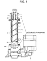
- FIG. 1 shows the structure of an ice making mechanism portion of the auger type ice making machine.
- An auger 3 that has a helical blade 31a arranged in a helical manner on an outer circumference thereof is disposed in an inner portion of a cylindrical cooling cylinder 1.
- the auger 3 is rotatably supported at upper and lower end portions thereof.
- the auger 3 is composed of a main body portion 31 provided with the helical blade 31a, and an upper shaft portion 32 and a lower shaft portion 33 that each have an outer diameter that is smaller than that of the main body portion 31.
- the upper shaft portion 32 is supported by a bearing 4 so as to be freely rotatable.
- the lower shaft portion 33 is also freely rotatably supported, and in addition, there is a spline 33a formed in an end portion of the lower shaft portion 33.
- a geared motor 2 that is provided with a speed reducer and a drive motor is joined to the lower shaft portion 33 through the spline 33a.
- a fixed blade 5 having a compression passage 5a is provided to an upper portion of the cooling cylinder 1.
- a method of manufacturing the auger 3 is explained next based on FIG. 2.
- the upper shaft member 42 and the lower shaft member 43 each use a material that has a smaller diameter than the diameter of the main body member 41.
- One end surface 41a of the main body member 41 and an opposing end surface 42a of the upper shaft member 42 are coaxially joined by friction welding so that their centers coincide with each other. Specifically, the end surface 41a and the end surface 42a are brought into abutment with each other and a pressure is applied thereto.
- One of the members, for example the upper shaft member 42 is then rotated in this state, and joining surfaces are heated by utilizing frictional heat due to relative rotational motion.
- the upper shaft member 42 and the main body member 41 reach a softened state, relative rotation is stopped, and an upset pressure is applied, thus pressure welding the two members together.
- the main body member 41 and the upper shaft member 42 are joined in a stepped state because their diameters differ.
- Burnishing is performed next on a corner portion 35 that includes the outer circumferential edge 34a and a corner portion 37 that includes the outer circumferential edge 36a. That is, roller burnishing is performed at joining locations where joining is performed by friction welding.
- burnishing is performed by pressing a Superoll 50 shown in FIG. 3 and FIG. 4 in arrow direction A toward the corner portions 35 and 37 of the rotating auger 3.
- the Superoll 50 has a roll holder 53 that is connected to a distal end of a body 51 through a head joint 52.
- a roller 55 that is freely rotatable about a roller support shaft center 54 that is perpendicular to the longitudinal direction of the body 51 is provided to the roller holder 53.
- the roller 55 is a disk whose outer circumferential portion 55a is pointed in a tapered shape.
- An outer circumferential end 55b of the distal end that is pointed in a tapered shape is formed having a corner rounding R1.
- a pre-load adjustment knob 56 is provided at a rear end of the body 51 in order to adjust the load that is initially applied when pressing the roller 55 against a work piece. Further, a shank 57 is attached to the body 51. Positioning on the body 51 can thus be performed.
- the Superoll 50 is attached as an NC lathe tool, and the auger 3 is attached as a work piece.
- the auger 3 is rotated, and the outer circumferential end 55b of the roller 55 is first pressed against the corner portion 35.
- the roller 55 rotates about the roller support shaft center 54 while pressing on the surface of the corner portion 35. Pressure is applied to a surface of the corner portion 35 including locations where joining is performed by friction welding.
- the surface of the corner portion 35 plastically deforms, and is finished to a smooth surface.
- the amount that the roller 55 is pressed (burnishing amount) when performing the roller burnishing is from 0.04 to 0.07 mm.
- the auger 3 having a stable strength can be obtained at a relatively low cost.
- the Superoll 50 has a shape in which the outer circumferential end 55b of the roller 55 has a pointed configuration, and the periphery of the roller 55 is recessed with respect to a work piece contact portion of the roller 55. Roller burnishing can therefore be performed easily in the corner portions 35 and 37.
- the strength of the joining portions can be increased by performing roller burnishing on the joining locations where joining is performed by friction welding.
- the joining locations at which roller burnishing is performed are not limited, however, to narrow locations like the corner portions 35 and 37. Further, rollerburnishingmayalsobeperformedonlocations where members having identical diameters are joined together by friction welding.
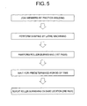
- roller burnishing is performed one time after joining the members by friction welding and performing shaping by lathe machining. In this embodiment, however, as shown in FIG. 5, roller burnishing is performed two times on the same location, with a predetermined interval of time therebetween.
- the time interval be from 1 to 2 months.
- Roller burnishing can increase fatigue strength if performed a plurality of times on the same location. However, when performed too many times, the effect of roller burnishing lessens. Further, if roller burnishing is performed a plurality of times in succession without allowing for a time interval, the fatigue strength increasing effect lessens. It has been found that the fatigue strength can be increased by performing roller burnishing two times on the same location, with a long period of time interval of 1 to 2 months therebetween.
- roller burnishing is performed two times with a time interval therebetween in this embodiment, roller burnishing may also be performed three or more times, with time intervals therebetween, depending upon the type, the size, and the like of the material to be machined.
- Embodiments 1 and 2 Examples of methods of manufacturing an auger of an auger type ice making machine are explained in Embodiments 1 and 2 as described above. However, in addition to manufacturing the auger of the auger type ice making machine, it is also possible to apply the method of manufacturing a rotary shaft according to the present invention to a wide variety of applications where it is required to increase a strength of a joining portion for a member made by joining a plurality of members through friction welding.
Landscapes
- Engineering & Computer Science (AREA)
- Mechanical Engineering (AREA)
- Pressure Welding/Diffusion-Bonding (AREA)
- Shafts, Cranks, Connecting Bars, And Related Bearings (AREA)
Applications Claiming Priority (2)
| Application Number | Priority Date | Filing Date | Title |
|---|---|---|---|
| JP2003335147 | 2003-09-26 | ||
| JP2003335147A JP2005095954A (ja) | 2003-09-26 | 2003-09-26 | 回転軸の製造方法 |
Publications (2)
| Publication Number | Publication Date |
|---|---|
| EP1518632A2 true EP1518632A2 (fr) | 2005-03-30 |
| EP1518632A3 EP1518632A3 (fr) | 2006-03-29 |
Family
ID=34191521
Family Applications (1)
| Application Number | Title | Priority Date | Filing Date |
|---|---|---|---|
| EP04022857A Withdrawn EP1518632A3 (fr) | 2003-09-26 | 2004-09-24 | Procédé de fabrication d'un arbre tournant |
Country Status (3)
| Country | Link |
|---|---|
| US (1) | US20050067465A1 (fr) |
| EP (1) | EP1518632A3 (fr) |
| JP (1) | JP2005095954A (fr) |
Cited By (1)
| Publication number | Priority date | Publication date | Assignee | Title |
|---|---|---|---|---|
| WO2011034670A1 (fr) * | 2009-09-18 | 2011-03-24 | The Boeing Company | Ensemble de soudage par friction-malaxage et procédé associé pour limiter une distorsion dans un joint soudé par friction-malaxage |
Families Citing this family (5)
| Publication number | Priority date | Publication date | Assignee | Title |
|---|---|---|---|---|
| US20060277937A1 (en) * | 2005-06-10 | 2006-12-14 | Manitowoc Foodservice Companies.Inc. | Ice making machine and method of controlling an ice making machine |
| WO2008064563A1 (fr) * | 2006-11-28 | 2008-06-05 | Guangzhou Qiao Li Freezing Technology Co., Ltd | Générateur de glace de type à déchargement continu de glace pour de l'eau de mer/eau douce |
| JP2012002383A (ja) * | 2010-06-14 | 2012-01-05 | Hoshizaki Electric Co Ltd | 製氷機用オーガ |
| WO2014168142A1 (fr) | 2013-04-11 | 2014-10-16 | 株式会社フジコー | Procédé de production d'un cylindre de laminage, cylindre de laminage, et dispositif pour produire un cylindre de laminage |
| KR102856621B1 (ko) * | 2022-10-28 | 2025-09-05 | 김윤수 | 열전도 효율 및 생산성을 향상시킨 오거식 제빙기의 제조방법 |
Citations (1)
| Publication number | Priority date | Publication date | Assignee | Title |
|---|---|---|---|---|
| JPH0835751A (ja) | 1994-05-16 | 1996-02-06 | Hoshizaki Electric Co Ltd | 肉盛り溶接したジャーナル部を有する回転軸の製造方法 |
Family Cites Families (8)
| Publication number | Priority date | Publication date | Assignee | Title |
|---|---|---|---|---|
| US3932061A (en) * | 1972-09-05 | 1976-01-13 | General Motors Corporation | Fluid unit rotor |
| FR2232396A1 (en) * | 1973-06-07 | 1975-01-03 | Kawasaki Heavy Ind Ltd | Friction butt welding of tubes - by revolving ring between butt ends under pressure |
| JPH01241375A (ja) * | 1988-03-24 | 1989-09-26 | Komatsu Ltd | チタン合金の摩擦圧接法 |
| DE4003731A1 (de) * | 1990-02-08 | 1991-08-14 | Teves Gmbh Alfred | Kaltverformter kolben fuer hydraulisch arbeitende bremse |
| US6064030A (en) * | 1994-05-16 | 2000-05-16 | Hoshizaki Denki Kabushiki Kaisha | Manufacturing method of rotary shaft with hard faced journal |
| PT735247E (pt) * | 1995-03-28 | 2000-11-30 | Bleistahl Prod Gmbh & Co Kg | Processo para a montagem e acabamento de uma sede de valvula de metal em po. |
| JP2000343246A (ja) * | 1999-06-03 | 2000-12-12 | Mitsubishi Motors Corp | 軸状部材の摩擦圧接部構造及び摩擦圧接方法 |
| US6473964B1 (en) * | 2000-01-12 | 2002-11-05 | Keystone Investment Corporation | Method of fabricating camshafts |
-
2003
- 2003-09-26 JP JP2003335147A patent/JP2005095954A/ja active Pending
-
2004
- 2004-09-23 US US10/947,244 patent/US20050067465A1/en not_active Abandoned
- 2004-09-24 EP EP04022857A patent/EP1518632A3/fr not_active Withdrawn
Patent Citations (1)
| Publication number | Priority date | Publication date | Assignee | Title |
|---|---|---|---|---|
| JPH0835751A (ja) | 1994-05-16 | 1996-02-06 | Hoshizaki Electric Co Ltd | 肉盛り溶接したジャーナル部を有する回転軸の製造方法 |
Cited By (1)
| Publication number | Priority date | Publication date | Assignee | Title |
|---|---|---|---|---|
| WO2011034670A1 (fr) * | 2009-09-18 | 2011-03-24 | The Boeing Company | Ensemble de soudage par friction-malaxage et procédé associé pour limiter une distorsion dans un joint soudé par friction-malaxage |
Also Published As
| Publication number | Publication date |
|---|---|
| US20050067465A1 (en) | 2005-03-31 |
| EP1518632A3 (fr) | 2006-03-29 |
| JP2005095954A (ja) | 2005-04-14 |
Similar Documents
| Publication | Publication Date | Title |
|---|---|---|
| US20150174696A1 (en) | Aluminum Alloy Propeller Shaft and Friction Welding Process Thereof | |
| JPWO2019102808A1 (ja) | 摩擦圧接方法及び工作機械 | |
| EP1518632A2 (fr) | Procédé de fabrication d'un arbre tournant | |
| JP3261432B2 (ja) | 前処理を含む接合装置及び接合方法 | |
| JP4164680B2 (ja) | トロイダル型無段変速機のディスクの加工方法 | |
| JP3204205B2 (ja) | 等速自在継手の加工治具 | |
| US7468015B2 (en) | Method for manufacturing a variator component of continuously variable transmission, and variator component of continuously variable transmission | |
| JPWO2020137551A1 (ja) | 電動パワーステアリング装置用の直動軸、電動パワーステアリング装置、およびこれらの製造方法 | |
| JPWO2020137552A1 (ja) | ステアリング装置用の直動軸、ステアリング装置、およびこれらの製造方法 | |
| JPWO2020166525A1 (ja) | 直動軸およびその製造方法 | |
| JP4888760B2 (ja) | ねじ軸形成方法及びボールねじ機構のねじ軸 | |
| JP2007029978A (ja) | 転造ダイスおよびこれを用いたボール状部付き軸部品の製造方法 | |
| CN211073430U (zh) | 一种抛物线形关节轴承滚包装配设备 | |
| JP4549549B2 (ja) | ボールねじのねじ軸 | |
| JP4596439B2 (ja) | 管端部加工工具 | |
| JP3671114B2 (ja) | エンジンバルブの摩擦接合方法 | |
| JPH03149139A (ja) | クランクシャフトの加工方法 | |
| KR20250164974A (ko) | 환형 열간전조 제품 환형 기어의 절단 방법 및 장치 | |
| JPH06328273A (ja) | 金属棒ないし線材の接合方法 | |
| JP4313801B2 (ja) | 摩擦攪拌接合用工具 | |
| JP2002239753A (ja) | 異種金属製ワークの摩擦圧接方法 | |
| JPH0539797Y2 (fr) | ||
| JP2000061790A (ja) | ローディングカム装置のカム面の加工方法及び加工装置 | |
| JPH07284872A (ja) | 段付棒材の成形加工方法 | |
| KR100731865B1 (ko) | 차량용 등속 조인트의 아웃보드조인트 제작방법 및 그에 의해 제작된 아웃보드조인트 |
Legal Events
| Date | Code | Title | Description |
|---|---|---|---|
| PUAI | Public reference made under article 153(3) epc to a published international application that has entered the european phase |
Free format text: ORIGINAL CODE: 0009012 |
|
| AK | Designated contracting states |
Kind code of ref document: A2 Designated state(s): AT BE BG CH CY CZ DE DK EE ES FI FR GB GR HU IE IT LI LU MC NL PL PT RO SE SI SK TR |
|
| AX | Request for extension of the european patent |
Extension state: AL HR LT LV MK |
|
| PUAL | Search report despatched |
Free format text: ORIGINAL CODE: 0009013 |
|
| AK | Designated contracting states |
Kind code of ref document: A3 Designated state(s): AT BE BG CH CY CZ DE DK EE ES FI FR GB GR HU IE IT LI LU MC NL PL PT RO SE SI SK TR |
|
| AX | Request for extension of the european patent |
Extension state: AL HR LT LV MK |
|
| AKX | Designation fees paid | ||
| STAA | Information on the status of an ep patent application or granted ep patent |
Free format text: STATUS: THE APPLICATION IS DEEMED TO BE WITHDRAWN |
|
| 18D | Application deemed to be withdrawn |
Effective date: 20060930 |
|
| REG | Reference to a national code |
Ref country code: DE Ref legal event code: 8566 |