EP1518616A2 - Blechwalzmaschine für das Sicken, Bördeln und dergleichen von dünnem Blech - Google Patents
Blechwalzmaschine für das Sicken, Bördeln und dergleichen von dünnem Blech Download PDFInfo
- Publication number
- EP1518616A2 EP1518616A2 EP04405586A EP04405586A EP1518616A2 EP 1518616 A2 EP1518616 A2 EP 1518616A2 EP 04405586 A EP04405586 A EP 04405586A EP 04405586 A EP04405586 A EP 04405586A EP 1518616 A2 EP1518616 A2 EP 1518616A2
- Authority
- EP
- European Patent Office
- Prior art keywords
- machine according
- bead
- lever
- bearing block
- depth
- Prior art date
- Legal status (The legal status is an assumption and is not a legal conclusion. Google has not performed a legal analysis and makes no representation as to the accuracy of the status listed.)
- Granted
Links
- 239000011324 bead Substances 0.000 title claims abstract description 60
- 239000002184 metal Substances 0.000 title claims abstract description 5
- 238000005096 rolling process Methods 0.000 title claims description 22
- 230000008878 coupling Effects 0.000 claims 6
- 238000010168 coupling process Methods 0.000 claims 6
- 238000005859 coupling reaction Methods 0.000 claims 6
- 238000002788 crimping Methods 0.000 claims 1
- 238000005555 metalworking Methods 0.000 claims 1
- 238000003754 machining Methods 0.000 description 14
- 230000005540 biological transmission Effects 0.000 description 6
- 238000003860 storage Methods 0.000 description 4
- 235000013372 meat Nutrition 0.000 description 2
- 210000001520 comb Anatomy 0.000 description 1
- 230000001419 dependent effect Effects 0.000 description 1
- 238000000034 method Methods 0.000 description 1
- 238000003825 pressing Methods 0.000 description 1
- 239000007787 solid Substances 0.000 description 1
Images
Classifications
-
- B—PERFORMING OPERATIONS; TRANSPORTING
- B21—MECHANICAL METAL-WORKING WITHOUT ESSENTIALLY REMOVING MATERIAL; PUNCHING METAL
- B21D—WORKING OR PROCESSING OF SHEET METAL OR METAL TUBES, RODS OR PROFILES WITHOUT ESSENTIALLY REMOVING MATERIAL; PUNCHING METAL
- B21D17/00—Forming single grooves in sheet metal or tubular or hollow articles
- B21D17/04—Forming single grooves in sheet metal or tubular or hollow articles by rolling
-
- B—PERFORMING OPERATIONS; TRANSPORTING
- B21—MECHANICAL METAL-WORKING WITHOUT ESSENTIALLY REMOVING MATERIAL; PUNCHING METAL
- B21D—WORKING OR PROCESSING OF SHEET METAL OR METAL TUBES, RODS OR PROFILES WITHOUT ESSENTIALLY REMOVING MATERIAL; PUNCHING METAL
- B21D19/00—Flanging or other edge treatment, e.g. of tubes
- B21D19/02—Flanging or other edge treatment, e.g. of tubes by continuously-acting tools moving along the edge
- B21D19/04—Flanging or other edge treatment, e.g. of tubes by continuously-acting tools moving along the edge shaped as rollers
- B21D19/043—Flanging or other edge treatment, e.g. of tubes by continuously-acting tools moving along the edge shaped as rollers for flanging edges of plates
Definitions
- the invention relates to a plate rolling machine for beading, Beading and the like of thin sheets, with a Machine frame and mounted on a working head and motor driven work rolls, which over Adjusting means for the bead depth are mutually adjustable, a work roll on a fixed storage block and a other work role stored on a pivotable bearing block are and with drive means for introducing the bead depth.
- a sheet rolling machine of the type mentioned is in the prior art from EP 0 585 613 A of the applicant. These has work rolls, which are paired with adjusting means are stored a roller stand. A work role is in one pivoted yoke stored. At this yoke is a tension rod 13th attached to which a pressure piston cylinder attacks. This Pressure piston cylinder is also supported on the fixed bearing block and serves as a drive means for introducing the bead depth. Of the Tension rod also has a stop on which an eccentric a Adjusting lever is applied. With this adjustment lever or eccentric the bead depth can be adjusted.
- the invention is based on the object, a sheet rolling machine to create the aforementioned type, the more cost-effectively and also easier to use.
- the task is in a generic sheet rolling machine thereby solved that the drive means for adjusting the bead depth having a pivotable lever which is fixed to a frame Fulcrum is mounted and the pivoting bearing block cooperates for introducing the bead depth.
- the introduction takes place the depth of the bead by means of a pivoting lever, the having a frame-fixed pivot point.
- This lever engages the pivotable bearing block.
- Such a lever allows one simpler and more cost-effective design of the sheet rolling machine. In particular, this can be a much easier one Plate rolling machine realized with a multi-part working head become.
- a working head has three parts on, in each case a tool, in particular a Work roller pair is arranged.
- the setting of the bead depth is then particularly easy if said lever cooperates with a winch which forms a stop which determines the depth of the bead.
- a winch which forms a stop which determines the depth of the bead.
- the hand crank can, however, also by a remotely actuable stop to be replaced with the aforementioned Lever works together.
- the said lever is according to a development of the invention a two-armed lever, with one arm on the pivoting bearing block abuts and on the other arm an air cylinder or a engages other suitable drive element.
- a central compressed air supply is, which with the said drive means for introducing the Sickle depth is connectable.
- the compressed air supply provided with connecting means, which are engageable and disengageable.
- This can in particular a Plate rolling machine realized with a multi-part working head in each case the required part of the machining head can be supplied with compressed air.
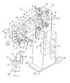
- the sheet rolling machine 1 shown in FIG. 1 has a machine frame 37, with a base plate 38 on a building floor is set and with wheels 28 for adjusting the sheet rolling machine 1 is provided.
- a machining head 2 is arranged, as shown protrudes radially and a lower and fixed bearing block 8 with a lower bead roll 23 and an upper one pivotable bearing block 7 with an upper bead roll 24 has.
- the two bead rolls 23 and 24 are above a lower Beading shaft 10 and upper bead shaft 9 connected to a drive 3, the one upwardly projecting drive shaft 4 and a Gear unit 29 has.
- the drive shaft 4 is in particular powered by a motor.
- the transmission unit 29 has a Bevel gear pair 5, with which the lower bead shaft 10 driven is. About a Stirnradpar 6, the rotational movement of the lower Bead shaft 10 transmitted to the upper bead shaft 9.
- the both bead waves 9 and 10 are parallel to each other and the directions of rotation and the rotational speeds are the same.
- the direction of rotation can be changed according to double arrow B.
- the upper bearing block 7 is limited about a horizontal axis of rotation 20 pivotable. This axis of rotation 20 is as can be seen on rear end of the upper bearing block 7 is arranged.
- the storage block 7 can also by means of a pivot lever 19 and one here not shown eccentric in the directions of the double arrow X. be limited horizontally.
- the comparatively small one Adjustment range is for example 2 mm. By means of a Clamping lever 21, this adjustment can be fixed.
- This horizontal Adjustment of the upper bearing block 7 is by the Helical pair 6 allows that within the adjustment combs.
- the dimension b indicates the distance from the inside of the upper bead 24 to the guide surface of the stop plate 25 at.
- a Clamping lever 17 By means of a Clamping lever 17, a set dimension b can be fixed.
- the Stop plate 25 serves to guide a sheet to be machined 26. For processing, the sheet 26 in the directions of Double arrow Z passed between the bead rollers 23 and 24 and thereby the bead S shown in Figure 3 incorporated.
- a Drive A arranged, which has an air pressure cylinder 14, which via a switch, not shown here, for example can be operated via an electric foot switch.
- a Piston rod 39 of the air cylinder 14 is at a rear hinged forked end of a lever 11. Will the air cylinder 14 actuated at the said switch, so the drives Piston rod 39 upwards until a mounted on the lever 11 rotary member 41 is present at a hand crank 13.
- the hand crank 13 limited thus the possible pivotal movement of the lever 11 and forms with it a stop. If the lever 11 is pivoted as mentioned, so moves a nose 11a of the lever 11 down and pivots according to the upper bearing block 7 to the Rotation axis 20.
- the upper bead roll 24 in Direction of the double arrow Y against the retroactive force of a Spring element 15 vertically downwards against the lower bead 23 moves.
- the Hand crank 13 turned clockwise.
- the mother 22 preferably has a left hand thread, thereby the hand crank 13 moves up.
- the compressed air cylinder 14 can thus the lever 11 is pivoted again by a certain amount so that the nose 11a continues to follow the upper bearing block 7 moved down.
- the bead depth can thus by appropriate incrementally turning the hand crank 13 in a clockwise direction until finally the intended depths and so that the bead S is reached.
- the hand crank 13 is moved down.
- the bead depth is thus reduced accordingly.
- the Position of the hand crank 13 can by a not shown here Scale or other appropriate means.
- the winch 13 thus forms a stop. It can also be done by others suitable means are replaced, although also conceivable means are that allow a remote control. For example the hand crank 13 is rotated by an electric motor become.
- the air cylinder 14 thus forms the drive with the lever 11 A for introducing the bead depth.
- the air cylinder 14 could also be replaced by other suitable drive means become.
- a compressed air line 42, which to the compressed air cylinder 14 leads, is merely indicated in FIG.
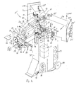
- the sheet rolling machine 1 'shown in FIG. 4 operates essentially same as the above-discussed sheet rolling machine 1.
- a Machine frame 37 ' is formed here but solid and has at least one extendable wheel 30, which together with the wheels 28 a method of the sheet rolling machine 1 'allows.
- the two corrugation shafts shown at the processing head 2a 9 and 10, the lever 11, the air cylinder 14 and the Lever 19 and other parts explained above are thus also provided at the machining head 2b and the machining head 2c.
- the processing heads 2b and 2c also have accordingly above outstanding each a hand crank 13 and 13 'on, with each of which the stop for a corresponding lever 11th is adjustable.
- the turntable 40 is about a vertical axis 43 rotatable, which runs in the drive shaft 4.
- the sheet rolling machine 1 ' is provided for a fixed working position, to each of the desired processing head 2a, 2b or 2c is brought.
- the arranged at the processing head 2b Bead rolls 23 'and 24' are usually different from the Bead rolls 23 and 24 and this also applies to the not shown here Bead rolls of the working head 2c.
- These bead rolls can be replaced, including in the machine frame 37 ' a tool box 27 is provided.
- the working position provided at the processing head 2b and are for editing of the sheet 26 the bead rollers 23 and 24 needed, so is the Turntable 40 counterclockwise rotated by 120 °, so now the machining head 2a is in the earlier position of the machining head 2b is located. With a rotation of 120 ° clockwise For example, the machining head 2c can be pivoted into the working position become.
- the bevel gear pair 5 are decoupled.
- a compressed air cylinder 35 provided with a wedge 36 horizontally displaceable and thus the bevel gear 5 connected to the shaft 4 are lowered can until it is attached to the attached to the bottom bead shaft 10 Bevel gear is no longer engaged.
- the wedge 36 in the opposite direction moved, so moves the sliding on the shaft 4 stored bevel gear 5 upwards and comes into engagement with the other bevel gear.
- the pivot bearing for the turntable 40 is indicated in Figure 4 by the reference numeral 34.
- Such Swivel bearing for the axial and radial guidance of the turntable 40 may be formed in a conventional manner.
- the compressed air line to the turntable 40 is also the compressed air line to the turntable 40 and thus to the compressed air cylinder 35 and the corresponding compressed air cylinder 14 interrupted.
- the air cylinder 33 can via a line not shown here with the foot switch 31 are operated.
- the index pin moves 32 in the directions of the double arrow W upwards or downwards below. If the index pin 32 is driven down, the Compressed air connection to the turntable 40 interrupted and this can after decoupling the gear unit 29 free in both Directions are turned.
- the air cylinder 14 of the two processing heads 2a and 2c are not supplied with compressed air, so at a corresponding actuation only at the two bead rolls 23 'and 24' the corresponding Sickle depth can be introduced. This is also for safety reasons advantageous because the unneeded seepage rollers not turn.
- the transmission unit 29 is disengaged and the index pin 32 is in a lower position.
- the Turntable 40 is now rotated until the desired machining head 2a, 2b and 2c in the desired working position.
- the machining head 2b after a corresponding rotation of the turntable 40 in the working position, so is by pressing the foot switch 31 of the index pin 32 moved up. This will be the Compressed air cylinder 35 and the air cylinder 14 of the machining head 2b supplied with air pressure.
- the transmission unit 29 can be coupled with it and by pivoting the upper bead 24 'the set bead depth are introduced. By turning the hand crank 13 ', the bead depth is set or adjusted until the desired depth of sill is reached.
- the to be machined plate 26 is between the driven bead rollers passed through, wherein the sheet 26 on the stop plate 25 'is guided.
- the stopper plate 25 ' and the lower bearing block 8 adjusted.
- Becomes another machining head For example, the processing head 2a or 2c needed so the gear unit 29 is decoupled and the index pin 32 drove down.
- the turntable 40 can now freely around the vertical axis 43 are rotated until the desired machining head is in the working position.
- After setting the Sick depth on the hand crank 13 or 13 "and corresponding Positioning of the stop plate 25 or 25 "and an adjustment of the upper bearing block 7 in a direction of the arrow X by pivoting the lever 19 is the index pin 32nd moved up and the transmission unit 29 coupled.
Landscapes
- Engineering & Computer Science (AREA)
- Mechanical Engineering (AREA)
- Tyre Moulding (AREA)
- Milling Processes (AREA)
- Manufacture Of Metal Powder And Suspensions Thereof (AREA)
- Shaping Metal By Deep-Drawing, Or The Like (AREA)
Abstract
Description
- Figur 1
- schematisch eine teilweise geschnittene Ansicht einer erfindungsgemässen Blechwalzmaschine,
- Figur 2
- ein Teilquerschnitt durch die Sickenrollen,
- Figur 3
- ein Teilquerschnitt durch ein bearbeitetes Blech und
- Figur 4
- schematisch eine räumliche Ansicht einer erfindungsgemässen Blechwalzmaschine nach einer Variante.
- 1
- Blechwalzmaschine
- 2
- Bearbeitungskopf (2a,2b, 2c)
- 3
- Antrieb (Motor-Getriebeeinheit
- 4
- Antriebswelle
- 5
- Kegelradpaar
- 6
- Stirnradpaar
- 7
- Oberer Lagerblock
- 7a
- Oberseite
- 8
- Unterer Lagerblock 9 Obere Sickenwelle
- 9
- Obere Sickenwelle
- 10
- Untere Sickenwelle
- 11
- Hebel
- 11a
- Nase
- 12
- Drehpunkt
- 13
- Handkurbel
- 14
- Druckluftzylinder
- 15
- Federelement
- 16
- Verstellgriff
- 17
- Klemmhebel
- 18
- Führungsstange
- 19
- Schwenkhebel
- 20
- Drehachse
- 21
- Klemmhebel
- 22
- Mutter
- 23
- Untere Sickenrolle
- 24
- Obere Sickenrolle
- 25
- Anschlagplatte
- 26
- Blech
- 27
- Werkzeugkasten
- 28
- Räder
- 29
- Getriebeeinheit
- 30
- Ausfahrbares Rad
- 31
- Fussschalter für Index-bolzen 32
- 32
- Indexbolzen mit Druckluftdurchführung zum Druckluftzylinder 14
- 33
- Druckluftzylinder
- 34
- Drehlager
- 35
- Druckluftzylinder
- 36
- Keil
- 37
- Maschinengestell
- 38
- Grundplatte
- 39
- Kolbenstange
- 40
- Drehtisch
- 41
- Teil
- 42
- Druckluftleitung
- 43
- Achse
- A
- Antriebsmittel
- B
- Doppelpfeil
- X
- Doppelpfeil
- Y
- Doppelpfeil
- Z
- Doppelpfeil
- b
- Sickenfleisch
Claims (16)
- Blechwalzmaschine für das Sicken, Bördeln und dergleichen von dünnen Blechen (26), mit einem Maschinengestell (37, 37'), und mit an wenigstens einem Arbeitskopf (2, 2a, 2b, 2c) gelagerten und motorisch angetriebenen Arbeitsrollen (23, 24; 23', 24'), welche über Einstellmittel (11, 13, 14) für die Sickentiefe zueinander verstellbar sind, wobei eine Arbeitsrolle (23, 23') an einem festen Lagerblock (8) und eine andere Arbeitsrolle (24, 24') an einem verschwenkbaren Lagerblock (7) gelagert ist und mit Antriebsmitteln (A) zum Einbringen der Sickentiefe, dadurch gekennzeichnet, dass die Antriebsmittel (A) einen schwenkbaren Hebel (11) aufweisen, der mit dem verschwenkbaren Lagerblock (7) zum Einbringen der Sickentiefe zusammenarbeitet.
- Maschine nach Anspruch 1, dadurch gekennzeichnet, dass der genannte Hebel (11) zweiarmig ausgebildet ist und mit einem ersten Arm (11b) am schwenkbaren Lagerblock (7) anliegt und mit dem zweiten Arm (11c) mit einem Antriebsorgan (14) verbunden ist.
- Maschine nach Anspruch 1 oder 2, dadurch gekennzeichnet, dass der genannte Hebel (11) über dem schwenkbaren Lagerblock (7) an einem Gestell 37 schwenkbar gelagert ist.
- Maschine nach einem der Ansprüche 1 bis 3, dadurch gekennzeichnet, dass der Hebel (11) von einem vorderen Ende eine Nase (11a) aufweist, die lose an einer Oberseite (7a) des schwenkbaren Lagerblocks (7) anliegt.
- Maschine nach einem der Ansprüche 1 bis 4, dadurch gekennzeichnet, dass der schwenkbare Lagerblock (7) mittels eines Federelementes (15) am genannten Hebel (11) angepresst wird.
- Maschine nach Anspruch 5, dadurch gekennzeichnet, dass das Federelement (15) zwischen den beiden Lagerblöcken (7, 8) angeordnet und an diesen abgestützt ist.
- Maschine nach einem der Ansprüche bis 6, dadurch gekennzeichnet, dass die Schwenkbarkeit des genannten Hebels (11) zur Einstellung der Sickentiefe durch Anschlagmittel (13) begrenzt ist.
- Maschine nach Anspruch 7, dadurch gekennzeichnet, dass die genannten Anschlagmittel (13) eine Handkurbel aufweisen, die in einer Mutter (22) gelagert ist.
- Maschine nach Anspruch einem der Ansprüche 1 bis 8, dadurch gekennzeichnet, dass auf dem Maschinengestell (37') ein Drehtisch (40) gelagert, der wenigstens zwei Arbeitsköpfe (2a, 2b, 2c), vorzugsweise drei Arbeitsköpfe aufweist.
- Maschine nach Anspruch 9, dadurch gekennzeichnet, dass Kupplungsmittel (32, 33) vorgesehen sind, mit denen eine Druckluftleitung mit dem Drehtisch (40) kuppelbar ist.
- Maschine nach Anspruch 9 oder 10, dadurch gekennzeichnet, dass die Kupplungsmittel (32, 33) einen fern bedienbaren Antrieb (33) aufweisen.
- Maschine nach Anspruch 10 oder 11, dadurch gekennzeichnet, dass die Kupplungsmittel (32, 33) einen verstellbaren Indexbolzen (32) aufweisen.
- Maschine nach Anspruch einem der Ansprüche 10 bis 12, dadurch gekennzeichnet, dass wenigstens zwei Sickenwellen (9, 10) über eine Getriebeeinheit (29) angetrieben ist, die über ein Antriebsmittel (35) vorzugsweise fernbedienbar kuppelbar ist.
- Blechbearbeitungsmaschine für das Sicken, Bördeln und dergleichen von Blechen (26), mit einem Maschinengestell (37, 37'), und mit an wenigstens einem Arbeitskopf (2, 2a, 2b, 2c) gelagerten und angetriebenen Arbeitsrollen (23, 24; 23', 24'), welche über Einstellmittel (11, 13, 14) für die Sickentiefe zueinander verstellbar sind und mit Antriebsmitteln (A) zum Einbringen der Sickentiefe, dadurch gekennzeichnet, dass an einem Drehtisch (40) wenigstens zwei Arbeitsköpfe (2, 2a, 2b, 2c) angeordnet sind und dass Kupplungsmittel (32, 33) vorgesehen sind, mit denen eine Druckluftleitung in wenigstens zwei Drehpositionen mit dem Drehtisch (40) kuppelbar ist.
- Maschine nach Anspruch 14, dadurch gekennzeichnet, dass die Kupplungsmittel (32, 33) fernbedienbar sind.
- Maschine nach Anspruch 14 oder 15, dadurch gekennzeichnet, dass die Kupplungsmittel (32, 33) wenigstens einen verstellbaren Indexbolzen (32) aufweisen.
Priority Applications (1)
| Application Number | Priority Date | Filing Date | Title |
|---|---|---|---|
| EP06015880A EP1724033B1 (de) | 2003-09-25 | 2004-09-17 | Blechbearbeitungsmachine für das Sicken, Bördeln und dergleichen von dünnem Blech |
Applications Claiming Priority (2)
| Application Number | Priority Date | Filing Date | Title |
|---|---|---|---|
| CH16322003 | 2003-09-25 | ||
| CH16322003 | 2003-09-25 |
Related Child Applications (2)
| Application Number | Title | Priority Date | Filing Date |
|---|---|---|---|
| EP06015880A Division EP1724033B1 (de) | 2003-09-25 | 2004-09-17 | Blechbearbeitungsmachine für das Sicken, Bördeln und dergleichen von dünnem Blech |
| EP06015880.5 Division-Into | 2006-07-31 |
Publications (4)
| Publication Number | Publication Date |
|---|---|
| EP1518616A2 true EP1518616A2 (de) | 2005-03-30 |
| EP1518616A3 EP1518616A3 (de) | 2005-04-20 |
| EP1518616B1 EP1518616B1 (de) | 2008-04-16 |
| EP1518616B2 EP1518616B2 (de) | 2012-03-07 |
Family
ID=34140509
Family Applications (2)
| Application Number | Title | Priority Date | Filing Date |
|---|---|---|---|
| EP04405586A Expired - Lifetime EP1518616B2 (de) | 2003-09-25 | 2004-09-17 | Blechwalzmaschine für das Sicken, Bördeln und dergleichen von dünnem Blech |
| EP06015880A Expired - Lifetime EP1724033B1 (de) | 2003-09-25 | 2004-09-17 | Blechbearbeitungsmachine für das Sicken, Bördeln und dergleichen von dünnem Blech |
Family Applications After (1)
| Application Number | Title | Priority Date | Filing Date |
|---|---|---|---|
| EP06015880A Expired - Lifetime EP1724033B1 (de) | 2003-09-25 | 2004-09-17 | Blechbearbeitungsmachine für das Sicken, Bördeln und dergleichen von dünnem Blech |
Country Status (3)
| Country | Link |
|---|---|
| EP (2) | EP1518616B2 (de) |
| DE (2) | DE502004006626D1 (de) |
| ES (1) | ES2303934T5 (de) |
Cited By (6)
| Publication number | Priority date | Publication date | Assignee | Title |
|---|---|---|---|---|
| WO2008145396A1 (de) * | 2007-06-01 | 2008-12-04 | Edag Gmbh & Co. Kgaa | Rollbördelwerkzeug |
| US9079236B2 (en) | 2011-06-01 | 2015-07-14 | Jonas Wallinder | Bead roller |
| CN105170748A (zh) * | 2015-10-14 | 2015-12-23 | 张家港保税区亚鑫精密制管有限公司 | 一种用于滚槽机上的滚轮装置 |
| CN110252864A (zh) * | 2019-07-02 | 2019-09-20 | 杨圣斌 | 翻边轴翻转机构及具有该机构的管状法兰成型设备 |
| US10449586B2 (en) | 2014-05-02 | 2019-10-22 | Interver Management S.A. | Method and device for manufacturing a tubular lagging element from sheet metal |
| CN110883158A (zh) * | 2019-12-24 | 2020-03-17 | 苏州苏宏模具有限公司 | 一种冲压件卷边结构 |
Families Citing this family (2)
| Publication number | Priority date | Publication date | Assignee | Title |
|---|---|---|---|---|
| DE102015119589B4 (de) * | 2014-11-14 | 2023-07-20 | Ferrobotics Compliant Robot Technology Gmbh | Vorrichtung und Verfahren zum robotergestützen Rollfalzen |
| CN112692133B (zh) * | 2021-03-25 | 2021-07-02 | 烟台大学文经学院 | 一种自动化管道压槽生产线 |
Family Cites Families (8)
| Publication number | Priority date | Publication date | Assignee | Title |
|---|---|---|---|---|
| DE1221599B (de) * | 1956-10-15 | 1966-07-28 | Victaulic Co Of America | Verfahren zum Sicken von ringfoermigen Kupplungsnuten in die Waende duennwandiger Rohre und Vorrichtung zu seiner Ausuebung |
| DE843536C (de) * | 1950-08-29 | 1952-07-10 | Theo Dr-Ing Krueckels | Sickenmaschine |
| US5079940A (en) * | 1990-06-28 | 1992-01-14 | Emerson Electric Co. | Roll grooving apparatus |
| CH686662A5 (de) * | 1992-09-02 | 1996-05-31 | Mabi Isoliermaschinen | Blechbearbeitungsmaschine. |
| US5528919A (en) * | 1995-02-02 | 1996-06-25 | Emerson Electric Company | Roll grooving apparatus |
| DE10013801A1 (de) † | 2000-03-20 | 2001-10-18 | Reinhardt Gmbh Maschbau | Blechumformmaschine |
| ATE328681T1 (de) * | 2000-12-04 | 2006-06-15 | Mabi Ag | Sickenmaschine |
| US6591652B1 (en) * | 2001-07-13 | 2003-07-15 | Emerson Electric Co. | Roll grooving apparatus |
-
2004
- 2004-09-17 DE DE200450006626 patent/DE502004006626D1/de not_active Expired - Lifetime
- 2004-09-17 EP EP04405586A patent/EP1518616B2/de not_active Expired - Lifetime
- 2004-09-17 ES ES04405586T patent/ES2303934T5/es not_active Expired - Lifetime
- 2004-09-17 EP EP06015880A patent/EP1724033B1/de not_active Expired - Lifetime
- 2004-09-17 DE DE200450006827 patent/DE502004006827D1/de not_active Expired - Lifetime
Non-Patent Citations (1)
| Title |
|---|
| None |
Cited By (10)
| Publication number | Priority date | Publication date | Assignee | Title |
|---|---|---|---|---|
| WO2008145396A1 (de) * | 2007-06-01 | 2008-12-04 | Edag Gmbh & Co. Kgaa | Rollbördelwerkzeug |
| CN101687245B (zh) * | 2007-06-01 | 2012-07-18 | Fftedag生产有限公司 | 滚压卷边工具 |
| US8408036B2 (en) | 2007-06-01 | 2013-04-02 | Fft Edag Produktionssysteme Gmbh & Co. Kg | Edge curling tool |
| US9079236B2 (en) | 2011-06-01 | 2015-07-14 | Jonas Wallinder | Bead roller |
| US10449586B2 (en) | 2014-05-02 | 2019-10-22 | Interver Management S.A. | Method and device for manufacturing a tubular lagging element from sheet metal |
| CN105170748A (zh) * | 2015-10-14 | 2015-12-23 | 张家港保税区亚鑫精密制管有限公司 | 一种用于滚槽机上的滚轮装置 |
| CN105170748B (zh) * | 2015-10-14 | 2017-04-12 | 张家港保税区亚鑫精密制管有限公司 | 一种用于滚槽机上的滚轮装置 |
| CN110252864A (zh) * | 2019-07-02 | 2019-09-20 | 杨圣斌 | 翻边轴翻转机构及具有该机构的管状法兰成型设备 |
| CN110252864B (zh) * | 2019-07-02 | 2024-05-28 | 杨圣斌 | 翻边轴翻转机构及具有该机构的管状法兰成型设备 |
| CN110883158A (zh) * | 2019-12-24 | 2020-03-17 | 苏州苏宏模具有限公司 | 一种冲压件卷边结构 |
Also Published As
| Publication number | Publication date |
|---|---|
| DE502004006827D1 (de) | 2008-05-29 |
| EP1724033B1 (de) | 2008-03-19 |
| EP1724033A2 (de) | 2006-11-22 |
| EP1518616A3 (de) | 2005-04-20 |
| EP1518616B2 (de) | 2012-03-07 |
| EP1518616B1 (de) | 2008-04-16 |
| ES2303934T5 (es) | 2012-05-31 |
| EP1724033A3 (de) | 2006-11-29 |
| DE502004006626D1 (de) | 2008-04-30 |
| ES2303934T3 (es) | 2008-09-01 |
Similar Documents
| Publication | Publication Date | Title |
|---|---|---|
| EP1167626B1 (de) | Baumaschine zum Bearbeiten von Bodenflächen | |
| EP2632620B1 (de) | Vorrichtung zur bildung einer fase | |
| EP1827755B1 (de) | Vorrichtung zum schleifen von harten oberflächen, insbesondere von glasflächen | |
| DE3144022A1 (de) | Spannfutter fuer die vorschubeinrichtung einer rohrreinigungsmaschine | |
| EP2366482B1 (de) | Mehrachsiger Vorritzer | |
| DE19611661A1 (de) | Vorrichtung zum Formen von Draht, insbesondere Universal-Federwindemaschine, mit Schneideinrichtung | |
| EP1909982B1 (de) | Vorrichtung zur anstellung einer bürste an eine rolle | |
| EP0287848A1 (de) | Längsteil-Streifenschere | |
| EP1518616B1 (de) | Blechwalzmaschine für das Sicken, Bördeln und dergleichen von dünnem Blech | |
| DE3016047C2 (de) | ||
| EP1178864B1 (de) | Blechumformmaschine | |
| EP1400629B1 (de) | Schleifmaschine für Schienen, insbesondere für Containerkranschienen | |
| EP0792791B1 (de) | Flurförderzeug mit einer höhenverstellbaren Stand- und/oder Sitzplattform | |
| EP2143516B1 (de) | Sägeaggregat für vertikale Plattensäge | |
| DE1912093C3 (de) | Als Schneidvorrichtung ausgebildete Arbeitseinheit zum Anbringen an einer Walzenschleifmaschine | |
| DE102009024523A1 (de) | Bandsägemaschine mit einem Sägerahmen mit Sägeband | |
| EP0261658A1 (de) | Parkettschleifmaschine | |
| DE2714427C3 (de) | Falzschließmaschine | |
| DE1286379B (de) | Brammen-Fraesmaschine | |
| DE19913087C2 (de) | Antriebseinrichtung zum Einstellen der Winkellage verschwenkbarer Messer eines Scherschnittwerkzeuges zur Herstellung einer Platine | |
| EP0128408A2 (de) | Steinplatten-Bearbeitungsmaschine zum Herstellen innerer und äusserer Konturen der Ränder von Steinplatten | |
| DE2334436A1 (de) | Vier-walzen-blechbiegemaschine | |
| DE19921349C2 (de) | Verfahren und Vorrichtung zur Steuerung eines motorischen Vorschubantriebes | |
| DE3811953A1 (de) | Laengsteil-streifenschere | |
| WO1998003304A1 (de) | Vorrichtung zum schleifen einer zylinderoberfläche, insbesondere einer walze einer papiermaschine |
Legal Events
| Date | Code | Title | Description |
|---|---|---|---|
| PUAI | Public reference made under article 153(3) epc to a published international application that has entered the european phase |
Free format text: ORIGINAL CODE: 0009012 |
|
| PUAL | Search report despatched |
Free format text: ORIGINAL CODE: 0009013 |
|
| AK | Designated contracting states |
Kind code of ref document: A2 Designated state(s): AT BE BG CH CY CZ DE DK EE ES FI FR GB GR HU IE IT LI LU MC NL PL PT RO SE SI SK TR |
|
| AX | Request for extension of the european patent |
Extension state: AL HR LT LV MK |
|
| RIC1 | Information provided on ipc code assigned before grant |
Ipc: 7B 21D 17/04 A Ipc: 7B 21D 19/04 B |
|
| AK | Designated contracting states |
Kind code of ref document: A3 Designated state(s): AT BE BG CH CY CZ DE DK EE ES FI FR GB GR HU IE IT LI LU MC NL PL PT RO SE SI SK TR |
|
| AX | Request for extension of the european patent |
Extension state: AL HR LT LV MK |
|
| 17P | Request for examination filed |
Effective date: 20050531 |
|
| AKX | Designation fees paid |
Designated state(s): DE ES FR IT |
|
| 17Q | First examination report despatched |
Effective date: 20060704 |
|
| 17Q | First examination report despatched |
Effective date: 20060704 |
|
| GRAP | Despatch of communication of intention to grant a patent |
Free format text: ORIGINAL CODE: EPIDOSNIGR1 |
|
| GRAS | Grant fee paid |
Free format text: ORIGINAL CODE: EPIDOSNIGR3 |
|
| GRAA | (expected) grant |
Free format text: ORIGINAL CODE: 0009210 |
|
| AK | Designated contracting states |
Kind code of ref document: B1 Designated state(s): DE ES FR IT |
|
| REF | Corresponds to: |
Ref document number: 502004006827 Country of ref document: DE Date of ref document: 20080529 Kind code of ref document: P |
|
| REG | Reference to a national code |
Ref country code: ES Ref legal event code: FG2A Ref document number: 2303934 Country of ref document: ES Kind code of ref document: T3 |
|
| PLBI | Opposition filed |
Free format text: ORIGINAL CODE: 0009260 |
|
| ET | Fr: translation filed | ||
| PLAX | Notice of opposition and request to file observation + time limit sent |
Free format text: ORIGINAL CODE: EPIDOSNOBS2 |
|
| 26 | Opposition filed |
Opponent name: RAS REINHARDT MASCHINENBAU GMBH Effective date: 20090116 |
|
| PLAF | Information modified related to communication of a notice of opposition and request to file observations + time limit |
Free format text: ORIGINAL CODE: EPIDOSCOBS2 |
|
| PLBB | Reply of patent proprietor to notice(s) of opposition received |
Free format text: ORIGINAL CODE: EPIDOSNOBS3 |
|
| PUAH | Patent maintained in amended form |
Free format text: ORIGINAL CODE: 0009272 |
|
| STAA | Information on the status of an ep patent application or granted ep patent |
Free format text: STATUS: PATENT MAINTAINED AS AMENDED |
|
| 27A | Patent maintained in amended form |
Effective date: 20120307 |
|
| AK | Designated contracting states |
Kind code of ref document: B2 Designated state(s): DE ES FR IT |
|
| REG | Reference to a national code |
Ref country code: DE Ref legal event code: R102 Ref document number: 502004006827 Country of ref document: DE Effective date: 20120307 |
|
| REG | Reference to a national code |
Ref country code: ES Ref legal event code: DC2A Ref document number: 2303934 Country of ref document: ES Kind code of ref document: T5 Effective date: 20120531 |
|
| REG | Reference to a national code |
Ref country code: FR Ref legal event code: PLFP Year of fee payment: 13 |
|
| REG | Reference to a national code |
Ref country code: FR Ref legal event code: PLFP Year of fee payment: 14 |
|
| REG | Reference to a national code |
Ref country code: FR Ref legal event code: PLFP Year of fee payment: 15 |
|
| PGFP | Annual fee paid to national office [announced via postgrant information from national office to epo] |
Ref country code: DE Payment date: 20220920 Year of fee payment: 19 |
|
| PGFP | Annual fee paid to national office [announced via postgrant information from national office to epo] |
Ref country code: FR Payment date: 20220922 Year of fee payment: 19 |
|
| PGFP | Annual fee paid to national office [announced via postgrant information from national office to epo] |
Ref country code: IT Payment date: 20220921 Year of fee payment: 19 Ref country code: ES Payment date: 20221121 Year of fee payment: 19 |
|
| REG | Reference to a national code |
Ref country code: DE Ref legal event code: R119 Ref document number: 502004006827 Country of ref document: DE |
|
| PG25 | Lapsed in a contracting state [announced via postgrant information from national office to epo] |
Ref country code: FR Free format text: LAPSE BECAUSE OF NON-PAYMENT OF DUE FEES Effective date: 20230930 Ref country code: DE Free format text: LAPSE BECAUSE OF NON-PAYMENT OF DUE FEES Effective date: 20240403 |
|
| REG | Reference to a national code |
Ref country code: ES Ref legal event code: FD2A Effective date: 20241104 |
|
| PG25 | Lapsed in a contracting state [announced via postgrant information from national office to epo] |
Ref country code: IT Free format text: LAPSE BECAUSE OF NON-PAYMENT OF DUE FEES Effective date: 20230917 |
|
| PG25 | Lapsed in a contracting state [announced via postgrant information from national office to epo] |
Ref country code: IT Free format text: LAPSE BECAUSE OF NON-PAYMENT OF DUE FEES Effective date: 20230917 |
|
| PG25 | Lapsed in a contracting state [announced via postgrant information from national office to epo] |
Ref country code: ES Free format text: LAPSE BECAUSE OF NON-PAYMENT OF DUE FEES Effective date: 20230918 |
|
| PG25 | Lapsed in a contracting state [announced via postgrant information from national office to epo] |
Ref country code: ES Free format text: LAPSE BECAUSE OF NON-PAYMENT OF DUE FEES Effective date: 20230918 |