EP1518486A1 - Schützvorrichtung der Schlitze in einer Trennwand tweier kompartimenten - Google Patents
Schützvorrichtung der Schlitze in einer Trennwand tweier kompartimenten Download PDFInfo
- Publication number
- EP1518486A1 EP1518486A1 EP03292381A EP03292381A EP1518486A1 EP 1518486 A1 EP1518486 A1 EP 1518486A1 EP 03292381 A EP03292381 A EP 03292381A EP 03292381 A EP03292381 A EP 03292381A EP 1518486 A1 EP1518486 A1 EP 1518486A1
- Authority
- EP
- European Patent Office
- Prior art keywords
- guillotine
- slot
- wall
- orifice
- stud
- Prior art date
- Legal status (The legal status is an assumption and is not a legal conclusion. Google has not performed a legal analysis and makes no representation as to the accuracy of the status listed.)
- Granted
Links
- 230000000903 blocking effect Effects 0.000 title abstract 2
- 235000012054 meals Nutrition 0.000 claims abstract description 8
- 238000003860 storage Methods 0.000 claims abstract description 8
- 238000009826 distribution Methods 0.000 claims abstract description 6
- 238000007789 sealing Methods 0.000 claims description 13
- 235000013305 food Nutrition 0.000 claims description 9
- 230000005484 gravity Effects 0.000 claims description 6
- 230000000694 effects Effects 0.000 claims description 4
- 238000000926 separation method Methods 0.000 claims description 4
- 229920003023 plastic Polymers 0.000 claims description 3
- 239000004033 plastic Substances 0.000 claims description 3
- 230000008878 coupling Effects 0.000 claims description 2
- 238000010168 coupling process Methods 0.000 claims description 2
- 238000005859 coupling reaction Methods 0.000 claims description 2
- 238000006073 displacement reaction Methods 0.000 claims description 2
- 230000002349 favourable effect Effects 0.000 claims description 2
- 230000002093 peripheral effect Effects 0.000 claims description 2
- 230000007704 transition Effects 0.000 claims 1
- 238000004140 cleaning Methods 0.000 description 4
- 238000003780 insertion Methods 0.000 description 4
- 230000037431 insertion Effects 0.000 description 4
- 230000000284 resting effect Effects 0.000 description 3
- 230000004888 barrier function Effects 0.000 description 2
- 238000000605 extraction Methods 0.000 description 2
- 230000036541 health Effects 0.000 description 2
- 230000006399 behavior Effects 0.000 description 1
- 230000000295 complement effect Effects 0.000 description 1
- 238000005304 joining Methods 0.000 description 1
- 239000000463 material Substances 0.000 description 1
- 238000000034 method Methods 0.000 description 1
- 238000005192 partition Methods 0.000 description 1
- 230000008569 process Effects 0.000 description 1
- 230000033764 rhythmic process Effects 0.000 description 1
- 238000005096 rolling process Methods 0.000 description 1
- 238000004659 sterilization and disinfection Methods 0.000 description 1
Images

Classifications
-
- A—HUMAN NECESSITIES
- A47—FURNITURE; DOMESTIC ARTICLES OR APPLIANCES; COFFEE MILLS; SPICE MILLS; SUCTION CLEANERS IN GENERAL
- A47J—KITCHEN EQUIPMENT; COFFEE MILLS; SPICE MILLS; APPARATUS FOR MAKING BEVERAGES
- A47J39/00—Heat-insulated warming chambers; Cupboards with heating arrangements for warming kitchen utensils
- A47J39/006—Heat-insulated warming chambers; Cupboards with heating arrangements for warming kitchen utensils for either storing and preparing or for preparing food on serving trays, e.g. heating, thawing, preserving
Definitions
- the present invention relates in the first place to a system shutter slits formed in a vertical wall separating two compartments.
- a system is intended in particular to apply in rolling storage trolleys meals to be distributed in the rooms of an establishment by example of hospital type, said carriages constituting another part of the invention.
- trolleys consist mainly of a container thermally insulated, whose bottom is equipped with wheels allowing to convey them in the establishment, and whose upper part comprises at least one gripping member allowing the user to guide them.
- the container is composed of two compartments separated by a central wall serving as thermal barrier, because one of the compartments is kept low temperature while the other is heated.
- the food allocated to a Patient is usually arranged on a single tray. Food intended to be reheated there are grouped on one side, while those that need to be kept low are arranged on the other side.
- the central part of the plate is then inserted into a horizontal slit in the separation wall between the compartments cold and hot, so that each dish found in the thermally appropriate zone, and that it can be distributed to consumption temperature.
- the central wall serves as a thermal barrier and must prevent any inadvertent thermal transfer between the compartments.
- the cold compartment is ventilated, and maintained at a temperature between 0 and 4 ° C.
- the hot compartment also ventilated, must be maintained at a temperature between 85 and 140 ° C.
- These temperatures are imposed by very strict health standards that set thresholds for minimum temperature on the warm side, and maximum on the cold side, in order to guarantee food safety of proposed foods. According to these standards, hygiene is assured when the temperature at the heart of food is 63 ° C side hot, whereas it is only 8 ° C cold side.
- the cart is filled with a stack of trays arranged on side racks, the central portion of which is inserted into said slots placed at regular intervals over the entire height of the partition wall.
- the trays are, in general, separated by a distance of the order of 85 to 110 mm.
- the invention relates to a system for closing slits in a vertical wall separating two compartments comprising, for each slot, a movable movable guillotine between a rest position closing the slot and an unobstructed position of said slot, the passage of the position disengaged at the closed position under the effect of gravity, characterized in that the means for coupling the guillotine to the wall comprise at less a stud projecting from said wall and guided in a complex orifice practiced in the guillotine so on the one hand that disassembly / reassembly of the guillotine of / to the wall is carried out manually by simple cooperation between the stud and the orifice, and secondly that the displacement of the guillotine between closed and unobstructed positions is ensured.
- the function ensured by the cooperation between the stud and the orifice will be different. In a case, it will be a simple guiding ensuring the function of sealing between compartments, whether or not there is a tray in the slot, whereas in the other case, it will be necessary to allow the disassembly of the guillotine for example in view of his cleaning.
- the complex orifice comprises a first portion of guiding the movement of the guillotine between its two positions closed and unobstructed but not its separation from the stud, said portion of guiding being linked to a second mounting / dismounting portion in which the operation of securing / detaching the stud and the guillotine is possible.
- the guiding portion and the securing portion / separation of the orifice are connected by an intermediate portion allowing to shift them so that the position of the guillotine is favorable to its manipulation when the stud is in the securing portion / disconnection, in order to facilitate the assembly / disassembly operation of the guillotine.
- This characteristic is not strictly necessary for fulfillment primary functions of the system of the invention, namely the guiding of the guillotine between its two positions on the one hand, and its dismountability on the other hand, but it makes it easier for the operator.
- This is the incentive aspect mentioned before, which aims to remove obstacles potential in performing cleaning / disinfection tasks to meet current standards.
- the stud comprises a fixed shaft perpendicular to the wall, the free end of which is provided with a cap of diameter greater than that of the tree.
- the configuration of the complex orifice depends of course on the shape that is given to the projecting stud.
- the guide portion in the orifice, consists of a slide whose width, over at least part of its depth, is less than the diameter of the cap and superior to that of the stud shaft.
- its objective is to allow a guidance of the guillotine in a direction perpendicular to the slot, that is to say in vertically, so that the tray, upon insertion, can lift guillotine and that it may, if necessary, descend by gravity to its contact.
- the portion of securing / detaching of the orifice present, over its entire depth, dimensions greater than diameter of the cap.
- this portion of securing / disconnecting the orifice complex is preferably provided cylindrical, and diameter of course greater than that of the cap.
- the intermediate portion of the complex orifice consists of a slider which develops substantially parallel to the axis of the slot, opens at its two ends respectively in the guide portion and in the securing portion and present on at least a portion of its depth, a width smaller than the diameter of the cap and greater than of the plot tree.
- This intermediate portion serves in fact to allow extraction of side edge of the wall one of the ends of the guillotine, in order to manipulate it more easily, as will become clearer in the following.
- the orifice passes through the guillotine, and its portions respectively of guiding and intermediate have a width less than diameter of the cap and greater than that of the tree over their entire depth.
- This configuration is particularly much easier to implement. work at the time of the joining of the guillotine on the or the pads.
- the slide forming the portion intermediate of the complex orifice is centered with respect to the portions in which it opens.
- the complex orifice as it is then drawn, takes the form of a key.
- the guillotine also has, in the vicinity its end located in the extension of the guide portion, a recess for facilitating its grip.
- This recess is especially useful for the first movement extraction, parallel to the axis of the slot. Then, said end being extracted from the wall, it offers a grip to the user to proceed to complete disassembly of the guillotine.
- each guillotine is arranged in a recess of the wall in the bottom of which is on the one hand the slot and on the other hand the area of attachment of the stud or pads, and whose depth is provided so that when the guillotine is secured to it, it is completely there housed or even flush with the outer surface of the wall.
- this recess opens into the side edge of the wall.
- Disassembly with complex plot / orifice system as described above, could also be provided with a recess of length greater than the length of the guillotine, of a value at least equal to the length of the intermediate portion of the orifice, without this recess leading to one of the side edges of the wall.
- a recess of length greater than the length of the guillotine of a value at least equal to the length of the intermediate portion of the orifice, without this recess leading to one of the side edges of the wall.
- the guillotine is made of food plastic, as well as the fixing studs.
- the invention also relates to a trolley for the storage and distribution of meal trays having a storage enclosure separated by a wall vertical in two compartments held respectively at high and low temperature, said wall having slits in which are inserted the trays, said slots being closable by a system as described above.
- the slits practiced in the vertical wall are arranged horizontally.
- the guillotines of the shutter system slots are arranged in the compartment kept at low temperature.
- the trays comprise a bottom completely flat, of constant thickness less than the height of the slits, and are without a peripheral border in the central part of the sides perpendicular to the slot, over a distance equal to several times the thickness of the central wall.
- This configuration allows a travel of the tray conferring to the user the possibility of choosing the area of the food to be heated or keep cold.
- each guillotine (1) is in fact constituted of a elongated bar, of substantially rectangular section, provided in its part center of a hole (2) of complex shape, and towards one of its ends, a recess (3) whose function will appear in the sequel. Zones of connection (4, 5, 6, 7) between the large and small guillotine edges (1) are rounded for reasons that will be detailed in the rest of the description.
- the complex orifice (2) consists of a guide portion (8), vertically, connected by an intermediate portion (9) of horizontal appearance to a cylindrical portion (10) of greater diameter than the widths of the two portions (8, 9) above. This diameter must allow the passage of the head (12) of a stud (11) also provided with a shaft (13) intended to be guided inside the guide portions (8) and intermediate (9) of the complex orifice (2).
- This stud (11) is intended to be fixed on the wall (15) constituting the bottom of the recess (14) in which the guillotine (1) takes place.
- the entire volume the guillotine (1) is housed in said recess (14). This includes, in lower part of the bottom wall (15), a slot (16) that the guillotine (1) allows to close.
- the stud (12) is fixed at the bottom (15) so that, when accommodated in the guide portion (8) of the complex orifice (2), the end (E1) of the guillotine remains contained in the volume of the recess (14), whereas the end (E2) is practically in abutment with the wall (17) of the recess (14).
- the relative positioning of the stud (12) fixed to the bottom (15) and its guide portion (8) in the guillotine (1) is such that when the recess (15) is empty, that is to say for example in the absence of trays (20), the guillotine (1) falls by gravity in contact with the wall (18) of the recess (15).
- the slot (16) is freely accessible.
- the dismounting of the guillotine (1) is carried out as follows: the user introduces his finger into the recess (3) of the guillotine (1), and draws this last towards him, so that the shaft (13) of the stud (12) is guided in the intermediate portion (9) of the complex orifice (2) until reaching the portion cylindrical (10). The diameter of the latter is greater than the diameter of the cap (12) of the stud (11). It is then sufficient to center said stud (11) in said cylindrical portion (10), then to move the guillotine (1) away from the bottom (15) of the recess (14) made in the wall. Such an operation is facilitated by the fact that the end (E1) of said guillotine (1) is now extracted from the recess (14), and can therefore be used as a handle.
- FIG. 2 shows, on its left side, guillotines (1) in the position of resting in contact with the lower wall (18) of the recess (14), that is to say in shutter position of the slot (16).
- the guillotines (1) are well contained in their entirety in the recesses (14) made in the wall (P). In this position, there is of course still the possibility of deflection of guillotines (1) upwards, to unclog the slots (16).
- the tree (13) pads (11) is in this case in the upper portion of the portion guide (8) of the complex orifices (2), in order to allow lifting of the guillotines (1).
- the caps (12) of the studs (11) prevent the guillotines (1) be disassembled when in this position.
- trays (20) have been inserted in the slots (16), which which results in lifting the strips (1), in the direction of the upper wall (19) of the recess (14).
- the lifting of the guillotine is done automatically to the insertion, because of the existence of one of the roundings (4, 5) located at the end (E1) and a chamfer (21).
- the same guillotine (1) being usable on both sides of the wall (P), since it has a symmetry with respect to a median plane longitudinal, it is the rounding (4) which can first come into contact with the plate (20) in the right part of the wall (P), whereas it is the rounded part (5) which would come into contact with a plate (20) in the left part.
- the guillotine (1) rises gradually, in particular by pivoting initially with respect to the axis constituted by the shaft (13) housed in the guide portion (8) of the orifice complex (2).
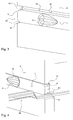
- FIG. 3 and 4 are enlargements of the free ends of recesses (14) and guillotines (1), respectively in the absence and in presence of a tray (20).
- the guillotine (1) rests on the lower wall of the recess (14).
- the rounded (4) cooperates with the chamfer (21) to facilitate insertion initial plateau (20).
- This rounding (4) and the chamfer (21) form in fact together a gap in which is inserted the outer edge of the board (20).
- the guillotine (1) is raised towards the upper wall (19) of the recess (14).
Landscapes
- Engineering & Computer Science (AREA)
- Food Science & Technology (AREA)
- Closures For Containers (AREA)
- Transition And Organic Metals Composition Catalysts For Addition Polymerization (AREA)
- Specific Sealing Or Ventilating Devices For Doors And Windows (AREA)
- Details Of Rigid Or Semi-Rigid Containers (AREA)
Priority Applications (3)
| Application Number | Priority Date | Filing Date | Title |
|---|---|---|---|
| EP03292381A EP1518486B1 (de) | 2003-09-26 | 2003-09-26 | Schützvorrichtung der Schlitze in einer Trennwand tweier kompartimenten |
| DE60329917T DE60329917D1 (de) | 2003-09-26 | 2003-09-26 | Schützvorrichtung der Schlitze in einer Trennwand tweier kompartimenten |
| AT03292381T ATE447347T1 (de) | 2003-09-26 | 2003-09-26 | Schützvorrichtung der schlitze in einer trennwand tweier kompartimenten |
Applications Claiming Priority (1)
| Application Number | Priority Date | Filing Date | Title |
|---|---|---|---|
| EP03292381A EP1518486B1 (de) | 2003-09-26 | 2003-09-26 | Schützvorrichtung der Schlitze in einer Trennwand tweier kompartimenten |
Publications (2)
| Publication Number | Publication Date |
|---|---|
| EP1518486A1 true EP1518486A1 (de) | 2005-03-30 |
| EP1518486B1 EP1518486B1 (de) | 2009-11-04 |
Family
ID=34178654
Family Applications (1)
| Application Number | Title | Priority Date | Filing Date |
|---|---|---|---|
| EP03292381A Expired - Lifetime EP1518486B1 (de) | 2003-09-26 | 2003-09-26 | Schützvorrichtung der Schlitze in einer Trennwand tweier kompartimenten |
Country Status (3)
| Country | Link |
|---|---|
| EP (1) | EP1518486B1 (de) |
| AT (1) | ATE447347T1 (de) |
| DE (1) | DE60329917D1 (de) |
Cited By (1)
| Publication number | Priority date | Publication date | Assignee | Title |
|---|---|---|---|---|
| WO2013098516A1 (fr) | 2011-12-27 | 2013-07-04 | Coldway | Chariot autonome de conditionnement en température et de distribution de plateaux-repas |
Citations (1)
| Publication number | Priority date | Publication date | Assignee | Title |
|---|---|---|---|---|
| WO2000054641A1 (en) * | 1999-03-18 | 2000-09-21 | Enersyst Development Center, L.L.C. | Rethermalization / refrigeration food delivery system |
-
2003
- 2003-09-26 EP EP03292381A patent/EP1518486B1/de not_active Expired - Lifetime
- 2003-09-26 AT AT03292381T patent/ATE447347T1/de not_active IP Right Cessation
- 2003-09-26 DE DE60329917T patent/DE60329917D1/de not_active Expired - Lifetime
Patent Citations (1)
| Publication number | Priority date | Publication date | Assignee | Title |
|---|---|---|---|---|
| WO2000054641A1 (en) * | 1999-03-18 | 2000-09-21 | Enersyst Development Center, L.L.C. | Rethermalization / refrigeration food delivery system |
Cited By (2)
| Publication number | Priority date | Publication date | Assignee | Title |
|---|---|---|---|---|
| WO2013098516A1 (fr) | 2011-12-27 | 2013-07-04 | Coldway | Chariot autonome de conditionnement en température et de distribution de plateaux-repas |
| US9924833B2 (en) | 2011-12-27 | 2018-03-27 | Coldway | Self-contained trolley for temperature conditioning and distribution of meal trays |
Also Published As
| Publication number | Publication date |
|---|---|
| ATE447347T1 (de) | 2009-11-15 |
| DE60329917D1 (de) | 2009-12-17 |
| EP1518486B1 (de) | 2009-11-04 |
Similar Documents
| Publication | Publication Date | Title |
|---|---|---|
| FR2476329A1 (fr) | Boitier pour vues de meme format | |
| CH634973A5 (fr) | Boite a dejeuner pour enfants. | |
| EP3542686A1 (de) | Kochgerät vom typ heissluft-friteuse | |
| EP0850850B1 (de) | Spender für Handschuhe aus Folienmaterial | |
| CA2589628A1 (fr) | Etagere, en particulier pour des installations refrigerees, adaptee pour supporter au moins un accessoire, et accessoires correspondants | |
| FR2703895A1 (fr) | Appareil de cuisson, tel que par exemple une friteuse comportant un dispositif de condensation des vapeurs de cuisson . | |
| EP2818084A1 (de) | Wasserkocher, der mit einer abnehmbaren Staubfilter- und Klappe ausgestattet ist | |
| CH630579A5 (fr) | Support amovible pour la manutention d'un objet. | |
| KR101322408B1 (ko) | 기름유출방지 양면 프라이팬 | |
| FR3100119A1 (fr) | Appareil de cuisson a air chaud avec plusieurs configurations fonctionnelles | |
| EP1518486B1 (de) | Schützvorrichtung der Schlitze in einer Trennwand tweier kompartimenten | |
| EP2058579A2 (de) | Abmontierbare Schutzhülle für Druckbehälter, entsprechendes Werkzeug zum Abmontieren und Verwendung eines solchen Werkzeugs | |
| CH661892A5 (fr) | Rasoir. | |
| EP0802759B2 (de) | Kochgeschirr mit einem griff und mitteln zum halten eines geräts | |
| FR3057149B1 (fr) | Appareil de cuisson, et ensemble incluant cet appareil et une table | |
| FR2649081A1 (fr) | Casier d'emballage et de support d'objets fragiles, en particulier du genre verres a degustation | |
| EP1518487A1 (de) | Tablett mit zwei voneinander trennbaren Bereichen | |
| FR2683139A1 (fr) | Pelle boite de ramassage de dechets animaux ou domestiques avec distributeur integre de sacs protecteurs. | |
| EP3056319A1 (de) | Vorrichtung zur Aufbewahrung von Instrumenten mit Klingen, und Werkzeugkasten, der mit einer solchen Vorrichtung ausgestattet ist | |
| EP1302142B1 (de) | Speichervorrichtung für Pfännchen für ein Raclettegerät und Raclettegerät mit einer solchen Vorrichtung | |
| FR2733309A3 (fr) | Appareil electromenager, en particulier un appareil de refrigeration, comportant un element de support, tel qu'un recipient alimentaire, des bouteilles ou equivalent, relies magnetiquement au dit appareil | |
| EP1449785A1 (de) | Befestigungselement für einen Kunststoffdeckel auf einen Kunststoffbehälter zur Vakuumverpackung von Gegenständen in loser Schüttung im Behälter | |
| FR2741794A1 (fr) | Dispositif pour la preparation de brochettes | |
| FR2928627A1 (fr) | Recipient en matiere plastique moulee muni d'un dispositif pour la fixation sur sa paroi d'un objet presentant au moins une portion plate. | |
| WO2004011277A2 (fr) | Bac de mouillage pour pinceau et boite de peinture equipee dudit bac |
Legal Events
| Date | Code | Title | Description |
|---|---|---|---|
| PUAI | Public reference made under article 153(3) epc to a published international application that has entered the european phase |
Free format text: ORIGINAL CODE: 0009012 |
|
| 17P | Request for examination filed |
Effective date: 20031015 |
|
| AK | Designated contracting states |
Kind code of ref document: A1 Designated state(s): AT BE BG CH CY CZ DE DK EE ES FI FR GB GR HU IE IT LI LU MC NL PT RO SE SI SK TR |
|
| AX | Request for extension of the european patent |
Extension state: AL LT LV MK |
|
| AKX | Designation fees paid |
Designated state(s): AT BE BG CH CY CZ DE DK EE ES FI FR GB GR HU IE IT LI LU MC NL PT RO SE SI SK TR |
|
| 17Q | First examination report despatched |
Effective date: 20041118 |
|
| GRAP | Despatch of communication of intention to grant a patent |
Free format text: ORIGINAL CODE: EPIDOSNIGR1 |
|
| GRAJ | Information related to disapproval of communication of intention to grant by the applicant or resumption of examination proceedings by the epo deleted |
Free format text: ORIGINAL CODE: EPIDOSDIGR1 |
|
| GRAP | Despatch of communication of intention to grant a patent |
Free format text: ORIGINAL CODE: EPIDOSNIGR1 |
|
| GRAS | Grant fee paid |
Free format text: ORIGINAL CODE: EPIDOSNIGR3 |
|
| GRAA | (expected) grant |
Free format text: ORIGINAL CODE: 0009210 |
|
| AK | Designated contracting states |
Kind code of ref document: B1 Designated state(s): AT BE BG CH CY CZ DE DK EE ES FI FR GB GR HU IE IT LI LU MC NL PT RO SE SI SK TR |
|
| REG | Reference to a national code |
Ref country code: GB Ref legal event code: FG4D Free format text: NOT ENGLISH |
|
| REG | Reference to a national code |
Ref country code: CH Ref legal event code: EP |
|
| REG | Reference to a national code |
Ref country code: IE Ref legal event code: FG4D |
|
| REF | Corresponds to: |
Ref document number: 60329917 Country of ref document: DE Date of ref document: 20091217 Kind code of ref document: P |
|
| NLV1 | Nl: lapsed or annulled due to failure to fulfill the requirements of art. 29p and 29m of the patents act | ||
| PG25 | Lapsed in a contracting state [announced via postgrant information from national office to epo] |
Ref country code: ES Free format text: LAPSE BECAUSE OF FAILURE TO SUBMIT A TRANSLATION OF THE DESCRIPTION OR TO PAY THE FEE WITHIN THE PRESCRIBED TIME-LIMIT Effective date: 20100215 Ref country code: PT Free format text: LAPSE BECAUSE OF FAILURE TO SUBMIT A TRANSLATION OF THE DESCRIPTION OR TO PAY THE FEE WITHIN THE PRESCRIBED TIME-LIMIT Effective date: 20100304 Ref country code: FI Free format text: LAPSE BECAUSE OF FAILURE TO SUBMIT A TRANSLATION OF THE DESCRIPTION OR TO PAY THE FEE WITHIN THE PRESCRIBED TIME-LIMIT Effective date: 20091104 Ref country code: SE Free format text: LAPSE BECAUSE OF FAILURE TO SUBMIT A TRANSLATION OF THE DESCRIPTION OR TO PAY THE FEE WITHIN THE PRESCRIBED TIME-LIMIT Effective date: 20091104 |
|
| REG | Reference to a national code |
Ref country code: IE Ref legal event code: FD4D |
|
| PG25 | Lapsed in a contracting state [announced via postgrant information from national office to epo] |
Ref country code: CY Free format text: LAPSE BECAUSE OF FAILURE TO SUBMIT A TRANSLATION OF THE DESCRIPTION OR TO PAY THE FEE WITHIN THE PRESCRIBED TIME-LIMIT Effective date: 20091104 Ref country code: SI Free format text: LAPSE BECAUSE OF FAILURE TO SUBMIT A TRANSLATION OF THE DESCRIPTION OR TO PAY THE FEE WITHIN THE PRESCRIBED TIME-LIMIT Effective date: 20091104 |
|
| PG25 | Lapsed in a contracting state [announced via postgrant information from national office to epo] |
Ref country code: AT Free format text: LAPSE BECAUSE OF FAILURE TO SUBMIT A TRANSLATION OF THE DESCRIPTION OR TO PAY THE FEE WITHIN THE PRESCRIBED TIME-LIMIT Effective date: 20091104 |
|
| PG25 | Lapsed in a contracting state [announced via postgrant information from national office to epo] |
Ref country code: EE Free format text: LAPSE BECAUSE OF FAILURE TO SUBMIT A TRANSLATION OF THE DESCRIPTION OR TO PAY THE FEE WITHIN THE PRESCRIBED TIME-LIMIT Effective date: 20091104 Ref country code: DK Free format text: LAPSE BECAUSE OF FAILURE TO SUBMIT A TRANSLATION OF THE DESCRIPTION OR TO PAY THE FEE WITHIN THE PRESCRIBED TIME-LIMIT Effective date: 20091104 Ref country code: IE Free format text: LAPSE BECAUSE OF FAILURE TO SUBMIT A TRANSLATION OF THE DESCRIPTION OR TO PAY THE FEE WITHIN THE PRESCRIBED TIME-LIMIT Effective date: 20091104 Ref country code: BG Free format text: LAPSE BECAUSE OF FAILURE TO SUBMIT A TRANSLATION OF THE DESCRIPTION OR TO PAY THE FEE WITHIN THE PRESCRIBED TIME-LIMIT Effective date: 20100204 Ref country code: RO Free format text: LAPSE BECAUSE OF FAILURE TO SUBMIT A TRANSLATION OF THE DESCRIPTION OR TO PAY THE FEE WITHIN THE PRESCRIBED TIME-LIMIT Effective date: 20091104 |
|
| PG25 | Lapsed in a contracting state [announced via postgrant information from national office to epo] |
Ref country code: CZ Free format text: LAPSE BECAUSE OF FAILURE TO SUBMIT A TRANSLATION OF THE DESCRIPTION OR TO PAY THE FEE WITHIN THE PRESCRIBED TIME-LIMIT Effective date: 20091104 Ref country code: SK Free format text: LAPSE BECAUSE OF FAILURE TO SUBMIT A TRANSLATION OF THE DESCRIPTION OR TO PAY THE FEE WITHIN THE PRESCRIBED TIME-LIMIT Effective date: 20091104 |
|
| PLBE | No opposition filed within time limit |
Free format text: ORIGINAL CODE: 0009261 |
|
| STAA | Information on the status of an ep patent application or granted ep patent |
Free format text: STATUS: NO OPPOSITION FILED WITHIN TIME LIMIT |
|
| 26N | No opposition filed |
Effective date: 20100805 |
|
| PG25 | Lapsed in a contracting state [announced via postgrant information from national office to epo] |
Ref country code: GR Free format text: LAPSE BECAUSE OF FAILURE TO SUBMIT A TRANSLATION OF THE DESCRIPTION OR TO PAY THE FEE WITHIN THE PRESCRIBED TIME-LIMIT Effective date: 20100205 |
|
| BERE | Be: lapsed |
Owner name: SOCAMEL S.A.S. Effective date: 20100930 |
|
| PG25 | Lapsed in a contracting state [announced via postgrant information from national office to epo] |
Ref country code: IT Free format text: LAPSE BECAUSE OF FAILURE TO SUBMIT A TRANSLATION OF THE DESCRIPTION OR TO PAY THE FEE WITHIN THE PRESCRIBED TIME-LIMIT Effective date: 20091104 |
|
| PG25 | Lapsed in a contracting state [announced via postgrant information from national office to epo] |
Ref country code: MC Free format text: LAPSE BECAUSE OF NON-PAYMENT OF DUE FEES Effective date: 20100930 |
|
| REG | Reference to a national code |
Ref country code: CH Ref legal event code: PL |
|
| GBPC | Gb: european patent ceased through non-payment of renewal fee |
Effective date: 20100926 |
|
| REG | Reference to a national code |
Ref country code: DE Ref legal event code: R119 Ref document number: 60329917 Country of ref document: DE Effective date: 20110401 |
|
| PG25 | Lapsed in a contracting state [announced via postgrant information from national office to epo] |
Ref country code: CH Free format text: LAPSE BECAUSE OF NON-PAYMENT OF DUE FEES Effective date: 20100930 Ref country code: DE Free format text: LAPSE BECAUSE OF NON-PAYMENT OF DUE FEES Effective date: 20110401 Ref country code: BE Free format text: LAPSE BECAUSE OF NON-PAYMENT OF DUE FEES Effective date: 20100930 Ref country code: LI Free format text: LAPSE BECAUSE OF NON-PAYMENT OF DUE FEES Effective date: 20100930 |
|
| PG25 | Lapsed in a contracting state [announced via postgrant information from national office to epo] |
Ref country code: GB Free format text: LAPSE BECAUSE OF NON-PAYMENT OF DUE FEES Effective date: 20100926 |
|
| PG25 | Lapsed in a contracting state [announced via postgrant information from national office to epo] |
Ref country code: NL Free format text: LAPSE BECAUSE OF FAILURE TO SUBMIT A TRANSLATION OF THE DESCRIPTION OR TO PAY THE FEE WITHIN THE PRESCRIBED TIME-LIMIT Effective date: 20091104 Ref country code: LU Free format text: LAPSE BECAUSE OF NON-PAYMENT OF DUE FEES Effective date: 20100926 Ref country code: HU Free format text: LAPSE BECAUSE OF FAILURE TO SUBMIT A TRANSLATION OF THE DESCRIPTION OR TO PAY THE FEE WITHIN THE PRESCRIBED TIME-LIMIT Effective date: 20100505 |
|
| PG25 | Lapsed in a contracting state [announced via postgrant information from national office to epo] |
Ref country code: TR Free format text: LAPSE BECAUSE OF FAILURE TO SUBMIT A TRANSLATION OF THE DESCRIPTION OR TO PAY THE FEE WITHIN THE PRESCRIBED TIME-LIMIT Effective date: 20091104 |
|
| REG | Reference to a national code |
Ref country code: FR Ref legal event code: PLFP Year of fee payment: 13 |
|
| REG | Reference to a national code |
Ref country code: FR Ref legal event code: PLFP Year of fee payment: 14 |
|
| REG | Reference to a national code |
Ref country code: FR Ref legal event code: PLFP Year of fee payment: 15 |
|
| REG | Reference to a national code |
Ref country code: FR Ref legal event code: PLFP Year of fee payment: 16 |
|
| PGFP | Annual fee paid to national office [announced via postgrant information from national office to epo] |
Ref country code: FR Payment date: 20220822 Year of fee payment: 20 |