EP1518486B1 - Schützvorrichtung der Schlitze in einer Trennwand tweier kompartimenten - Google Patents
Schützvorrichtung der Schlitze in einer Trennwand tweier kompartimenten Download PDFInfo
- Publication number
- EP1518486B1 EP1518486B1 EP03292381A EP03292381A EP1518486B1 EP 1518486 B1 EP1518486 B1 EP 1518486B1 EP 03292381 A EP03292381 A EP 03292381A EP 03292381 A EP03292381 A EP 03292381A EP 1518486 B1 EP1518486 B1 EP 1518486B1
- Authority
- EP
- European Patent Office
- Prior art keywords
- guillotine
- slots
- occluding
- stud
- orifice
- Prior art date
- Legal status (The legal status is an assumption and is not a legal conclusion. Google has not performed a legal analysis and makes no representation as to the accuracy of the status listed.)
- Expired - Lifetime
Links
- 230000000903 blocking effect Effects 0.000 title abstract 2
- 235000012054 meals Nutrition 0.000 claims abstract description 8
- 238000003860 storage Methods 0.000 claims abstract description 3
- 238000005192 partition Methods 0.000 claims description 11
- 230000005484 gravity Effects 0.000 claims description 6
- 238000006073 displacement reaction Methods 0.000 claims description 4
- 230000000694 effects Effects 0.000 claims description 4
- 229920003023 plastic Polymers 0.000 claims description 3
- 239000004033 plastic Substances 0.000 claims description 3
- 230000008878 coupling Effects 0.000 claims description 2
- 238000010168 coupling process Methods 0.000 claims description 2
- 238000005859 coupling reaction Methods 0.000 claims description 2
- 230000002349 favourable effect Effects 0.000 claims description 2
- 230000002093 peripheral effect Effects 0.000 claims description 2
- 230000007704 transition Effects 0.000 claims 1
- 238000009826 distribution Methods 0.000 abstract description 3
- 235000013305 food Nutrition 0.000 description 9
- 238000004140 cleaning Methods 0.000 description 4
- 238000003780 insertion Methods 0.000 description 4
- 230000037431 insertion Effects 0.000 description 4
- 238000000926 separation method Methods 0.000 description 4
- 230000036541 health Effects 0.000 description 3
- 241001080024 Telles Species 0.000 description 2
- 230000004888 barrier function Effects 0.000 description 2
- 238000000605 extraction Methods 0.000 description 2
- 230000000284 resting effect Effects 0.000 description 2
- 238000007789 sealing Methods 0.000 description 2
- 230000006399 behavior Effects 0.000 description 1
- 230000000295 complement effect Effects 0.000 description 1
- 230000001419 dependent effect Effects 0.000 description 1
- 238000005304 joining Methods 0.000 description 1
- 239000000463 material Substances 0.000 description 1
- 238000000034 method Methods 0.000 description 1
- 238000005036 potential barrier Methods 0.000 description 1
- 230000008569 process Effects 0.000 description 1
- 238000003303 reheating Methods 0.000 description 1
- 238000005096 rolling process Methods 0.000 description 1
- 238000004659 sterilization and disinfection Methods 0.000 description 1
Images

Classifications
-
- A—HUMAN NECESSITIES
- A47—FURNITURE; DOMESTIC ARTICLES OR APPLIANCES; COFFEE MILLS; SPICE MILLS; SUCTION CLEANERS IN GENERAL
- A47J—KITCHEN EQUIPMENT; COFFEE MILLS; SPICE MILLS; APPARATUS FOR MAKING BEVERAGES
- A47J39/00—Heat-insulated warming chambers; Cupboards with heating arrangements for warming kitchen utensils
- A47J39/006—Heat-insulated warming chambers; Cupboards with heating arrangements for warming kitchen utensils for either storing and preparing or for preparing food on serving trays, e.g. heating, thawing, preserving
Definitions
- the present invention relates in the first place to a closure system of slots made in a vertical wall separating two compartments.
- a closure system of slots made in a vertical wall separating two compartments.
- Such a system is particularly suitable for use in rolling trolleys for storing meal trays for distribution in the rooms of an establishment, for example of the hospital type, said trolleys constituting another part of the invention.
- trolleys consist mainly of a thermally insulated container, whose bottom is equipped with wheels for transporting them in the establishment, and whose upper part comprises at least one gripping member for the user to guide them.
- the container is composed of two compartments separated by a central wall acting as a thermal barrier, because one of the compartments is kept at low temperature while the other is heated.
- the food allocated to a patient is usually placed on a single tray.
- Foods for reheating are grouped on one side, while foods that need to be kept warm are on the other side.
- the central portion of the tray is then inserted into a horizontal slot made in the partition wall between the cold and hot compartments, so that each dish is found in the thermally appropriate zone, and that it can be distributed at the temperature of consumption.
- the central wall serves as a thermal barrier and must prevent inadvertent thermal transfer between the compartments.
- the cold compartment is ventilated, and maintained at a temperature between 0 and 4 ° C.
- the hot compartment also ventilated, must be maintained at a temperature between 85 and 140 ° C.
- These temperatures are imposed by standards very strict sanitary conditions which set minimum temperature thresholds on the hot side and maximum on the cold side, in order to guarantee the food safety of the proposed foods. According to these standards, hygiene is ensured when the core temperature of food is 63 ° C hot side, while it is only 8 ° C cold side.
- the carriage is filled with a stack of trays arranged on side racks, whose central portion is inserted into said slots placed at regular intervals over the entire height of the wall of separation.
- the trays are, in general, separated by a distance of the order of 85 to 110 mm.
- a slot closure system made in a vertical wall separating two compartments, comprising for each slot a removable movable guillotine between a rest position closing the slot and a position released from said slot, the passage from the unobstructed position to the closed position being effected under the effect of gravity, the coupling means of the guillotine and the wall comprising at least one stud projecting from said wall and guided in a complex orifice made in the guillotine so that on the one hand that the disassembly / reassembly of the guillotine from / to the wall is done manually by simple cooperation between the stud and the orifice, and secondly that the displacement of the guillotine between the closed and unobstructed positions is ensured, the orifice complex comprising a first guide portion for moving the guillotine between its two closed and unobstructed positions but not its separation of the stud, said guide portion being connected to a second
- the invention relates to a slit shutter system according to claim 1.
- the function provided by the cooperation between the stud and the orifice will be different. In one case, it will be a simple guide ensuring the sealing function between the compartments, whether or not there is a tray in the slot, while in the other case, it will be to allow disassembly of the guillotine for example for cleaning.
- the complex orifice comprises a first guiding portion allowing the displacement of the guillotine between its two positions closed and disengaged but not its separation from the stud, said guiding portion being linked to a second portion of assembly / disassembly in which the operation of securing / disconnecting the stud and the guillotine is possible.
- the guide portion and the securing / disengaging portion of the orifice are connected by an intermediate portion to shift them so that the position of the guillotine is favorable to its handling when the stud is in the portion securing / detaching, in order to facilitate the assembly / dismounting operation of the guillotine.
- This feature is not strictly necessary for accomplishing the primary functions of the system of the invention, namely guiding the guillotine between its two positions on the one hand, and its dismountability on the other hand, but it allows to make the job easier for the operator.
- This is the incentive aspect mentioned earlier, which aims to remove potential barriers in performing cleaning / disinfection tasks to meet current standards.
- the stud comprises a shaft fixed perpendicularly to the wall, whose free end is provided with a cap of diameter greater than that of the shaft.
- the configuration of the complex orifice depends of course on the shape that is given to the projecting stud.
- the guide portion in the orifice, consists of a slide whose width, over at least a portion of its depth, is smaller than the diameter of the cap and greater than that of the stud shaft.
- its purpose is to allow guiding the guillotine in a direction of pace perpendicular to the slot, that is to say generally vertical, so that the tray, when inserted, can lift said guillotine and that it can, if necessary, descend by gravity to its contact.
- the securing portion / uncoupling of the orifice has, over its entire depth, larger dimensions than the diameter of the cap.
- this securing portion / separation of the complex orifice is preferably provided cylindrical, and diameter of course greater than that of the cap.
- the intermediate portion of the complex orifice consists of a slide which develops substantially parallel to the axis of the slot, opens at its two ends respectively in the guide portion and in the securing portion and has, on at least part of its depth, a width less than the diameter of the cap and greater than that of the stud shaft.
- This intermediate portion is actually used to extract the side edge of the wall one end of the guillotine, in order to handle it more easily, as will become clearer in the following.
- the respective shapes of the stud and the different portions could allow the use of a non-through complex orifice, which would then be provided, in its guiding and intermediate portions, in the vicinity of its bottom, with a portion of greater width allowing to accommodate the cap of the stud.
- the orifice passes through the guillotine, and its respective guide and intermediate portions have a width less than the diameter of the cap and greater than that of the shaft over their entire depth.
- This configuration is particularly much simpler to implement when joining the guillotine on the or pads.
- the slide forming the intermediate portion of the complex orifice is centered relative to the portions in which it opens.
- the complex orifice as it is then drawn, takes the form of a key.
- the guillotine further comprises, in the vicinity of its end located in the extension of the guide portion, a recess for facilitating its grip.
- This recess is especially useful for the first extraction movement, parallel to the axis of the slot. Then, said end being extracted from the wall, it offers a grip to the user to proceed to complete disassembly of the guillotine.
- each guillotine is disposed in a recess of the wall in the bottom of which is on the one hand the slot and secondly the area of attachment of the pad or pads, and whose depth is provided so that, when the guillotine is secured therein, it is completely housed, or even flush with the outer surface of the wall.
- this recess opens into the side edge of the wall.
- the disassembly with the complex plot / orifice system as described above, could also be provided with a recess longer than the length of the guillotine, a value at least equal to the length of the intermediate portion of the orifice, without this recess emerges on one of the lateral edges of the wall.
- a recess longer than the length of the guillotine a value at least equal to the length of the intermediate portion of the orifice, without this recess emerges on one of the lateral edges of the wall.
- the guillotine is made of food plastic, as well as the fixing studs.
- the invention also relates to a trolley for storing and distributing meal trays comprising a storage enclosure separated by a vertical wall in two compartments maintained respectively at high and low temperature, said wall having slots in which the trays are inserted, said slots being closable by a system as described above.
- the slots in the vertical wall are arranged horizontally.
- the guillotines of the shutter system of the slots are arranged in the compartment maintained at low temperature.
- the trays comprise a totally flat bottom, of constant thickness less than the height of the slots, and have no peripheral edge in the central part of the sides perpendicular to the slot, over a distance equal to several times the thickness of the central wall.
- This configuration allows a travel of the tray giving the user a possibility of choosing the surface affected food to heat or keep cold.
- each guillotine (1) is in fact constituted by an elongate bar of substantially rectangular cross-section, provided in its central part with a hole (2) of complex shape, and towards one of its ends, with a recess (3) whose function will appear later.
- the connection areas (4, 5, 6, 7) between the large and small edges of the guillotine (1) are rounded for reasons that will be detailed in the following description.
- the complex orifice (2) consists of a guide portion (8), of vertical shape, connected by an intermediate portion (9) of horizontal shape to a cylindrical portion (10) of diameter greater than the widths of the two portions (8, 9) above. This diameter must allow the passage of a cap (12) of a stud (11) also provided with a shaft (13) intended to be guided inside the guide portions (8) and intermediate (9) of the complex orifice (2).
- This stud (11) is intended to be fixed on the wall (P) constituting the bottom of the recess (14) in which the guillotine (1) takes place.
- the entire volume of the guillotine (1) is housed in said recess (14). It comprises, in the lower part of the bottom wall (15), a slot (16) that the guillotine (1) allows to close.
- the stud (11) is fixed to the bottom (15) so that when it is accommodated in the guide portion (8) of the complex orifice (2), the end (E1) of the guillotine remains contained in the volume of the recess (14), while the end (E2) is substantially in abutment with the wall (17) of the recess (14).
- the relative positioning of the stud (11) fixed to the bottom (15) and of its guiding portion (8) in the guillotine (1) is such that when the recess (14) is empty, that is to say for example in the absence of trays (20), the guillotine (1) falls by gravity in contact with the wall (P) of the recess (14).
- the figure 2 shows on its left side, guillotines (1) in the rest position in contact with the lower wall (18) of the recess (14), that is to say in the closed position of the slot (16). ).
- the guillotines (1) are well contained in their entirety in the recesses (14) made in the wall (P). In this position, there is of course the possibility of movement of the guillotines (1) upwards, to unclog the slots (16).
- the shaft (13) of the pads (11) is in this case in the upper portion of the guide portion (8) of the complex orifices (2), to allow to lift the guillotines (1).
- the caps (12) of the pads (11) prevent the guillotines (1) are disassembled when they are in this position.
- trays (20) have been inserted in the slots (16), which results in lifting the strips (1), in the direction of the upper wall (19) of the recess (14).
- the lifting of the guillotine (1) is done automatically at the insertion, due to the existence of one of the roundings (4, 5) located at the end (E1) and a chamfer (21).
- the same guillotine (1) being usable on both sides of the wall (P), since it has a symmetry with respect to a longitudinal median plane, it is the rounded (4) that can first come into contact with the plate (20) in the right part of the wall (P), while it is the rounded part (5) which would in this case come into contact with a plate (20) in the left part.
- the guillotine (1) is lifted gradually, in particular by pivoting initially with respect to the axis formed by the shaft (13) housed in the guiding portion (8). ) of the complex orifice (2).
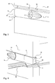
- FIGs 3 and 4 are enlargements of the free ends of the recesses (14) and guillotines (1), respectively in the absence and in presence of a tray (20).
- the guillotine (1) rests on the lower wall of the recess (14).
- the rounding (4) cooperates with the chamfer (21) to facilitate the initial insertion of the plate (20).
- This rounding (4) and the chamfer (21) form together a gap in which is inserted the outer edge of the plate (20).
- the guillotine (1) is raised towards the upper wall (19) of the recess (14).
Landscapes
- Engineering & Computer Science (AREA)
- Food Science & Technology (AREA)
- Closures For Containers (AREA)
- Transition And Organic Metals Composition Catalysts For Addition Polymerization (AREA)
- Specific Sealing Or Ventilating Devices For Doors And Windows (AREA)
- Details Of Rigid Or Semi-Rigid Containers (AREA)
Claims (16)
- System zum Verschließen von Schlitzen (16), die in einer vertikalen Wand (P) vorgesehen sind, die zwei Abteile trennt, welches für jeden Schlitz (16) eine herausnehmbare Falleinrichtung (1) aufweist, die zwischen einer Ruheposition, in der der Schlitz (16) verschlossen ist, und einer von dem Schlitz (16) entfernten Position beweglich ist, wobei der Übergang von der entfernten zu der verschlossenen Position unter Wirkung der Schwerkraft bewirkt wird, wobei die Mittel zum Verbinden der Falleinrichtung (1) und der Wand (P) wenigstens einen Stift (11) aufweisen, der aus der Wand (P) hervorsteht und in einer komplexen Öffnung (2) geführt wird, die in der Falleinrichtung (1) vorgesehen ist, derart, dass einerseits das Ausbauen / Einbauen der Falleinrichtung (1) aus der / in die Wand (P) manuell durch einfaches Zusammenwirken des Stifts (11) und der Öffnung (2) bewirkt wird, und andererseits das Verschieben der Falleinrichtung (1) zwischen der verschließenden und entfernten Position gewährleistet wird, wobei die komplexe Öffnung (2) einen ersten Führungsabschnitt (8) aufweist, der das Verschieben der Falleinrichtung (1) zwischen ihren zwei Positionen, der verschließenden und der entfernten, ermöglicht, aber nicht deren Lösen von dem Stift, wobei der Führungsabschnitt (8) mit einem zweiten Abschnitt (10) zum Einbauen / Ausbauen verbunden ist, in dem der Vorgang des Verbindens / Lösens des Stifts (11) mit / von der Falleinrichtung (1) möglich ist, dadurch gekennzeichnet, dass der Führungsabschnitt (8) und der Einbau-/ Ausbauabschnitt (10) der Öffnung (2) durch einen Zwischenabschnitt (9) verbunden sind, der es ermöglicht, diese derart zu versetzen, dass die Position der Falleinrichtung (1) deren Handhabung erleichtert, während sich der Stift in dem Befestigungs- / Lösungsabschnitt befindet, um den Vorgang des Einbauens / Ausbauens der Falleinrichtung (1) zu erleichtern, wobei der Zwischenabschnitt (9) aus einer Laufschiene besteht, die sich im Wesentlichen parallel zum Schlitz (16) verläuft.
- System zum Verschließen von Schlitzen gemäß Anspruch 1, dadurch gekennzeichnet, dass der Stift (11) eine feststehende Achse (13) senkrecht zur Wand (P) aufweist, deren freies Ende mit einer Kappe (12) versehen ist, deren Durchmesser größer als jener der Achse (13) ist.
- System zum Verschließen von Schlitzen gemäß dem vorstehenden Anspruch, dadurch gekennzeichnet, dass der Führungsabschnitt (8) in der komplexen Öffnung (2) aus einer Laufschiene besteht, deren Breite wenigstens auf einem Teil ihrer Tiefe kleiner ist als der Durchmesser der Kappe und größer ist als jener der Achse (13) des Stifts (11).
- System zum Verschließen von Schlitzen gemäß einem der Ansprüche 2 oder 3, dadurch gekennzeichnet, dass der Befestigungs-/ Lösungsabschnitt (10) der Öffnung (2) auf seiner gesamten Tiefe größere Abmessungen aufweist als der Durchmesser der Kappe (12).
- System zum Verschließen von Schlitzen gemäß dem vorstehenden Anspruch, dadurch gekennzeichnet, dass der Befestigungs-/ Lösungsabschnitt (10) zylindrisch ist und sein Durchmesser größer ist als jener der Kappe (12).
- System zum Verschließen von Schlitzen gemäß einem der Ansprüche 3 bis 5, dadurch gekennzeichnet, dass der Zwischenabschnitt (9) der komplexen Öffnung (2) aus einer Laufschiene besteht, die im Wesentlichen parallel zur Achse des Schlitzes (16) verläuft und an ihren beiden Enden jeweils in den Führungsabschnitt (8) und in den Befestigungsabschnitt (10) mündet und wenigstens auf einem Teil ihrer Tiefe eine Breite aufweist, die kleiner ist als der Durchmesser der Kappe (12) und größer ist als jener der Achse (13) des Stifts (12).
- System zum Verschließen von Schlitzen gemäß einem der Ansprüche 2 bis 6, dadurch gekennzeichnet, dass die Öffnung (2) durch die Falleinrichtung (1) geht, und ihr entsprechender Führungsabschnitt (8) und Zwischenabschnitt (9) über deren gesamte Tiefe eine Breite aufweisen, die kleiner ist als der Durchmesser der Kappe (12) und größer ist als jener der Achse (13).
- System zum Verschließen von Schlitzen gemäß einem der Ansprüche 6 oder 7, dadurch gekennzeichnet, dass die Laufschiene, die den Zwischenabschnitt der komplexen Öffnung (2) bildet, bezogen auf die Abschnitte (8, 10), in denen sie mündet, mittig ist.
- System zum Verschließen von Schlitzen gemäß einem der Ansprüche 2 bis 8, dadurch gekennzeichnet, dass die Falleinrichtung (1) in der Nähe ihres in der Verlängerung des Führungsabschnitts (8) angeordneten Endes eine Aussparung (3) aufweist, die zur Erleichterung des Greifens dient.
- System zum Verschließen von Schlitzen gemäß dem vorstehenden Anspruch, dadurch gekennzeichnet, dass jede Falleinrichtung (1) in einer Aussparung (14) der Wand (P) angeordnet ist, in deren Boden (15) sich einerseits der Schlitz (16) und andererseits die Zone zum Befestigen des oder der Stifte (11) befinden, und deren Tiefe derart vorgesehen ist, dass, wenn die Falleinrichtung (1) damit verbunden ist, sie in dem Sitz enthalten ist.
- System zum Verschließen von Schlitzen gemäß dem vorstehenden Anspruch, dadurch gekennzeichnet, dass die Aussparung (14) in die Seitenkante der Wand (P) auf der Seite des Endes der Falleinrichtung (1), die in der Verlängerung des Führungsabschnitts (8) der komplexen Öffnung (2) angeordnet ist, mündet.
- System zum Verschließen von Schlitzen gemäß einem der Ansprüche 2 bis 11, dadurch gekennzeichnet, dass die Falleinrichtung (1) ebenso wie der oder die Stifte (11) aus einem nahrungsmittelechten Kunststoff hergestellt sind.
- Wagen zum Lagern und Verteilen von Tabletts (20) für Mahlzeiten, welcher einen Lagerraum aufweist, der mittels einer senkrechten Wand (P) in zwei Abteile geteilt ist, die jeweils bei einer hohen und einer niedrigen Temperatur gehalten werden, wobei die Wand Schlitze (16) aufweist, in die die Tabletts eingesetzt werden, wobei die Schlitze (16) mittels eines Systems gemäß einem der vorstehenden Ansprüche verschlossen werden.
- Wagen zum Lagern und Verteilen von Tabletts (20) für Mahlzeiten gemäß dem vorstehenden Anspruch, dadurch gekennzeichnet, dass die Schlitze (16) waagerecht sind.
- Wagen zum Lagern und Verteilen von Tabletts (20) für Mahlzeiten gemäß einem der Ansprüche 13 oder 14, dadurch gekennzeichnet, dass die Falleinrichtungen (1) des Systems zum Verschließen von Schlitzen (16) in dem Abteil angeordnet sind, das bei niedriger Temperatur gehalten wird.
- Wagen zum Lagern und Verteilen von Tabletts (20) für Mahlzeiten gemäß einem der Ansprüche 13 bis 15, dadurch gekennzeichnet, dass die Tabletts (20) einen vollkommen ebenen Boden aufweisen mit einer gleichbleibenden Dicke, die geringer ist als die Höhe der Schlitze, und sie mit einem umlaufenden Rand in dem mittleren Teil der Seiten senkrecht zum Schlitz (16) mit einem Abstand, der das Mehrfache der Dicke der Mittelwand beträgt, versehen sind.
Priority Applications (3)
| Application Number | Priority Date | Filing Date | Title |
|---|---|---|---|
| EP03292381A EP1518486B1 (de) | 2003-09-26 | 2003-09-26 | Schützvorrichtung der Schlitze in einer Trennwand tweier kompartimenten |
| DE60329917T DE60329917D1 (de) | 2003-09-26 | 2003-09-26 | Schützvorrichtung der Schlitze in einer Trennwand tweier kompartimenten |
| AT03292381T ATE447347T1 (de) | 2003-09-26 | 2003-09-26 | Schützvorrichtung der schlitze in einer trennwand tweier kompartimenten |
Applications Claiming Priority (1)
| Application Number | Priority Date | Filing Date | Title |
|---|---|---|---|
| EP03292381A EP1518486B1 (de) | 2003-09-26 | 2003-09-26 | Schützvorrichtung der Schlitze in einer Trennwand tweier kompartimenten |
Publications (2)
| Publication Number | Publication Date |
|---|---|
| EP1518486A1 EP1518486A1 (de) | 2005-03-30 |
| EP1518486B1 true EP1518486B1 (de) | 2009-11-04 |
Family
ID=34178654
Family Applications (1)
| Application Number | Title | Priority Date | Filing Date |
|---|---|---|---|
| EP03292381A Expired - Lifetime EP1518486B1 (de) | 2003-09-26 | 2003-09-26 | Schützvorrichtung der Schlitze in einer Trennwand tweier kompartimenten |
Country Status (3)
| Country | Link |
|---|---|
| EP (1) | EP1518486B1 (de) |
| AT (1) | ATE447347T1 (de) |
| DE (1) | DE60329917D1 (de) |
Families Citing this family (1)
| Publication number | Priority date | Publication date | Assignee | Title |
|---|---|---|---|---|
| FR2985003A1 (fr) | 2011-12-27 | 2013-06-28 | Coldway | Dispositif de chauffage et de refrigeration simultane de deux volumes |
Family Cites Families (1)
| Publication number | Priority date | Publication date | Assignee | Title |
|---|---|---|---|---|
| JP2002539412A (ja) * | 1999-03-18 | 2002-11-19 | エナシスト、ディヴェラップマント、センタ、エル、エル、シー | 再加熱/冷凍食品送出しシステム |
-
2003
- 2003-09-26 EP EP03292381A patent/EP1518486B1/de not_active Expired - Lifetime
- 2003-09-26 AT AT03292381T patent/ATE447347T1/de not_active IP Right Cessation
- 2003-09-26 DE DE60329917T patent/DE60329917D1/de not_active Expired - Lifetime
Also Published As
| Publication number | Publication date |
|---|---|
| ATE447347T1 (de) | 2009-11-15 |
| EP1518486A1 (de) | 2005-03-30 |
| DE60329917D1 (de) | 2009-12-17 |
Similar Documents
| Publication | Publication Date | Title |
|---|---|---|
| BE1005930A3 (fr) | Necesaire pour boite a casse-croute. | |
| EP0850850B1 (de) | Spender für Handschuhe aus Folienmaterial | |
| CH634973A5 (fr) | Boite a dejeuner pour enfants. | |
| EP3450855A1 (de) | Abdeckelement für eine öffnung eines backhohlraums eines miniofens | |
| FR2703895A1 (fr) | Appareil de cuisson, tel que par exemple une friteuse comportant un dispositif de condensation des vapeurs de cuisson . | |
| WO2014096713A1 (fr) | Appareil de decoupe d'aliments a mouvement alternatif avec recipient amovible lavable | |
| CH630579A5 (fr) | Support amovible pour la manutention d'un objet. | |
| EP2818084A1 (de) | Wasserkocher, der mit einer abnehmbaren Staubfilter- und Klappe ausgestattet ist | |
| EP1518486B1 (de) | Schützvorrichtung der Schlitze in einer Trennwand tweier kompartimenten | |
| EP2058579A2 (de) | Abmontierbare Schutzhülle für Druckbehälter, entsprechendes Werkzeug zum Abmontieren und Verwendung eines solchen Werkzeugs | |
| EP2941161B1 (de) | Lebensmittelzubereitungsvorrichtung mit einer halterung zur anbringung eines abnehmbaren reinigungszubehörs | |
| EP3501371A1 (de) | Waschtank einer geschirrspülmaschine, der eine ausrastvorrichtung umfasst | |
| FR2644564A3 (fr) | Armoire frigorifique comportant, agences les uns au-dessus des autres dans son enceinte, plusieurs moyens de rangement du genre tiroir | |
| EP1518487A1 (de) | Tablett mit zwei voneinander trennbaren Bereichen | |
| EP4027941A1 (de) | Vorrichtung zum handhaben von mehreren halmen zum verpacken von tiersamen | |
| FR3053031B1 (fr) | Perfectionnement de couvercle recipient | |
| EP4027940B1 (de) | Anordnung zur handhabung von mehreren tiersamenverpackungshalmen | |
| FR2733309A3 (fr) | Appareil electromenager, en particulier un appareil de refrigeration, comportant un element de support, tel qu'un recipient alimentaire, des bouteilles ou equivalent, relies magnetiquement au dit appareil | |
| FR2905255A1 (fr) | Appareil de cuisson | |
| EP3838714B1 (de) | Wagen mit abnehmbarer und schwenkbarer deichsel | |
| EP1797763B1 (de) | Vorrichtung zum Formen von gehackten Präparaten | |
| EP1201215B1 (de) | Krankenbett mit verschiebbarer Trägerplatte | |
| EP1449785A1 (de) | Befestigungselement für einen Kunststoffdeckel auf einen Kunststoffbehälter zur Vakuumverpackung von Gegenständen in loser Schüttung im Behälter | |
| FR2879087A1 (fr) | Casier a bagages securise | |
| EP0306404A1 (de) | Gerät zur Aufnahme einer vorbereiteten kulinarische Einzelportion |
Legal Events
| Date | Code | Title | Description |
|---|---|---|---|
| PUAI | Public reference made under article 153(3) epc to a published international application that has entered the european phase |
Free format text: ORIGINAL CODE: 0009012 |
|
| 17P | Request for examination filed |
Effective date: 20031015 |
|
| AK | Designated contracting states |
Kind code of ref document: A1 Designated state(s): AT BE BG CH CY CZ DE DK EE ES FI FR GB GR HU IE IT LI LU MC NL PT RO SE SI SK TR |
|
| AX | Request for extension of the european patent |
Extension state: AL LT LV MK |
|
| AKX | Designation fees paid |
Designated state(s): AT BE BG CH CY CZ DE DK EE ES FI FR GB GR HU IE IT LI LU MC NL PT RO SE SI SK TR |
|
| 17Q | First examination report despatched |
Effective date: 20041118 |
|
| GRAP | Despatch of communication of intention to grant a patent |
Free format text: ORIGINAL CODE: EPIDOSNIGR1 |
|
| GRAJ | Information related to disapproval of communication of intention to grant by the applicant or resumption of examination proceedings by the epo deleted |
Free format text: ORIGINAL CODE: EPIDOSDIGR1 |
|
| GRAP | Despatch of communication of intention to grant a patent |
Free format text: ORIGINAL CODE: EPIDOSNIGR1 |
|
| GRAS | Grant fee paid |
Free format text: ORIGINAL CODE: EPIDOSNIGR3 |
|
| GRAA | (expected) grant |
Free format text: ORIGINAL CODE: 0009210 |
|
| AK | Designated contracting states |
Kind code of ref document: B1 Designated state(s): AT BE BG CH CY CZ DE DK EE ES FI FR GB GR HU IE IT LI LU MC NL PT RO SE SI SK TR |
|
| REG | Reference to a national code |
Ref country code: GB Ref legal event code: FG4D Free format text: NOT ENGLISH |
|
| REG | Reference to a national code |
Ref country code: CH Ref legal event code: EP |
|
| REG | Reference to a national code |
Ref country code: IE Ref legal event code: FG4D |
|
| REF | Corresponds to: |
Ref document number: 60329917 Country of ref document: DE Date of ref document: 20091217 Kind code of ref document: P |
|
| NLV1 | Nl: lapsed or annulled due to failure to fulfill the requirements of art. 29p and 29m of the patents act | ||
| PG25 | Lapsed in a contracting state [announced via postgrant information from national office to epo] |
Ref country code: ES Free format text: LAPSE BECAUSE OF FAILURE TO SUBMIT A TRANSLATION OF THE DESCRIPTION OR TO PAY THE FEE WITHIN THE PRESCRIBED TIME-LIMIT Effective date: 20100215 Ref country code: PT Free format text: LAPSE BECAUSE OF FAILURE TO SUBMIT A TRANSLATION OF THE DESCRIPTION OR TO PAY THE FEE WITHIN THE PRESCRIBED TIME-LIMIT Effective date: 20100304 Ref country code: FI Free format text: LAPSE BECAUSE OF FAILURE TO SUBMIT A TRANSLATION OF THE DESCRIPTION OR TO PAY THE FEE WITHIN THE PRESCRIBED TIME-LIMIT Effective date: 20091104 Ref country code: SE Free format text: LAPSE BECAUSE OF FAILURE TO SUBMIT A TRANSLATION OF THE DESCRIPTION OR TO PAY THE FEE WITHIN THE PRESCRIBED TIME-LIMIT Effective date: 20091104 |
|
| REG | Reference to a national code |
Ref country code: IE Ref legal event code: FD4D |
|
| PG25 | Lapsed in a contracting state [announced via postgrant information from national office to epo] |
Ref country code: CY Free format text: LAPSE BECAUSE OF FAILURE TO SUBMIT A TRANSLATION OF THE DESCRIPTION OR TO PAY THE FEE WITHIN THE PRESCRIBED TIME-LIMIT Effective date: 20091104 Ref country code: SI Free format text: LAPSE BECAUSE OF FAILURE TO SUBMIT A TRANSLATION OF THE DESCRIPTION OR TO PAY THE FEE WITHIN THE PRESCRIBED TIME-LIMIT Effective date: 20091104 |
|
| PG25 | Lapsed in a contracting state [announced via postgrant information from national office to epo] |
Ref country code: AT Free format text: LAPSE BECAUSE OF FAILURE TO SUBMIT A TRANSLATION OF THE DESCRIPTION OR TO PAY THE FEE WITHIN THE PRESCRIBED TIME-LIMIT Effective date: 20091104 |
|
| PG25 | Lapsed in a contracting state [announced via postgrant information from national office to epo] |
Ref country code: EE Free format text: LAPSE BECAUSE OF FAILURE TO SUBMIT A TRANSLATION OF THE DESCRIPTION OR TO PAY THE FEE WITHIN THE PRESCRIBED TIME-LIMIT Effective date: 20091104 Ref country code: DK Free format text: LAPSE BECAUSE OF FAILURE TO SUBMIT A TRANSLATION OF THE DESCRIPTION OR TO PAY THE FEE WITHIN THE PRESCRIBED TIME-LIMIT Effective date: 20091104 Ref country code: IE Free format text: LAPSE BECAUSE OF FAILURE TO SUBMIT A TRANSLATION OF THE DESCRIPTION OR TO PAY THE FEE WITHIN THE PRESCRIBED TIME-LIMIT Effective date: 20091104 Ref country code: BG Free format text: LAPSE BECAUSE OF FAILURE TO SUBMIT A TRANSLATION OF THE DESCRIPTION OR TO PAY THE FEE WITHIN THE PRESCRIBED TIME-LIMIT Effective date: 20100204 Ref country code: RO Free format text: LAPSE BECAUSE OF FAILURE TO SUBMIT A TRANSLATION OF THE DESCRIPTION OR TO PAY THE FEE WITHIN THE PRESCRIBED TIME-LIMIT Effective date: 20091104 |
|
| PG25 | Lapsed in a contracting state [announced via postgrant information from national office to epo] |
Ref country code: CZ Free format text: LAPSE BECAUSE OF FAILURE TO SUBMIT A TRANSLATION OF THE DESCRIPTION OR TO PAY THE FEE WITHIN THE PRESCRIBED TIME-LIMIT Effective date: 20091104 Ref country code: SK Free format text: LAPSE BECAUSE OF FAILURE TO SUBMIT A TRANSLATION OF THE DESCRIPTION OR TO PAY THE FEE WITHIN THE PRESCRIBED TIME-LIMIT Effective date: 20091104 |
|
| PLBE | No opposition filed within time limit |
Free format text: ORIGINAL CODE: 0009261 |
|
| STAA | Information on the status of an ep patent application or granted ep patent |
Free format text: STATUS: NO OPPOSITION FILED WITHIN TIME LIMIT |
|
| 26N | No opposition filed |
Effective date: 20100805 |
|
| PG25 | Lapsed in a contracting state [announced via postgrant information from national office to epo] |
Ref country code: GR Free format text: LAPSE BECAUSE OF FAILURE TO SUBMIT A TRANSLATION OF THE DESCRIPTION OR TO PAY THE FEE WITHIN THE PRESCRIBED TIME-LIMIT Effective date: 20100205 |
|
| BERE | Be: lapsed |
Owner name: SOCAMEL S.A.S. Effective date: 20100930 |
|
| PG25 | Lapsed in a contracting state [announced via postgrant information from national office to epo] |
Ref country code: IT Free format text: LAPSE BECAUSE OF FAILURE TO SUBMIT A TRANSLATION OF THE DESCRIPTION OR TO PAY THE FEE WITHIN THE PRESCRIBED TIME-LIMIT Effective date: 20091104 |
|
| PG25 | Lapsed in a contracting state [announced via postgrant information from national office to epo] |
Ref country code: MC Free format text: LAPSE BECAUSE OF NON-PAYMENT OF DUE FEES Effective date: 20100930 |
|
| REG | Reference to a national code |
Ref country code: CH Ref legal event code: PL |
|
| GBPC | Gb: european patent ceased through non-payment of renewal fee |
Effective date: 20100926 |
|
| REG | Reference to a national code |
Ref country code: DE Ref legal event code: R119 Ref document number: 60329917 Country of ref document: DE Effective date: 20110401 |
|
| PG25 | Lapsed in a contracting state [announced via postgrant information from national office to epo] |
Ref country code: CH Free format text: LAPSE BECAUSE OF NON-PAYMENT OF DUE FEES Effective date: 20100930 Ref country code: DE Free format text: LAPSE BECAUSE OF NON-PAYMENT OF DUE FEES Effective date: 20110401 Ref country code: BE Free format text: LAPSE BECAUSE OF NON-PAYMENT OF DUE FEES Effective date: 20100930 Ref country code: LI Free format text: LAPSE BECAUSE OF NON-PAYMENT OF DUE FEES Effective date: 20100930 |
|
| PG25 | Lapsed in a contracting state [announced via postgrant information from national office to epo] |
Ref country code: GB Free format text: LAPSE BECAUSE OF NON-PAYMENT OF DUE FEES Effective date: 20100926 |
|
| PG25 | Lapsed in a contracting state [announced via postgrant information from national office to epo] |
Ref country code: NL Free format text: LAPSE BECAUSE OF FAILURE TO SUBMIT A TRANSLATION OF THE DESCRIPTION OR TO PAY THE FEE WITHIN THE PRESCRIBED TIME-LIMIT Effective date: 20091104 Ref country code: LU Free format text: LAPSE BECAUSE OF NON-PAYMENT OF DUE FEES Effective date: 20100926 Ref country code: HU Free format text: LAPSE BECAUSE OF FAILURE TO SUBMIT A TRANSLATION OF THE DESCRIPTION OR TO PAY THE FEE WITHIN THE PRESCRIBED TIME-LIMIT Effective date: 20100505 |
|
| PG25 | Lapsed in a contracting state [announced via postgrant information from national office to epo] |
Ref country code: TR Free format text: LAPSE BECAUSE OF FAILURE TO SUBMIT A TRANSLATION OF THE DESCRIPTION OR TO PAY THE FEE WITHIN THE PRESCRIBED TIME-LIMIT Effective date: 20091104 |
|
| REG | Reference to a national code |
Ref country code: FR Ref legal event code: PLFP Year of fee payment: 13 |
|
| REG | Reference to a national code |
Ref country code: FR Ref legal event code: PLFP Year of fee payment: 14 |
|
| REG | Reference to a national code |
Ref country code: FR Ref legal event code: PLFP Year of fee payment: 15 |
|
| REG | Reference to a national code |
Ref country code: FR Ref legal event code: PLFP Year of fee payment: 16 |
|
| PGFP | Annual fee paid to national office [announced via postgrant information from national office to epo] |
Ref country code: FR Payment date: 20220822 Year of fee payment: 20 |