EP1517818B1 - Piece de fixation pour un bras d'essuie-glace de vehicule - Google Patents
Piece de fixation pour un bras d'essuie-glace de vehicule Download PDFInfo
- Publication number
- EP1517818B1 EP1517818B1 EP03760548A EP03760548A EP1517818B1 EP 1517818 B1 EP1517818 B1 EP 1517818B1 EP 03760548 A EP03760548 A EP 03760548A EP 03760548 A EP03760548 A EP 03760548A EP 1517818 B1 EP1517818 B1 EP 1517818B1
- Authority
- EP
- European Patent Office
- Prior art keywords
- tab
- wiper
- fastening element
- metal part
- wiper arm
- Prior art date
- Legal status (The legal status is an assumption and is not a legal conclusion. Google has not performed a legal analysis and makes no representation as to the accuracy of the status listed.)
- Expired - Lifetime
Links
- 239000002184 metal Substances 0.000 claims abstract description 28
- 230000007704 transition Effects 0.000 claims abstract description 3
- 210000000078 claw Anatomy 0.000 claims description 13
- 230000007423 decrease Effects 0.000 claims description 2
- 210000005069 ears Anatomy 0.000 abstract description 9
- 230000002787 reinforcement Effects 0.000 abstract description 8
- 238000004519 manufacturing process Methods 0.000 abstract description 2
- 230000008878 coupling Effects 0.000 description 5
- 238000010168 coupling process Methods 0.000 description 5
- 238000005859 coupling reaction Methods 0.000 description 5
- 238000005452 bending Methods 0.000 description 2
- 230000015572 biosynthetic process Effects 0.000 description 1
- 230000003247 decreasing effect Effects 0.000 description 1
- 238000006073 displacement reaction Methods 0.000 description 1
- 238000004080 punching Methods 0.000 description 1
Images
Classifications
-
- B—PERFORMING OPERATIONS; TRANSPORTING
- B60—VEHICLES IN GENERAL
- B60S—SERVICING, CLEANING, REPAIRING, SUPPORTING, LIFTING, OR MANOEUVRING OF VEHICLES, NOT OTHERWISE PROVIDED FOR
- B60S1/00—Cleaning of vehicles
- B60S1/02—Cleaning windscreens, windows or optical devices
- B60S1/04—Wipers or the like, e.g. scrapers
- B60S1/32—Wipers or the like, e.g. scrapers characterised by constructional features of wiper blade arms or blades
- B60S1/34—Wiper arms; Mountings therefor
- B60S1/3402—Wiper arms; Mountings therefor with means for obtaining particular wiping patterns
- B60S1/3409—Wiper arms; Mountings therefor with means for obtaining particular wiping patterns the wiper arms consisting of two or more articulated elements
-
- B—PERFORMING OPERATIONS; TRANSPORTING
- B60—VEHICLES IN GENERAL
- B60S—SERVICING, CLEANING, REPAIRING, SUPPORTING, LIFTING, OR MANOEUVRING OF VEHICLES, NOT OTHERWISE PROVIDED FOR
- B60S1/00—Cleaning of vehicles
- B60S1/02—Cleaning windscreens, windows or optical devices
- B60S1/04—Wipers or the like, e.g. scrapers
- B60S1/32—Wipers or the like, e.g. scrapers characterised by constructional features of wiper blade arms or blades
- B60S1/34—Wiper arms; Mountings therefor
- B60S1/3425—Constructional aspects of the arm
- B60S1/3436—Mounting heads
Definitions
- the invention is based on a fastening part for a wiper arm of a vehicle windscreen wiper according to the preamble of claim 1.
- Known windshield wipers for vehicle windows have a four-joint drive linkage and a wiper arm, which can be pivoted by the drive linkage and carries the wiper blade at its free end, which is guided by its pivoting movement over the vehicle window.
- the four-bar linkage has two pivoting levers which non-rotatably seated on a lever end on an axis, and acting as a coupling attachment part, which coupled via a respective joint with parallel to the lever axes aligned hinge axis, the two pivot levers at their ends distant from each other.
- One of the lever axes is drivable by means of a wiper motor, while the other lever axis is rotatably received in a support bearing.
- the coupling forming attachment part is made of Auliminiumdruckguß and carries at its wischerarm rock feature end a receptacle for the pivotally mounted therein wiper arm, the pivot axis is aligned approximately at right angles to the hinge axes and transverse to the longitudinal axis of the fastening part.
- a known fastening part for a wiper arm of this type ( EP 0 798 184 A1 ) has a sheet metal part which is drivable in a pivoting movement and transmits its pivoting movement to the wiper arm.
- the sheet metal part has a flat, flat back and two of which projecting right angles sidewalls.
- the side cheeks go over to wischerarm facultyen end in upwardly projecting ears.
- the sheet metal part is provided with a transverse reinforcement, which support the two side cheeks near their upper edge against each other.
- the transverse reinforcement consists of a one-piece with one of the side cheeks tab, which is bent at right angles from the side cheek at the upper edge and is supported with its free end face on the other side cheek near the upper edge.
- the fastening part according to the invention for a wiper arm of a vehicle windshield wiper with the features of claim 1 has the advantage of being able to be inexpensively manufactured as a sheet metal part and to be lightweight.
- the transverse stiffening ensures the same high rigidity of the sheet metal part in the region of the wiper arm receptacle, so that even in this to the pivot plane of the four-bar drive linkage parallel offset head portion of the sheet metal part occurring transverse forces during pivoting of the wiper blade can lead to no distortion or bending of the sheet metal part.
- the realization of the transverse reinforcement by two angled from the side cheeks, pressed together tabs is inexpensive to manufacture and requires no additional parts.
- the first tab has lateral recesses into which the claws bent by the second tab dip. This puts the claws in the transverse direction of the sheet metal part an additional positive engagement between the two tabs forth, so that a relative displacement of the two tabs to each other is reliably prevented by occurring in disturbed operation of the windshield wiper, extreme lateral forces.
- the mutually facing boundary edges of the recesses are chamfered on each longitudinal side of the second tab so that their clear distance from each other tapers towards the bottom of the recesses.
- the sheet metal part with ears and tabs is punched out of a metal plate and deep drawn to the formation of the side walls.
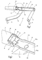
- the in Fig. 1 in perspective, partially illustrated windscreen wiper for a vehicle window has a four-bar linkage 10 and a driven by this in a reciprocating pivotal movement wiper arm 11 which carries at its free end a not shown here wiper blade, which he in his pivotal movement over the vehicle window away leads.
- the four-bar linkage 10 comprises two pivoting levers 12 and 13 each rotationally fixed at one end on an axis 14, 15, of which one axis can be set by means of a wiper motor in a pivoting movement, while the other axis is rotatably received in a support bearing.
- the two pivoting levers 12, 13 are each connected via a joint 16, whose axis of articulation is aligned parallel to the axes 14, 15, with a fastening part representing a coupling.
- the fastening part is designed as a sheet-metal part 17 with a lying in the pivot plane of the coupling, substantially flat back 171 and two thereof approximately at right angles projecting side walls 172.
- the side cheeks 172, 173 located opposite one another on the back 171 on the wiper arm receiving end of the sheet metal part 17 project into protruding ears 18, 19 and form the so-called head region, in which the wiper arm 11 extends to the axes of the joints 16 and the longitudinal axis of the back 171 articulated about right-angled hinge axis is articulated.
- a bore 181, 191 is provided in each of the ears 18, 19, through which a hinge pin 20 is rotatably guided, which in turn is fixed to the wiper arm 11.
- a transverse reinforcement 21 which supports the side cheeks 172, 173 against each other is provided in the transition region of the side cheeks 172, 173 to the ears 18, 19 between the far-upper edges 172a and 173a of the side cheeks 172, 173.
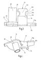
- the transverse reinforcement 21 consists of a first tab 22 which at the upper edge 172a of a side wall 172 about is bent at right angles and extends approximately parallel to the back 171 and from a second tab 23 which is bent at the upper edge 173a of the other side cheek 173 to rest on the first tab 22.
- the second tab 23 carries at its two longitudinal edges downwardly bent claws 24 (FIG. Fig.
- the first tab 22 has lateral recesses 25, in which the claws 24 on the bending of the second tab 23 on the first tab 22 dive.
- the mutually facing boundary edges 251, 252 of the recesses 25 are slightly skewed, in such a way that their clear distance from each other to the bottom of the recess 25 decreases.
- the first tab 22 preferably extends to close to the side wall 173 and may still have an angled portion 26 such that its bent, second tab 23 receiving, cranked portion 221 is lower and thus the superimposed two tabs 22, 23 are flush on the surface ,
- the sheet metal part 17 is punched or cut out with the ears 18, 19 and the tabs 22, 23 with claws 24 and recesses 25 of a metal plate and for forming the side cheeks 172, 173, on the side facing away from the wiper arm 21 end of the sheet metal part 17 in one piece pass over, deep-drawn.
- FIG. 3 shows the first side wall 172 with ear 18 and first tab 22 and the pushed through the bore 181 hinge pin 20 and Fig. 4 the second side wall 173 with the ear 19 and second tab 23 and the pushed through the hole 191 hinge pin 20.
- the second tab 23 is bent from the side wall 173 to the first tab 22 until the lateral claws 24 dip into the recesses 25 in the first tab 22 ( Fig. 4 ). If the second lug 23 rests on the cranked section 221 of the first lug 22, the claws 24 are pressed into the recesses 25 by lateral pressing and are pressed against the boundary edges 251 and 252 of the recesses 25 ( Fig. 2 ).
Landscapes
- Engineering & Computer Science (AREA)
- Mechanical Engineering (AREA)
- Body Structure For Vehicles (AREA)
- Transmission Devices (AREA)
- Bolts, Nuts, And Washers (AREA)
Claims (7)
- Pièce de fixation pour un bras d'essuie-glace (11) d'un essuie-glace de véhicule, comprenant une partie en tôle (17) pouvant être entraînée en un mouvement de pivotement et pouvant être accouplée au bras d'essuie-glace (11), laquelle présente un dos (171) plat situé dans le plan de pivotement et deux parois latérales (172, 173) saillant depuis celui-ci à angle droit, lesquelles se prolongent, à l'extrémité de la partie en tôle (17) du côté recevant le bras d'essuie-glace, dans des oreilles (18, 19) saillant vers le haut, portant un logement pour la liaison articulée du bras d'essuie-glace (21), et comprenant un renforcement transversal (21) réalisé sur la partie en tôle (17), qui supporte l'une contre l'autre les arêtes supérieures (172a, 173a) des parois latérales (172, 173), éloignées du dos, dans la région de transition aux oreilles (18, 19), le renforcement transversal (21) présentant une première patte (22) qui est recourbée au niveau de l'arête supérieure (172a) d'une paroi latérale (172) approximativement parallèlement au dos (171), et une deuxième patte (23), qui est recourbée au niveau de l'arête supérieure (173a) de l'autre paroi latérale (173), caractérisée en ce que la deuxième patte (23) est recourbée jusqu'à venir en appui sur la première patte (22), et en ce que la deuxième patte (23) présente des griffes (24) recourbées depuis leurs deux arêtes longitudinales, qui sont pressées contre la première patte (22).
- Pièce de fixation selon la revendication 1, caractérisée en ce que la première patte (22) présente des évidements latéraux (25) dans lesquels pénètrent les griffes (24) recourbées au niveau de la deuxième patte (23).
- Pièce de fixation selon la revendication 2, caractérisée en ce que les arêtes de limitation tournées l'une vers l'autre (251, 252) des évidements (25) sont biseautées de telle sorte que leur espacement mutuel diminue vers la base (253) de l'évidement (25).
- Pièce de fixation selon l'une quelconque des revendications 1 à 3, caractérisée en ce que la première patte (22) s'étend jusqu'à proximité de la parois latérale opposée (173).
- Pièce de fixation selon l'une quelconque des revendications 1 à 4, caractérisée en ce que les parois latérales (172, 173) réalisées d'une seule pièce avec le dos (171) se prolongent d'une seule pièce l'une dans l'autre au niveau de l'extrémité de la partie en tôle (17) opposée à l'extrémité du côté du recevant le bras d'essuie-glace.
- Pièce de fixation selon la revendication 5, caractérisée en ce que la partie en tôle (17) est estampée avec les oreilles (18, 19), les pattes (22, 23), les évidements (25) et les griffes (24) dans une plaque de tôle et est emboutie profond pour former les parois latérales (172, 173).
- Pièce de fixation selon l'une quelconque des revendications 1 à 6, caractérisée en ce que le logement comprend des alésages (181, 191) en affleurement l'un avec l'autre, pratiqués dans les oreilles (18, 19), pour faire passer un boulon d'articulation (20) fixé dans le bras d'essuie-glace (21).
Applications Claiming Priority (3)
| Application Number | Priority Date | Filing Date | Title |
|---|---|---|---|
| DE10227819A DE10227819A1 (de) | 2002-06-21 | 2002-06-21 | Befestigungsteil für einen Wischerarm eines Fahrzeug-Scheibenwischers |
| DE10227819 | 2002-06-21 | ||
| PCT/DE2003/000252 WO2004000615A1 (fr) | 2002-06-21 | 2003-01-30 | Piece de fixation pour un bras d'essuie-glace de vehicule |
Publications (2)
| Publication Number | Publication Date |
|---|---|
| EP1517818A1 EP1517818A1 (fr) | 2005-03-30 |
| EP1517818B1 true EP1517818B1 (fr) | 2009-08-12 |
Family
ID=29719350
Family Applications (1)
| Application Number | Title | Priority Date | Filing Date |
|---|---|---|---|
| EP03760548A Expired - Lifetime EP1517818B1 (fr) | 2002-06-21 | 2003-01-30 | Piece de fixation pour un bras d'essuie-glace de vehicule |
Country Status (7)
| Country | Link |
|---|---|
| US (1) | US7076829B2 (fr) |
| EP (1) | EP1517818B1 (fr) |
| JP (1) | JP4253637B2 (fr) |
| AT (1) | ATE439280T1 (fr) |
| DE (2) | DE10227819A1 (fr) |
| ES (1) | ES2328346T3 (fr) |
| WO (1) | WO2004000615A1 (fr) |
Families Citing this family (27)
| Publication number | Priority date | Publication date | Assignee | Title |
|---|---|---|---|---|
| DE10039053A1 (de) * | 2000-08-10 | 2002-02-28 | Bosch Gmbh Robert | Befestigungsteil für einen Scheibenwischer |
| US8144724B2 (en) * | 2005-06-30 | 2012-03-27 | Qualcomm Incorporated | Apparatus and method for resolving request collision in a high bandwidth wireless network |
| JP5369730B2 (ja) * | 2009-02-04 | 2013-12-18 | トヨタ車体株式会社 | ワイパ装置 |
| USD706200S1 (en) | 2010-09-22 | 2014-06-03 | Pylon Manufacturing Corporation | Windshield wiper cover |
| US9174609B2 (en) | 2011-04-21 | 2015-11-03 | Pylon Manufacturing Corp. | Wiper blade with cover |
| US9457768B2 (en) | 2011-04-21 | 2016-10-04 | Pylon Manufacturing Corp. | Vortex damping wiper blade |
| US9174611B2 (en) | 2011-07-28 | 2015-11-03 | Pylon Manufacturing Corp. | Windshield wiper adapter, connector and assembly |
| US8806700B2 (en) | 2011-07-29 | 2014-08-19 | Pylon Manufacturing Corporation | Wiper blade connector |
| CA2843637C (fr) | 2011-07-29 | 2018-12-11 | Pylon Manufacturing Corp. | Connecteur d'essuie-glace |
| US9108595B2 (en) | 2011-07-29 | 2015-08-18 | Pylon Manufacturing Corporation | Windshield wiper connector |
| US10723322B2 (en) | 2012-02-24 | 2020-07-28 | Pylon Manufacturing Corp. | Wiper blade with cover |
| US20130219649A1 (en) | 2012-02-24 | 2013-08-29 | Pylon Manufacturing Corp. | Wiper blade |
| MX364943B (es) | 2012-02-24 | 2019-05-14 | Pylon Mfg Corp | Escobilla limpiaparabrisas. |
| US10829092B2 (en) | 2012-09-24 | 2020-11-10 | Pylon Manufacturing Corp. | Wiper blade with modular mounting base |
| US10166951B2 (en) | 2013-03-15 | 2019-01-01 | Pylon Manufacturing Corp. | Windshield wiper connector |
| US9505380B2 (en) | 2014-03-07 | 2016-11-29 | Pylon Manufacturing Corp. | Windshield wiper connector and assembly |
| US9561780B2 (en) * | 2014-07-21 | 2017-02-07 | Ford Global Technologies, Llc | Vehicle window wiper assembly with curvilinear guide rail |
| USD777079S1 (en) | 2014-10-03 | 2017-01-24 | Pylon Manufacturing Corp. | Wiper blade frame |
| USD787308S1 (en) | 2014-10-03 | 2017-05-23 | Pylon Manufacturing Corp. | Wiper blade package |
| DE102014227030A1 (de) * | 2014-12-30 | 2016-06-30 | Robert Bosch Gmbh | Wischarm für eine Scheibenwischvorrichtung in einem Fahrzeug |
| WO2017075066A1 (fr) | 2015-10-26 | 2017-05-04 | Pylon Manufacturing Corp. | Balai d'essuie-glace |
| US11040705B2 (en) | 2016-05-19 | 2021-06-22 | Pylon Manufacturing Corp. | Windshield wiper connector |
| WO2017201473A1 (fr) | 2016-05-19 | 2017-11-23 | Pylon Manufacturing Corp. | Balai d'essuie-glace |
| CN109715449A (zh) | 2016-05-19 | 2019-05-03 | 电缆塔制造有限公司 | 挡风玻璃雨刮器连接器 |
| AU2017267978A1 (en) | 2016-05-19 | 2018-11-22 | Pylon Manufacturing Corp. | Windshield wiper connector |
| WO2017201485A1 (fr) | 2016-05-19 | 2017-11-23 | Pylon Manufacturing Corp. | Connecteur d'essuie-glace |
| DE102017119223A1 (de) * | 2017-08-23 | 2019-02-28 | Valeo Wischersysteme Gmbh | Wischarmeinrichtung für Kraftfahrzeuge |
Family Cites Families (12)
| Publication number | Priority date | Publication date | Assignee | Title |
|---|---|---|---|---|
| GB438419A (en) | 1934-05-23 | 1935-11-15 | William Casson | Improvements in or relating to phase shifters |
| GB838419A (en) * | 1955-07-13 | 1960-06-22 | Trico Products Corp | Improvements in or relating to windscreen wiper arms |
| US3122770A (en) * | 1961-01-12 | 1964-03-03 | Anderson Co | Arm extension adjustor |
| US3176336A (en) * | 1963-08-12 | 1965-04-06 | Trico Products Corp | Wiper arm |
| FR2524407A1 (fr) * | 1982-04-02 | 1983-10-07 | Marchal Equip Auto | Tete d'assemblage matricee d'un element d'essuie-glace, son procede de fabrication et element d'essuie-glace la comportant |
| FR2693693B1 (fr) | 1992-07-15 | 1994-08-19 | Valeo Systemes Dessuyage | Bras d'essuie-glace. |
| US5652994A (en) * | 1993-08-11 | 1997-08-05 | Swf Auto-Electric Gmbh | Wiper arm especially for cleaning windshields of motor vehicles |
| GB9606148D0 (en) * | 1996-03-23 | 1996-05-29 | Trico Ltd | Improvement relating to windscreen wipers heads |
| GB9606149D0 (en) * | 1996-03-23 | 1996-05-29 | Trico Ltd | Improvements relating to bearing mountings |
| DE19735301A1 (de) * | 1997-08-14 | 1999-02-18 | Bosch Gmbh Robert | Wischarm |
| DE10020004A1 (de) * | 2000-04-22 | 2001-11-08 | Bosch Gmbh Robert | Gelenkteil für Scheibenwischer |
| DE10035462A1 (de) * | 2000-07-21 | 2002-02-07 | Bosch Gmbh Robert | Wischarm |
-
2002
- 2002-06-21 DE DE10227819A patent/DE10227819A1/de not_active Withdrawn
-
2003
- 2003-01-30 EP EP03760548A patent/EP1517818B1/fr not_active Expired - Lifetime
- 2003-01-30 US US10/475,384 patent/US7076829B2/en not_active Expired - Lifetime
- 2003-01-30 ES ES03760548T patent/ES2328346T3/es not_active Expired - Lifetime
- 2003-01-30 DE DE50311811T patent/DE50311811D1/de not_active Expired - Lifetime
- 2003-01-30 WO PCT/DE2003/000252 patent/WO2004000615A1/fr not_active Ceased
- 2003-01-30 JP JP2004514532A patent/JP4253637B2/ja not_active Expired - Fee Related
- 2003-01-30 AT AT03760548T patent/ATE439280T1/de not_active IP Right Cessation
Also Published As
| Publication number | Publication date |
|---|---|
| DE10227819A1 (de) | 2004-01-08 |
| JP4253637B2 (ja) | 2009-04-15 |
| JP2005529792A (ja) | 2005-10-06 |
| ATE439280T1 (de) | 2009-08-15 |
| WO2004000615A1 (fr) | 2003-12-31 |
| US20040216261A1 (en) | 2004-11-04 |
| ES2328346T3 (es) | 2009-11-12 |
| DE50311811D1 (de) | 2009-09-24 |
| EP1517818A1 (fr) | 2005-03-30 |
| US7076829B2 (en) | 2006-07-18 |
Similar Documents
| Publication | Publication Date | Title |
|---|---|---|
| EP1517818B1 (fr) | Piece de fixation pour un bras d'essuie-glace de vehicule | |
| EP1940660B1 (fr) | Bras d'essuie-glace | |
| EP1868860B1 (fr) | Dispositif pour relier de façon articulee un balai d'essuie-glace a un bras d'essuie-glace | |
| EP2321160B1 (fr) | Dispositif de liaison articulée entre un balai d essuie-glace et un bras d essuie-glace | |
| EP1363816B1 (fr) | Bras d'essuie-glace pourvu d'une raclette reliee de maniere articulee | |
| EP2099660B1 (fr) | Balai d'essuie-glace | |
| EP2331372B1 (fr) | Raclette d'essuie-glace et assemblage realise entre un bras et une raclette d'un essuie-glace | |
| EP1071591A1 (fr) | Dispositif pour raccorder de maniere articulee a un bras d'essuie-glace une raclette d'essuie-glace destinee a des vitres de vehicules automobiles | |
| WO2002066300A2 (fr) | Systeme d"essuie-glace, destine en particulier a des vehicules automobiles | |
| EP1485279B1 (fr) | Dispositif con u pour guider lateralement un balai d'essuie-glace | |
| DE2919960C2 (fr) | ||
| DE19501211A1 (de) | Wischarm für eine hubgesteuerte Scheibenwischvorrichtung | |
| EP1575813B1 (fr) | Ensemble bras d'essuie-glace comportant un bras d'essuie-glace et une raclette d'essuie-glace | |
| DE2447640A1 (de) | Wischblatt fuer scheibenwischer von kraftfahrzeugen | |
| EP1761421B1 (fr) | Articulation entre un bras d'essuyage et un support de bras d'essuyage et bras d'essuie-glace equipe d'une telle articulation | |
| EP0408712A1 (fr) | Essuie-glace. | |
| DE4140960A1 (de) | Wischarm, insbesondere zur reinigung von scheiben an kraftfahrzeugen | |
| DE3510954A1 (de) | Wischeranlage fuer kraftfahrzeuge | |
| EP0717688A1 (fr) | Bras de monture d'essuie-glace | |
| DE102004003802A1 (de) | Scheibenwischeranlage für Fahrzeuge, insbesondere Straßenfahrzeuge | |
| EP1968826B1 (fr) | Pièce de fixation avec rigidité accrue à la torsion | |
| EP1375274A2 (fr) | Bras pour essuie-glace de véhicule |
Legal Events
| Date | Code | Title | Description |
|---|---|---|---|
| PUAI | Public reference made under article 153(3) epc to a published international application that has entered the european phase |
Free format text: ORIGINAL CODE: 0009012 |
|
| 17P | Request for examination filed |
Effective date: 20050121 |
|
| AK | Designated contracting states |
Kind code of ref document: A1 Designated state(s): AT BE BG CH CY CZ DE DK EE ES FI FR GB GR HU IE IT LI LU MC NL PT SE SI SK TR |
|
| 17Q | First examination report despatched |
Effective date: 20070817 |
|
| GRAP | Despatch of communication of intention to grant a patent |
Free format text: ORIGINAL CODE: EPIDOSNIGR1 |
|
| GRAS | Grant fee paid |
Free format text: ORIGINAL CODE: EPIDOSNIGR3 |
|
| GRAA | (expected) grant |
Free format text: ORIGINAL CODE: 0009210 |
|
| AK | Designated contracting states |
Kind code of ref document: B1 Designated state(s): AT BE BG CH CY CZ DE DK EE ES FI FR GB GR HU IE IT LI LU MC NL PT SE SI SK TR |
|
| REG | Reference to a national code |
Ref country code: GB Ref legal event code: FG4D Free format text: NOT ENGLISH |
|
| REG | Reference to a national code |
Ref country code: CH Ref legal event code: EP |
|
| REG | Reference to a national code |
Ref country code: IE Ref legal event code: FG4D |
|
| REF | Corresponds to: |
Ref document number: 50311811 Country of ref document: DE Date of ref document: 20090924 Kind code of ref document: P |
|
| REG | Reference to a national code |
Ref country code: ES Ref legal event code: FG2A Ref document number: 2328346 Country of ref document: ES Kind code of ref document: T3 |
|
| PG25 | Lapsed in a contracting state [announced via postgrant information from national office to epo] |
Ref country code: FI Free format text: LAPSE BECAUSE OF FAILURE TO SUBMIT A TRANSLATION OF THE DESCRIPTION OR TO PAY THE FEE WITHIN THE PRESCRIBED TIME-LIMIT Effective date: 20090812 Ref country code: SE Free format text: LAPSE BECAUSE OF FAILURE TO SUBMIT A TRANSLATION OF THE DESCRIPTION OR TO PAY THE FEE WITHIN THE PRESCRIBED TIME-LIMIT Effective date: 20090812 |
|
| NLV1 | Nl: lapsed or annulled due to failure to fulfill the requirements of art. 29p and 29m of the patents act | ||
| PG25 | Lapsed in a contracting state [announced via postgrant information from national office to epo] |
Ref country code: SI Free format text: LAPSE BECAUSE OF FAILURE TO SUBMIT A TRANSLATION OF THE DESCRIPTION OR TO PAY THE FEE WITHIN THE PRESCRIBED TIME-LIMIT Effective date: 20090812 Ref country code: NL Free format text: LAPSE BECAUSE OF FAILURE TO SUBMIT A TRANSLATION OF THE DESCRIPTION OR TO PAY THE FEE WITHIN THE PRESCRIBED TIME-LIMIT Effective date: 20090812 |
|
| REG | Reference to a national code |
Ref country code: IE Ref legal event code: FD4D |
|
| PG25 | Lapsed in a contracting state [announced via postgrant information from national office to epo] |
Ref country code: PT Free format text: LAPSE BECAUSE OF FAILURE TO SUBMIT A TRANSLATION OF THE DESCRIPTION OR TO PAY THE FEE WITHIN THE PRESCRIBED TIME-LIMIT Effective date: 20091212 Ref country code: BG Free format text: LAPSE BECAUSE OF FAILURE TO SUBMIT A TRANSLATION OF THE DESCRIPTION OR TO PAY THE FEE WITHIN THE PRESCRIBED TIME-LIMIT Effective date: 20091112 |
|
| PG25 | Lapsed in a contracting state [announced via postgrant information from national office to epo] |
Ref country code: IE Free format text: LAPSE BECAUSE OF FAILURE TO SUBMIT A TRANSLATION OF THE DESCRIPTION OR TO PAY THE FEE WITHIN THE PRESCRIBED TIME-LIMIT Effective date: 20090812 Ref country code: EE Free format text: LAPSE BECAUSE OF FAILURE TO SUBMIT A TRANSLATION OF THE DESCRIPTION OR TO PAY THE FEE WITHIN THE PRESCRIBED TIME-LIMIT Effective date: 20090812 Ref country code: DK Free format text: LAPSE BECAUSE OF FAILURE TO SUBMIT A TRANSLATION OF THE DESCRIPTION OR TO PAY THE FEE WITHIN THE PRESCRIBED TIME-LIMIT Effective date: 20090812 |
|
| PG25 | Lapsed in a contracting state [announced via postgrant information from national office to epo] |
Ref country code: SK Free format text: LAPSE BECAUSE OF FAILURE TO SUBMIT A TRANSLATION OF THE DESCRIPTION OR TO PAY THE FEE WITHIN THE PRESCRIBED TIME-LIMIT Effective date: 20090812 |
|
| PLBE | No opposition filed within time limit |
Free format text: ORIGINAL CODE: 0009261 |
|
| STAA | Information on the status of an ep patent application or granted ep patent |
Free format text: STATUS: NO OPPOSITION FILED WITHIN TIME LIMIT |
|
| 26N | No opposition filed |
Effective date: 20100517 |
|
| BERE | Be: lapsed |
Owner name: ROBERT BOSCH G.M.B.H. Effective date: 20100131 |
|
| PG25 | Lapsed in a contracting state [announced via postgrant information from national office to epo] |
Ref country code: MC Free format text: LAPSE BECAUSE OF NON-PAYMENT OF DUE FEES Effective date: 20100131 |
|
| REG | Reference to a national code |
Ref country code: CH Ref legal event code: PL |
|
| PG25 | Lapsed in a contracting state [announced via postgrant information from national office to epo] |
Ref country code: GR Free format text: LAPSE BECAUSE OF FAILURE TO SUBMIT A TRANSLATION OF THE DESCRIPTION OR TO PAY THE FEE WITHIN THE PRESCRIBED TIME-LIMIT Effective date: 20091113 Ref country code: CH Free format text: LAPSE BECAUSE OF NON-PAYMENT OF DUE FEES Effective date: 20100131 Ref country code: LI Free format text: LAPSE BECAUSE OF NON-PAYMENT OF DUE FEES Effective date: 20100131 |
|
| PG25 | Lapsed in a contracting state [announced via postgrant information from national office to epo] |
Ref country code: BE Free format text: LAPSE BECAUSE OF NON-PAYMENT OF DUE FEES Effective date: 20100131 |
|
| PG25 | Lapsed in a contracting state [announced via postgrant information from national office to epo] |
Ref country code: AT Free format text: LAPSE BECAUSE OF NON-PAYMENT OF DUE FEES Effective date: 20100130 |
|
| PGFP | Annual fee paid to national office [announced via postgrant information from national office to epo] |
Ref country code: IT Payment date: 20120126 Year of fee payment: 10 |
|
| PG25 | Lapsed in a contracting state [announced via postgrant information from national office to epo] |
Ref country code: CY Free format text: LAPSE BECAUSE OF FAILURE TO SUBMIT A TRANSLATION OF THE DESCRIPTION OR TO PAY THE FEE WITHIN THE PRESCRIBED TIME-LIMIT Effective date: 20090812 |
|
| PG25 | Lapsed in a contracting state [announced via postgrant information from national office to epo] |
Ref country code: LU Free format text: LAPSE BECAUSE OF NON-PAYMENT OF DUE FEES Effective date: 20100130 Ref country code: HU Free format text: LAPSE BECAUSE OF FAILURE TO SUBMIT A TRANSLATION OF THE DESCRIPTION OR TO PAY THE FEE WITHIN THE PRESCRIBED TIME-LIMIT Effective date: 20100213 |
|
| PG25 | Lapsed in a contracting state [announced via postgrant information from national office to epo] |
Ref country code: TR Free format text: LAPSE BECAUSE OF FAILURE TO SUBMIT A TRANSLATION OF THE DESCRIPTION OR TO PAY THE FEE WITHIN THE PRESCRIBED TIME-LIMIT Effective date: 20090812 |
|
| PGFP | Annual fee paid to national office [announced via postgrant information from national office to epo] |
Ref country code: FR Payment date: 20130207 Year of fee payment: 11 Ref country code: GB Payment date: 20130122 Year of fee payment: 11 Ref country code: CZ Payment date: 20130121 Year of fee payment: 11 Ref country code: ES Payment date: 20130122 Year of fee payment: 11 |
|
| GBPC | Gb: european patent ceased through non-payment of renewal fee |
Effective date: 20140130 |
|
| PG25 | Lapsed in a contracting state [announced via postgrant information from national office to epo] |
Ref country code: CZ Free format text: LAPSE BECAUSE OF NON-PAYMENT OF DUE FEES Effective date: 20140130 |
|
| REG | Reference to a national code |
Ref country code: FR Ref legal event code: ST Effective date: 20140930 |
|
| PG25 | Lapsed in a contracting state [announced via postgrant information from national office to epo] |
Ref country code: FR Free format text: LAPSE BECAUSE OF NON-PAYMENT OF DUE FEES Effective date: 20140131 Ref country code: GB Free format text: LAPSE BECAUSE OF NON-PAYMENT OF DUE FEES Effective date: 20140130 |
|
| REG | Reference to a national code |
Ref country code: ES Ref legal event code: FD2A Effective date: 20150326 |
|
| PG25 | Lapsed in a contracting state [announced via postgrant information from national office to epo] |
Ref country code: ES Free format text: LAPSE BECAUSE OF NON-PAYMENT OF DUE FEES Effective date: 20140131 |
|
| PG25 | Lapsed in a contracting state [announced via postgrant information from national office to epo] |
Ref country code: IT Free format text: LAPSE BECAUSE OF NON-PAYMENT OF DUE FEES Effective date: 20140130 |
|
| PGFP | Annual fee paid to national office [announced via postgrant information from national office to epo] |
Ref country code: DE Payment date: 20220324 Year of fee payment: 20 |
|
| REG | Reference to a national code |
Ref country code: DE Ref legal event code: R071 Ref document number: 50311811 Country of ref document: DE |