EP1575813B1 - Ensemble bras d'essuie-glace comportant un bras d'essuie-glace et une raclette d'essuie-glace - Google Patents
Ensemble bras d'essuie-glace comportant un bras d'essuie-glace et une raclette d'essuie-glace Download PDFInfo
- Publication number
- EP1575813B1 EP1575813B1 EP03813523A EP03813523A EP1575813B1 EP 1575813 B1 EP1575813 B1 EP 1575813B1 EP 03813523 A EP03813523 A EP 03813523A EP 03813523 A EP03813523 A EP 03813523A EP 1575813 B1 EP1575813 B1 EP 1575813B1
- Authority
- EP
- European Patent Office
- Prior art keywords
- wiper
- wiper blade
- arm
- blade
- lever
- Prior art date
- Legal status (The legal status is an assumption and is not a legal conclusion. Google has not performed a legal analysis and makes no representation as to the accuracy of the status listed.)
- Expired - Lifetime
Links
- 238000005452 bending Methods 0.000 description 32
- 238000000034 method Methods 0.000 description 22
- 229910000831 Steel Inorganic materials 0.000 description 8
- 239000010959 steel Substances 0.000 description 8
- 238000004519 manufacturing process Methods 0.000 description 6
- 239000000463 material Substances 0.000 description 5
- 238000004080 punching Methods 0.000 description 4
- XEEYBQQBJWHFJM-UHFFFAOYSA-N Iron Chemical compound [Fe] XEEYBQQBJWHFJM-UHFFFAOYSA-N 0.000 description 2
- 230000008878 coupling Effects 0.000 description 2
- 238000010168 coupling process Methods 0.000 description 2
- 238000005859 coupling reaction Methods 0.000 description 2
- 230000005489 elastic deformation Effects 0.000 description 2
- 239000002184 metal Substances 0.000 description 2
- 229910052751 metal Inorganic materials 0.000 description 2
- 229920002430 Fibre-reinforced plastic Polymers 0.000 description 1
- 239000000853 adhesive Substances 0.000 description 1
- 230000001070 adhesive effect Effects 0.000 description 1
- 239000011324 bead Substances 0.000 description 1
- 238000004140 cleaning Methods 0.000 description 1
- 238000010276 construction Methods 0.000 description 1
- 238000009826 distribution Methods 0.000 description 1
- 239000011151 fibre-reinforced plastic Substances 0.000 description 1
- 229910052742 iron Inorganic materials 0.000 description 1
- 238000010409 ironing Methods 0.000 description 1
- 239000004033 plastic Substances 0.000 description 1
- 229920003023 plastic Polymers 0.000 description 1
- 230000002441 reversible effect Effects 0.000 description 1
Images


Classifications
-
- B—PERFORMING OPERATIONS; TRANSPORTING
- B60—VEHICLES IN GENERAL
- B60S—SERVICING, CLEANING, REPAIRING, SUPPORTING, LIFTING, OR MANOEUVRING OF VEHICLES, NOT OTHERWISE PROVIDED FOR
- B60S1/00—Cleaning of vehicles
- B60S1/02—Cleaning windscreens, windows or optical devices
- B60S1/04—Wipers or the like, e.g. scrapers
- B60S1/32—Wipers or the like, e.g. scrapers characterised by constructional features of wiper blade arms or blades
- B60S1/40—Connections between blades and arms
- B60S1/42—Connections between blades and arms resilient
-
- B—PERFORMING OPERATIONS; TRANSPORTING
- B60—VEHICLES IN GENERAL
- B60S—SERVICING, CLEANING, REPAIRING, SUPPORTING, LIFTING, OR MANOEUVRING OF VEHICLES, NOT OTHERWISE PROVIDED FOR
- B60S1/00—Cleaning of vehicles
- B60S1/02—Cleaning windscreens, windows or optical devices
- B60S1/04—Wipers or the like, e.g. scrapers
- B60S1/32—Wipers or the like, e.g. scrapers characterised by constructional features of wiper blade arms or blades
- B60S1/34—Wiper arms; Mountings therefor
- B60S1/3425—Constructional aspects of the arm
- B60S1/3427—Arm piece, link piece and mounting head formed as one element
-
- B—PERFORMING OPERATIONS; TRANSPORTING
- B60—VEHICLES IN GENERAL
- B60S—SERVICING, CLEANING, REPAIRING, SUPPORTING, LIFTING, OR MANOEUVRING OF VEHICLES, NOT OTHERWISE PROVIDED FOR
- B60S1/00—Cleaning of vehicles
- B60S1/02—Cleaning windscreens, windows or optical devices
- B60S1/04—Wipers or the like, e.g. scrapers
- B60S1/32—Wipers or the like, e.g. scrapers characterised by constructional features of wiper blade arms or blades
- B60S1/38—Wiper blades
- B60S1/3848—Flat-type wiper blade, i.e. without harness
- B60S1/3874—Flat-type wiper blade, i.e. without harness with a reinforcing vertebra
- B60S1/3875—Flat-type wiper blade, i.e. without harness with a reinforcing vertebra rectangular section
-
- B—PERFORMING OPERATIONS; TRANSPORTING
- B60—VEHICLES IN GENERAL
- B60S—SERVICING, CLEANING, REPAIRING, SUPPORTING, LIFTING, OR MANOEUVRING OF VEHICLES, NOT OTHERWISE PROVIDED FOR
- B60S1/00—Cleaning of vehicles
- B60S1/02—Cleaning windscreens, windows or optical devices
- B60S1/04—Wipers or the like, e.g. scrapers
- B60S1/32—Wipers or the like, e.g. scrapers characterised by constructional features of wiper blade arms or blades
- B60S1/40—Connections between blades and arms
-
- B—PERFORMING OPERATIONS; TRANSPORTING
- B60—VEHICLES IN GENERAL
- B60S—SERVICING, CLEANING, REPAIRING, SUPPORTING, LIFTING, OR MANOEUVRING OF VEHICLES, NOT OTHERWISE PROVIDED FOR
- B60S1/00—Cleaning of vehicles
- B60S1/02—Cleaning windscreens, windows or optical devices
- B60S1/04—Wipers or the like, e.g. scrapers
- B60S1/32—Wipers or the like, e.g. scrapers characterised by constructional features of wiper blade arms or blades
- B60S1/38—Wiper blades
- B60S2001/3812—Means of supporting or holding the squeegee or blade rubber
- B60S2001/3825—Means of supporting or holding the squeegee or blade rubber the squeegee mounted directly to or in wiper blade arm
Definitions
- the invention is based on a wiper lever according to the preamble of claim 1.
- the wiper blade has a resilient, arcuately curved wiper strip carrier, to which an elongate wiper strip is fastened, whose wiper lip extends on a concave side of the wiper strip carrier along the same. Furthermore, the wiper blade comprises a wind deflector arranged on a convex side of the wiper carrier.
- the rod-shaped wiper arm is connected to the wiper blade via a joint.
- the wiper blade has in its longitudinal middle section a bearing point formed by a transverse bore for a hinge pin fastened to the wiper arm.
- the invention is based on a wiper lever with a wiper arm and a wiper blade.
- the wiper arm and the wiper blade are connected to each other without joints. It can achieve a particularly simple and flat design and construction, in particular, the number of components, assembly costs and costs can be reduced.
- the wiper lever can be guided into an extended parking position in a particularly narrow recess, for example under a hood or in a specially shaped A-pillar of a motor vehicle.
- wear-prone and error-prone components, in particular bearing components can be at least largely reduced.
- the wiper arm and the wiper blade are connected via at least one spring-elastic connecting part, compensation for a stroke movement or a relative movement between the wiper arm and the wiper blade during operation can advantageously be ensured.
- the wiper arm and the wiper blade are connected to one another via a substantially rigid connecting part.
- a compensation of relative movements between the wiper arm and the wiper blade could be achieved by the wiper arm and / or by the wiper blade itself.
- the wiper blade has a spring-elastic wiper strip carrier element connected to the wiper arm in a joint-free manner, on the concave side of which a wiper lip of a wiper strip extends in the mounted state.
- a wiper lip of a wiper strip extends in the mounted state.
- the wiper arm has at least one resilient carrier element. On a joint in the wiper arm can be omitted and it can save additional components and the overall height of the wiper lever can be further reduced. Furthermore, in combination with a non-iron wiper blade, the wiper arm and the wiper blade are advantageously produced inexpensively on at least substantially the same production machines.
- the connecting part may advantageously be made in one piece with at least one resilient support element, such as a wiper support element and / or a support element of the wiper arm, whereby additional components, assembly costs and costs can be saved.
- at least one resilient support element such as a wiper support element and / or a support element of the wiper arm
- the wiper arm and the wiper blade are at least partially made in one piece, in turn additional components can be saved and a particularly cost-effective production can be achieved, in particular if the wiper arm and the wiper blade are formed from a common stamped and bent part. Furthermore, a particularly harmonic bending line of the wiper lever can be achieved and weak points can be easily avoided.
- the wiper blade is connected to the wiper arm via its outer wiper blade end or has a contact force introduction point at its outer wiper blade end. It can be achieved a long wiper arm and in particular in an embodiment of the wiper arm with a resilient support member an advantageously long length can be achieved over which compensates a relative movement between the wiper arm and the wiper blade and a large relative movement of the wiper blade substantially perpendicular to the windshield can be made possible for example, for comfortable cleaning of the windshield. Furthermore, a particularly small inner circle of the wiper blade or a small distance of an inner wiper blade end can be achieved to a drive shaft, via which the wiper lever is driven.
- a vibration-insensitive wiper lever can be achieved and a design with a low use of material can be achieved.
- the wiper blade is connected to the wiper arm over an area between its wiper blade ends and in particular via its longitudinal middle section or if the wiper blade has a contact force introduction point in its longitudinal middle section, a particularly advantageous, in particular at least substantially symmetrical, force distribution on the wiper blade can be achieved.
- connection points or contact force introduction points namely at the outer wiper blade end, at the inner wiper blade end and in a region between the wiper blade ends, can also be combined as desired.
- the wiper arm is connected to the wiper blade via at least one crosspiece, whereby an advantageous distance between the wiper blade and the wiper arm can be achieved easily, with little use of material, via which relative movements between the two components can be compensated, for example via an elastic deformation.
- an elastic deformation can be adjusted by the crosspiece advantageously a resulting during operation wiping field.
- the use of a crosspiece is particularly suitable for connection of the wiper blade to its inner wiper blade end or in its longitudinal central portion with the wiper arm, but can also be used for connection of the wiper blade at its outer wiper blade end with the wiper arm.
- an advantageous distance between the wiper blade and the wiper arm can be achieved, via which, in turn, compensation for movement can be realized by connecting the wiper arm and the wiper blade via an at least one deflection at an angle greater than 90 °.
- the wiper blade has at least one slot-shaped recess for receiving a wiper strip, proven wiper strips can be easily mounted on the wiper blade. In principle, however, the use of glued wiper strips or designed as a hollow profile wiper strips is conceivable.
- the wiper arm and the wiper blade are advantageously formed from a resilient steel sheet, which can be used on proven for ironless wiper blades production equipment.
- a resilient steel sheet which can be used on proven for ironless wiper blades production equipment.
- fiber-reinforced plastics etc.
- beads, U-profiles, etc. for example by integrating these onto the wiper arm or onto the wiper blade or by fastening additional components.
- a wind deflector on the wiper blade and / or on the wiper arm, which can be formed by an additional component, for example by a plastic component, or at least partially integrally formed on the wiper blade and / or on the wiper arm, for example by integrally is formed on a stamped and bent sheet metal part.
- the wiper lever according to the invention can be performed as a full wiper lever applied both for a front and for a rear window or can be designed as a so-called transport wiper lever, which is replaced by a separate wiper before delivery to an end customer.
- the wiper arm 10 a, the connecting part 16 a and the wiper blade 12 a are made in one piece and are formed by a common, elongated punched and bent part made of a resilient steel sheet.
- the components in the finished state by various, the skilled person may appear reasonable connected cohesive, forinschlüssige and / or non-positive connections, for example by a rivet, a clamp connection, a screw, a welded connection and / or an adhesive bond, etc.
- essentially the area is regarded as a wiper blade 12a, in which a wiper strip extends in the fully assembled state.
- the wiper blade 12a has a spring-elastic, arcuate wiper strip carrier element 18a which is connected to the wiper arm 10a in a joint-free manner and on the concave side of which a wiper lip of a wiper strip extends in the assembled state ( Fig. 3 ).
- the wiper carrier element 18a has a slot-shaped, extending in the longitudinal direction Recess 14a for receiving the wiper strip.
- the channel 14a is made open towards a free end of the wiper carrier element 18a.
- the wiper strip can advantageously be introduced via the free end of the wiper strip carrier element 18a. However, the recess 14a could also be designed to be closed at the free end.
- the wiper arm 10a has a resilient support element 20a, which has at its free end a recess 24a for coupling to a drive shaft.
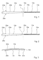
- the wiper lever is substantially flat and has starting from the recess 24a shortly after the same in the direction of the wiper blade 12a two transversely to the longitudinal direction extending, integrally formed on the wiper arm 10a tabs 26a, 28a ( Fig. 1 ).
- the tabs 26a, 28a are bent by 90 ° in the direction of an underside of the wiper lever ( Fig. 2 ).
- the free end of the wiper blade 12a is bent in the direction of the free end of the wiper arm 10a, by about 180 ° about a perpendicular to the longitudinal extension and parallel to a bottom of the wiper lever bending axis 30a in the region of the connecting part 16a, in the bent state considered, starting from the recess 24a in the direction wiper blade 12a is arranged shortly after a longitudinal center.
- the wiper arm 10a and the wiper blade 12a are connected to one another ( Fig. 3 ). Furthermore, slight longitudinal curvatures are formed on the wiper arm 10a and on the wiper blade 12a. In addition or as an alternative to the wiper blade 12a, the wiper arm 10a could also be bent around the bending axis 30a. The free end of the wiper blade 12a comes to lie in the region of the tabs 26a, 28a, which form a wiper blade guide. About the wiper blade forming tabs 26a, 28a can be at least reduced without additional components vibrations of the wiper lever and in particular of the wiper blade.
- the wiper blade 12a is connected to the wiper arm 10a via its outer wiper blade end and via the connecting part 16a. In operation, in the region of an outer circle of the wiper blade 12a or is transmitted from the wiper arm 10a via the connecting part 16a and the outer wiper blade end a bearing force on the wiper blade 12a.
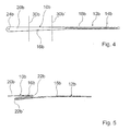
- the wiper lever comprises a wiper arm 10b and a wiper blade 12b, which are connected without hinges via a spring-elastic connecting part 16b.
- the wiper arm 10b, the connecting part 16b and the wiper blade 12b are made in one piece and are formed by a common, elongated stamped and bent part of a resilient steel sheet.
- the wiper lever Before a bending process following a punching process, the wiper lever is essentially flat ( Fig. 4 ).
- the free end of the wiper blade 12b is bent in the direction of the free end of the wiper arm 10b by approximately 180 ° about a first first bending axis 30b in the region perpendicular to the longitudinal extension and parallel to an underside of the wiper lever of the connecting part 16b.
- the free end of the wiper blade 12b opposite to the first bending direction is bent by about 180 ° about a second bending axis 30b 'in the region of the connecting part 16b aligned parallel to the first bending axis 30b and viewed in the bent state, starting from a recess 24b in the wiper arm 10b for articulation thereof to a drive shaft, is arranged in the direction of the wiper blade 12b after the first bending axis 30b.
- the connecting part 16b essentially an S-shaped configuration with two essentially arises 180 ° deflections 22b, 22b ', over which the wiper arm 10b and the wiper blade 12b are connected to each other ( Fig. 5 ).
- the S-shaped configuration results in an advantageous range over which a relative movement between the wiper arm 10b and the wiper blade 12b can be compensated.
- the wiper arm 10b could also be bent about the bending axes 30b, 30b '.
- the wiper blade 12b is connected to the wiper arm 10b via its inner wiper blade end and via the connecting part 16b. In operation, in the region of an inner circle of the wiper blade 12b or is transmitted from the wiper arm 10b via the connecting part 16b and the inner wiper blade end a bearing force on the wiper blade 12b.
- a slot-shaped recess 14b is inserted in a spring-elastic, arcuate wiper strip carrier element 18b of the wiper blade 12b, which slot is closed in the area of the free end of the wiper blade 12b.
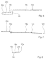
- Fig. 6 to 8 is an alternative wiper lever to that in the 4 and 5 shown.
- the wiper lever has a connecting part 16c formed by a crosspiece, which is aligned transversely to the longitudinal extent of the wiper lever, and over which a wiper arm 10c and a wiper blade 12c of the wiper lever are connected without joints.
- the wiper arm 10 c, the connecting part 16 c and the wiper blade 12 c are made in one piece and are formed by a common, elongated punched and bent part of a resilient steel sheet.
- the wiper blade 12c is connected to the wiper arm 10c via its inner wiper blade end and via the connecting part 16c.
- the connecting part 16c is angled ( FIGS. 7 and 8 ).
- a wiper strip filled out as a hollow profile can be pushed onto a wiper strip support element 18c of the wiper blade 12c which is embodied over the whole surface or without a recess, or a wiper strip can be glued on.
- Fig. 9 to 12 is an alternative wiper lever to that in the Fig. 6 to 8 shown.
- the wiper lever has a connecting part 16d formed by a cross piece, which is aligned transversely to the longitudinal extent of the wiper lever and over which a wiper arm 10d and a wiper blade 12d of the wiper lever are connected without joints.
- the wiper arm 10d, the connecting part 16d and the wiper blade 12d are made in one piece and are formed by a common, elongated punched-bent part made of a resilient steel sheet.
- the wiper lever Before a bending process following a punching process, the wiper lever is essentially flat ( Fig. 9 ).
- the wiper blade 12d In the bending process, the wiper blade 12d is bent in the direction of the wiper arm 10d by approximately 180 ° about a bending axis 30d extending parallel to the longitudinal extension of the wiper blade 12d in the region of the connecting part 16d, so that the wiper arm 10d and the wiper blade 12d are aligned.
- the wiper arm 10d could also be bent around the bending axis 30d.
- the wiper blade 12d is connected to the wiper arm 10d via its inner wiper blade end and via the connecting part 16d. In operation, in the region of an inner circle of the wiper blade 12d or is transmitted from the wiper arm 10d via the connecting part 16d and the inner wiper blade end a bearing force on the wiper blade 12d.
- a slot-shaped recess is formed in a spring-elastic, arcuate wiper support element 18d of the wiper blade 12d 14d introduced, which is designed to be open in the region of the free end of the wiper blade 12d.
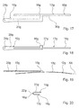
- FIGS. 13 and 14 is an alternative wiper lever to that in the Fig. 1 to 3 shown.
- the wiper lever has connecting parts 16e, 16e 'formed by transverse pieces, which are aligned transversely to the longitudinal extension of the wiper lever, and via which a wiper arm 10e and a wiper blade 12e of the wiper lever are connected without joints.
- the wiper arm 10e, the connecting parts 16e, 16e 'and the wiper blade 12e are made in one piece and are formed by a common, elongate stamped and bent part made of a resilient steel sheet.
- the wiper arm 10e and the wiper blade 12e viewed in the unbent state, have a common longitudinal axis, wherein a wiper blade part is formed by a cut-free part of a sheet metal section which likewise forms the wiper arm 10e.
- the wiper blade 12e is connected to the wiper arm 10e via its longitudinal middle section and via the connecting parts 16e, 16e '. In operation, in the region of a center circle of the wiper blade 12e or is transferred from the wiper arm 10e via the connecting parts 16e, 16e 'and over the longitudinal center portion of the wiper blade 12e a bearing force on the wiper blade 12d.
- a wiper strip designed as a hollow profile can be pushed onto a wiper strip carrier element 18e of the wiper blade 12e that is embodied over the entire surface or without a recess, or a wiper strip can be glued on.
- the wiper strip support element 18e could also be embodied with a slot-shaped opening extending over its length and open toward one end or both ends, into which a wiper strip can be inserted.
- FIGS. 15 and 16 is one of those in the FIGS. 13 and 14 illustrated alternative wiper lever, instead of two connecting parts 16e, 16e 'only one formed by a crosspiece connecting part 16f, via which a wiper arm 10f and a wiper blade 12f are connected without hinges.
- Fig. 17 to 20 is an alternative wiper lever to that in the FIGS. 15 and 16 shown.
- the wiper lever has a connecting part 16g formed by a crosspiece, which is oriented transversely to the longitudinal extent of the wiper lever, and via which a wiper arm 10g and a wiper blade 12g of the wiper lever are connected without joints.
- the wiper arm 10g, the connecting part 16g and the wiper blade 12g are made in one piece and are formed by a common, elongated stamped and bent part of a resilient steel sheet.
- the wiper lever Before a bending process following a punching process, the wiper lever is essentially flat ( Fig. 17 ).
- the wiper blade 12g In the bending process, the wiper blade 12g is bent in the direction of the wiper arm 10g, by about 180 ° about a bending axis 30g extending parallel to the longitudinal extent of the wiper blade 12g in the region of the connecting part 16g, so that the wiper blade 12g and the wiper arm 10g are substantially in alignment.
- the wiper arm 10g In the region of the connecting part 16g, there is essentially a 180 ° deflection 22g, via which the wiper arm 10g and the wiper blade 12g are connected to one another ( FIGS. 18, 19 and 20 ).
- the wiper arm 10g could also be bent around the bending axis 30g.
- the wiper blade 12g is connected to the wiper arm 10g via its longitudinal middle section and via the connecting part 16g. In operation, in the region of a center circle of the wiper blade 12g or is transmitted from the wiper arm 10g via the connecting part 16g and over the longitudinal center portion of the wiper blade 12g a bearing force on the wiper blade 12g.
- a wiper strip designed as a hollow profile can be pushed onto a wiper strip support element 18g of the wiper blade 12g, which is executed over the whole surface or without a recess, or a wiper strip can be glued on.
- the wiper support member 18g could also with a extending over its length, slit-shaped, to a Be executed end or closed at both ends towards recess in which a wiper strip can be inserted.
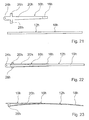
- FIG. 21 to 23 an alternative wiper lever with a wiper arm 10h and a wiper blade 12h is shown in various stages of manufacture, wherein the wiper arm 10h and the wiper blade 12h finished according to the invention are connected joint-free, by a resilient connection part 16h ( Fig. 23 ).
- the wiper arm 10h and the connecting part 16h are made in one piece and are formed by a common, elongated punched-bent part of a resilient steel sheet.
- the wiper arm 10h has at one end a recess 24h for coupling to a drive shaft, while at a second end of the wiper arm 10h, the connecting part 16g is arranged.
- the wiper blade 12h is formed by a stamped and bent part formed separately from the wiper arm 10h and connecting part 16h and has a smaller material thickness than the wiper arm 10h and the connecting part 16h.
- the wiper blade 12h is welded in a manufacturing stage with its longitudinal central portion with the connecting part 16h ( FIGS. 22 and 23 ). Further, in a bending process to the wiper arm 10h molded tabs 26h, 28h are bent by 90 ° in the direction of an underside of the wiper lever, which form a wiper blade guide on the inner circle of the wiper blade 12h.
- the wiper blade 12h is connected to the wiper arm 10h via its longitudinal middle section and via the connecting part 16h. In operation, in the region of a central circle of the wiper blade 12h or is transferred from the wiper arm 10h via the connecting part 16h and over the longitudinal center portion of the wiper blade 12h a bearing force on the wiper blade 12h.
- a wiper strip designed as a hollow profile can be pushed onto a wiper strip carrier element 18h of the wiper blade 12h running over the entire surface or without a recess, or a wiper strip can be glued on.
- the wiper strip carrier element 18h could also be designed with a slot-shaped opening extending over its length and closed at one end or at both ends, into which a wiper strip can be inserted.
Landscapes
- Engineering & Computer Science (AREA)
- Mechanical Engineering (AREA)
- Ink Jet (AREA)
- Pivots And Pivotal Connections (AREA)
- Body Structure For Vehicles (AREA)
Claims (10)
- Ensemble à bras d'essuie-glace comprenant un bras d'essuie-glace 10a- 10h) et une lame d'essuie-glace (12a-12h), le bras étant relié à la lame d'essuie-glace (12a-12h) sans articulation, le bras d'essuie-glace (10a-10g) et la lame d'essuie-glace (12a-12g) étant réalisés au moins partiellement en une seule pièce,
caractérisé en ce que
la lame d'essuie-glace (12a-12h) est reliée entre ses extrémités au bras d'essuie-glace (10e-10h) par au moins un élément transversal élastique comme un ressort à la lame d'essuie-glace (12c-12g). - Ensemble à bras d'essuie-glace selon la revendication 1,
caractérisé en ce que
le bras d'essuie-glace (10a-10h) et la lame d'essuie-glace (12a-12h) sont reliés par au moins une pièce de liaison élastique comme un ressort (16a-16h) . - Ensemble à bras d'essuie-glace selon la revendication 1 ou 2,
caractérisé en ce que
la lame d'essuie-glace (12a-12h) est reliée sans articulation au bras d'essuie-glace (10a-10h) et comporte un élément de support de lame (18a-18h) élastique comme un ressort et à l'état monté, la lèvre de la lame d'essuie-glace s'étend contre le côté concave de cet élément. - Ensemble à bras d'essuie-glace selon l'une des revendications précédèntes,
caractérisé en ce que
le bras d'essuie-glace (10a-10h) comporte au moins un élément de support élastique comme un ressort (20a-20h). - Ensemble à bras d'essuie-glace au moins selon la revendication 2,
caractérisé en ce que
la pièce de liaison (16a-16h) est réalisée en une seule partie avec au moins un élément de support élastique comme un ressort (18a-18g, 20a-20h). - Ensemble à bras d'essuie-glace selon la revendication 5,
caractérisé en ce que
le bras d'essuie-glace (10a-10g) et la lame d'essuie-glace (12a-12g) sont réalisés en une seule pièce emboutie et cintrée. - Ensemble à bras d'essuie-glace selon l'une des revendications précédentes,
caractérisé en ce que
la lame d'essuie-glace (12a) est également reliée par son extrémité extérieure au bras d'essuie-glace (10a). - Ensemble à bras d'essuie-glace selon l'une des revendications précédentes,
caractérisé en ce que
le balai d'essuie-glace (12b-12d) est également relié par son extrémité intérieure au bras d'essuie-glace (12b-12d). - Ensemble à bras d'essuie-glace selon l'une des revendications précédentes,
caractérisé en ce que
le bras d'essuie-glace (10a, 10b, 10d, 10g) et la lame d'essuie-glace (12a, 12b, 12d, 12g) sont reliés par un retour (22a, 22b, 22d, 22g) ayant un angle supérieur à 90°. - Ensemble à bras d'essuie-glace selon l'une des revendications précédentes,
caractérisé en ce que
la lame d'essuie-glace (12a, 12b, 12d) comporte au moins une cavité en forme de fente (14a, 14b, 14d) pour recevoir une lame d'essuie-glace.
Applications Claiming Priority (3)
| Application Number | Priority Date | Filing Date | Title |
|---|---|---|---|
| DE10259479A DE10259479A1 (de) | 2002-12-19 | 2002-12-19 | Wischhebel |
| DE10259479 | 2002-12-19 | ||
| PCT/DE2003/002602 WO2004056626A1 (fr) | 2002-12-19 | 2003-08-04 | Ensemble bras d'essuie-glace comportant un bras d'essuie-glace et une raclette d'essuie-glace |
Publications (2)
| Publication Number | Publication Date |
|---|---|
| EP1575813A1 EP1575813A1 (fr) | 2005-09-21 |
| EP1575813B1 true EP1575813B1 (fr) | 2008-02-27 |
Family
ID=32403951
Family Applications (1)
| Application Number | Title | Priority Date | Filing Date |
|---|---|---|---|
| EP03813523A Expired - Lifetime EP1575813B1 (fr) | 2002-12-19 | 2003-08-04 | Ensemble bras d'essuie-glace comportant un bras d'essuie-glace et une raclette d'essuie-glace |
Country Status (6)
| Country | Link |
|---|---|
| US (1) | US20080052864A1 (fr) |
| EP (1) | EP1575813B1 (fr) |
| CN (1) | CN100408394C (fr) |
| DE (2) | DE10259479A1 (fr) |
| ES (1) | ES2299763T3 (fr) |
| WO (1) | WO2004056626A1 (fr) |
Cited By (1)
| Publication number | Priority date | Publication date | Assignee | Title |
|---|---|---|---|---|
| DE102012112526A1 (de) | 2012-12-18 | 2014-06-18 | Dr. Ing. H.C. F. Porsche Aktiengesellschaft | Wischerhebel eines Kraftfahrzeugscheibenwischers |
Families Citing this family (10)
| Publication number | Priority date | Publication date | Assignee | Title |
|---|---|---|---|---|
| DE102005048344A1 (de) * | 2005-10-10 | 2007-04-12 | Robert Bosch Gmbh | Scheibenwischerarm |
| ITTO20070136A1 (it) | 2007-02-27 | 2008-08-28 | Giovanni Creaco | Tergicristallo per autoveicoli. |
| DE102012210945A1 (de) * | 2012-06-27 | 2014-01-02 | Robert Bosch Gmbh | Wischvorrichtung |
| FR2995850B1 (fr) * | 2012-09-27 | 2015-06-05 | Valeo Systemes Dessuyage | Système d'essuyage d'une vitre, notamment vitre arriere de vehicule automobile |
| DE102014209269A1 (de) * | 2014-05-15 | 2015-11-19 | Volkswagen Aktiengesellschaft | Scheibenwischer |
| DE102014215831B4 (de) * | 2014-08-11 | 2025-01-23 | Robert Bosch Gmbh | Scheibenwischvorrichtung |
| FR3031948A1 (fr) * | 2015-01-22 | 2016-07-29 | Peugeot Citroen Automobiles Sa | Dispositif d’essuyage pour pare-brise de vehicule automobile |
| FR3035049A1 (fr) * | 2015-04-17 | 2016-10-21 | Valeo Systemes Dessuyage | Balai d’essuyage et ensemble d’essuyage comprenant un tel balai |
| FR3055280B1 (fr) * | 2016-08-24 | 2018-08-31 | Valeo Systemes D'essuyage | Ensemble de montage d’un balai d’essuyage sur un arbre d’entrainement |
| FR3106548B1 (fr) * | 2020-01-28 | 2022-10-28 | Valeo Systemes Dessuyage | Essuyage pour petite surface |
Family Cites Families (7)
| Publication number | Priority date | Publication date | Assignee | Title |
|---|---|---|---|---|
| FR1217680A (fr) * | 1958-10-01 | 1960-05-05 | Balai d'essuie-glace pour pare-brise plats ou bombés de véhicules | |
| DE2364622A1 (de) * | 1972-12-28 | 1974-07-04 | British Aluminium Co Ltd | Scheibenwischer |
| FR2551709B1 (fr) * | 1983-09-13 | 1987-06-12 | Champion Spark Plug Europ | Systeme d'essuie-glace pour vehicules a moteur |
| DE19856300A1 (de) | 1998-12-07 | 2000-06-08 | Bosch Gmbh Robert | Wischblatt für Scheiben von Kraftfahrzeugen |
| WO2002012033A1 (fr) * | 2000-08-07 | 2002-02-14 | Valeo Auto-Electric Wischer Und Motoren Gmbh | Systeme d'essuie-glace, notamment pour automobile |
| DE10108200A1 (de) * | 2001-02-21 | 2002-08-22 | Bosch Gmbh Robert | Wischvorrichtung insbesondere für Scheiben von Kraftfahrzeugen |
| DE10109088B4 (de) * | 2001-02-24 | 2016-10-06 | Valeo Auto-Electric Wischer Und Motoren Gmbh | Scheibenwischerarm-Wischblatt-Anordnung |
-
2002
- 2002-12-19 DE DE10259479A patent/DE10259479A1/de not_active Withdrawn
-
2003
- 2003-08-04 ES ES03813523T patent/ES2299763T3/es not_active Expired - Lifetime
- 2003-08-04 CN CNB038113813A patent/CN100408394C/zh not_active Expired - Fee Related
- 2003-08-04 EP EP03813523A patent/EP1575813B1/fr not_active Expired - Lifetime
- 2003-08-04 WO PCT/DE2003/002602 patent/WO2004056626A1/fr not_active Ceased
- 2003-08-04 US US10/539,990 patent/US20080052864A1/en not_active Abandoned
- 2003-08-04 DE DE50309278T patent/DE50309278D1/de not_active Expired - Lifetime
Cited By (2)
| Publication number | Priority date | Publication date | Assignee | Title |
|---|---|---|---|---|
| DE102012112526A1 (de) | 2012-12-18 | 2014-06-18 | Dr. Ing. H.C. F. Porsche Aktiengesellschaft | Wischerhebel eines Kraftfahrzeugscheibenwischers |
| WO2014095006A2 (fr) | 2012-12-18 | 2014-06-26 | Dr. Ing. H.C. F. Porsche Aktiengesellschaft | Levier d'essuie-glace pour un essuie-glace de véhicule automobile |
Also Published As
| Publication number | Publication date |
|---|---|
| EP1575813A1 (fr) | 2005-09-21 |
| DE10259479A1 (de) | 2004-07-01 |
| US20080052864A1 (en) | 2008-03-06 |
| ES2299763T3 (es) | 2008-06-01 |
| CN100408394C (zh) | 2008-08-06 |
| WO2004056626A1 (fr) | 2004-07-08 |
| CN1652957A (zh) | 2005-08-10 |
| DE50309278D1 (de) | 2008-04-10 |
Similar Documents
| Publication | Publication Date | Title |
|---|---|---|
| EP1461235B1 (fr) | Essuie-glace monobras | |
| EP1547884B1 (fr) | Balai d'essuyage de surfaces vitrées, en particulier pour véhicules | |
| EP1363816B1 (fr) | Bras d'essuie-glace pourvu d'une raclette reliee de maniere articulee | |
| EP1458600B1 (fr) | Essuie-glace dote d'un bras | |
| EP1332075B1 (fr) | Dispositif de connexion articulee amovible d'un balai d'essuie-glace destine au nettoyage de vitres avec un bras d'essuie-glace | |
| EP1053143B1 (fr) | Dispositif pour l'assemblage articule d'une raclette d'essuie-glace pour vitres de vehicules automobiles avec un bras d'essuie-glace | |
| EP1117576B1 (fr) | Dispositif d'essuie-glace pour vitres d'automobiles comportant un bras d'essuie-glace sollicite en direction de la vitre et depla able entre des positions reversibles | |
| EP1494903B1 (fr) | Levier d'essuie-glace muni d'un bras d'essuie-glace commande et d'un balai d'essuie-glace articule dessus, pour nettoyer des vitres, en particulier d'automobiles | |
| EP1501710B1 (fr) | Balai d'essuie-glace | |
| EP2271524B1 (fr) | Dispositif de liaison articulee entre un balai d'essuie-glace et un bras d'essuie-glace | |
| WO1999012784A1 (fr) | Essuie-glace destine au nettoyage de vitres de vehicules automobiles | |
| DE19833666A1 (de) | Wischblatt für Scheiben von Kraftfahrzeugen | |
| EP1056628A1 (fr) | Dispositif pour l'assemblage articule d'une raclette d'essuie-glace destinee aux vitres de vehicules automobiles avec un bras d'essuie-glace, et procede de realisation de cet assemblage | |
| DE19833665A1 (de) | Vorrichtung zum Verbinden eines Wischblatts für Scheiben von Kraftfahrzeugen mit einem am Kraftfahrzeug einendig geführten, angetriebenen Wischerarm | |
| EP1322507A1 (fr) | Essuie-glace | |
| DE102005062462A1 (de) | Wischblatt | |
| DE102011054123A1 (de) | Wischblatt zum Reinigen von Fahrzeugscheiben | |
| EP1575813B1 (fr) | Ensemble bras d'essuie-glace comportant un bras d'essuie-glace et une raclette d'essuie-glace | |
| EP0923468A1 (fr) | Dispositif de liaison d'une raclette d'essuie-glace a un bras de monture d'essuie-glace | |
| EP1296862A1 (fr) | Bras d'essuie-glace pour automobiles | |
| EP1761421B1 (fr) | Articulation entre un bras d'essuyage et un support de bras d'essuyage et bras d'essuie-glace equipe d'une telle articulation | |
| DE102011082676A1 (de) | Scheibenwischer und Tragelement einer Wischleiste | |
| DE10162397B4 (de) | Wischblatt | |
| DE102011054066A1 (de) | Wischblatt zum Reinigen von Fahrzeugscheiben | |
| EP1666320B1 (fr) | Balai d'essuie-glace |
Legal Events
| Date | Code | Title | Description |
|---|---|---|---|
| PUAI | Public reference made under article 153(3) epc to a published international application that has entered the european phase |
Free format text: ORIGINAL CODE: 0009012 |
|
| 17P | Request for examination filed |
Effective date: 20050719 |
|
| AK | Designated contracting states |
Kind code of ref document: A1 Designated state(s): AT BE BG CH CY CZ DE DK EE ES FI FR GB GR HU IE IT LI LU MC NL PT RO SE SI SK TR |
|
| RBV | Designated contracting states (corrected) |
Designated state(s): DE ES FR GB IT |
|
| 17Q | First examination report despatched |
Effective date: 20060123 |
|
| GRAP | Despatch of communication of intention to grant a patent |
Free format text: ORIGINAL CODE: EPIDOSNIGR1 |
|
| GRAS | Grant fee paid |
Free format text: ORIGINAL CODE: EPIDOSNIGR3 |
|
| GRAA | (expected) grant |
Free format text: ORIGINAL CODE: 0009210 |
|
| AK | Designated contracting states |
Kind code of ref document: B1 Designated state(s): DE ES FR GB IT |
|
| REG | Reference to a national code |
Ref country code: GB Ref legal event code: FG4D Free format text: NOT ENGLISH |
|
| REF | Corresponds to: |
Ref document number: 50309278 Country of ref document: DE Date of ref document: 20080410 Kind code of ref document: P |
|
| REG | Reference to a national code |
Ref country code: ES Ref legal event code: FG2A Ref document number: 2299763 Country of ref document: ES Kind code of ref document: T3 |
|
| ET | Fr: translation filed | ||
| PLBE | No opposition filed within time limit |
Free format text: ORIGINAL CODE: 0009261 |
|
| STAA | Information on the status of an ep patent application or granted ep patent |
Free format text: STATUS: NO OPPOSITION FILED WITHIN TIME LIMIT |
|
| 26N | No opposition filed |
Effective date: 20081128 |
|
| REG | Reference to a national code |
Ref country code: FR Ref legal event code: PLFP Year of fee payment: 14 |
|
| REG | Reference to a national code |
Ref country code: FR Ref legal event code: PLFP Year of fee payment: 15 |
|
| REG | Reference to a national code |
Ref country code: FR Ref legal event code: PLFP Year of fee payment: 16 |
|
| PGFP | Annual fee paid to national office [announced via postgrant information from national office to epo] |
Ref country code: FR Payment date: 20190822 Year of fee payment: 17 Ref country code: ES Payment date: 20190919 Year of fee payment: 17 Ref country code: IT Payment date: 20190821 Year of fee payment: 17 |
|
| PGFP | Annual fee paid to national office [announced via postgrant information from national office to epo] |
Ref country code: GB Payment date: 20190827 Year of fee payment: 17 |
|
| PGFP | Annual fee paid to national office [announced via postgrant information from national office to epo] |
Ref country code: DE Payment date: 20191021 Year of fee payment: 17 |
|
| REG | Reference to a national code |
Ref country code: DE Ref legal event code: R119 Ref document number: 50309278 Country of ref document: DE |
|
| GBPC | Gb: european patent ceased through non-payment of renewal fee |
Effective date: 20200804 |
|
| PG25 | Lapsed in a contracting state [announced via postgrant information from national office to epo] |
Ref country code: DE Free format text: LAPSE BECAUSE OF NON-PAYMENT OF DUE FEES Effective date: 20210302 Ref country code: FR Free format text: LAPSE BECAUSE OF NON-PAYMENT OF DUE FEES Effective date: 20200831 |
|
| PG25 | Lapsed in a contracting state [announced via postgrant information from national office to epo] |
Ref country code: GB Free format text: LAPSE BECAUSE OF NON-PAYMENT OF DUE FEES Effective date: 20200804 |
|
| REG | Reference to a national code |
Ref country code: ES Ref legal event code: FD2A Effective date: 20211227 |
|
| PG25 | Lapsed in a contracting state [announced via postgrant information from national office to epo] |
Ref country code: ES Free format text: LAPSE BECAUSE OF NON-PAYMENT OF DUE FEES Effective date: 20200805 |
|
| PG25 | Lapsed in a contracting state [announced via postgrant information from national office to epo] |
Ref country code: IT Free format text: LAPSE BECAUSE OF NON-PAYMENT OF DUE FEES Effective date: 20200804 |