EP1575813B1 - Wiper crank with a wiper arm and a wiper blade - Google Patents
Wiper crank with a wiper arm and a wiper blade Download PDFInfo
- Publication number
- EP1575813B1 EP1575813B1 EP03813523A EP03813523A EP1575813B1 EP 1575813 B1 EP1575813 B1 EP 1575813B1 EP 03813523 A EP03813523 A EP 03813523A EP 03813523 A EP03813523 A EP 03813523A EP 1575813 B1 EP1575813 B1 EP 1575813B1
- Authority
- EP
- European Patent Office
- Prior art keywords
- wiper
- wiper blade
- arm
- blade
- lever
- Prior art date
- Legal status (The legal status is an assumption and is not a legal conclusion. Google has not performed a legal analysis and makes no representation as to the accuracy of the status listed.)
- Expired - Lifetime
Links
- 238000005452 bending Methods 0.000 description 32
- 238000000034 method Methods 0.000 description 22
- 229910000831 Steel Inorganic materials 0.000 description 8
- 239000010959 steel Substances 0.000 description 8
- 238000004519 manufacturing process Methods 0.000 description 6
- 239000000463 material Substances 0.000 description 5
- 238000004080 punching Methods 0.000 description 4
- XEEYBQQBJWHFJM-UHFFFAOYSA-N Iron Chemical compound [Fe] XEEYBQQBJWHFJM-UHFFFAOYSA-N 0.000 description 2
- 230000008878 coupling Effects 0.000 description 2
- 238000010168 coupling process Methods 0.000 description 2
- 238000005859 coupling reaction Methods 0.000 description 2
- 230000005489 elastic deformation Effects 0.000 description 2
- 239000002184 metal Substances 0.000 description 2
- 229910052751 metal Inorganic materials 0.000 description 2
- 229920002430 Fibre-reinforced plastic Polymers 0.000 description 1
- 239000000853 adhesive Substances 0.000 description 1
- 230000001070 adhesive effect Effects 0.000 description 1
- 239000011324 bead Substances 0.000 description 1
- 238000004140 cleaning Methods 0.000 description 1
- 238000010276 construction Methods 0.000 description 1
- 238000009826 distribution Methods 0.000 description 1
- 239000011151 fibre-reinforced plastic Substances 0.000 description 1
- 229910052742 iron Inorganic materials 0.000 description 1
- 238000010409 ironing Methods 0.000 description 1
- 239000004033 plastic Substances 0.000 description 1
- 229920003023 plastic Polymers 0.000 description 1
- 230000002441 reversible effect Effects 0.000 description 1
Images


Classifications
-
- B—PERFORMING OPERATIONS; TRANSPORTING
- B60—VEHICLES IN GENERAL
- B60S—SERVICING, CLEANING, REPAIRING, SUPPORTING, LIFTING, OR MANOEUVRING OF VEHICLES, NOT OTHERWISE PROVIDED FOR
- B60S1/00—Cleaning of vehicles
- B60S1/02—Cleaning windscreens, windows or optical devices
- B60S1/04—Wipers or the like, e.g. scrapers
- B60S1/32—Wipers or the like, e.g. scrapers characterised by constructional features of wiper blade arms or blades
- B60S1/40—Connections between blades and arms
- B60S1/42—Connections between blades and arms resilient
-
- B—PERFORMING OPERATIONS; TRANSPORTING
- B60—VEHICLES IN GENERAL
- B60S—SERVICING, CLEANING, REPAIRING, SUPPORTING, LIFTING, OR MANOEUVRING OF VEHICLES, NOT OTHERWISE PROVIDED FOR
- B60S1/00—Cleaning of vehicles
- B60S1/02—Cleaning windscreens, windows or optical devices
- B60S1/04—Wipers or the like, e.g. scrapers
- B60S1/32—Wipers or the like, e.g. scrapers characterised by constructional features of wiper blade arms or blades
- B60S1/34—Wiper arms; Mountings therefor
- B60S1/3425—Constructional aspects of the arm
- B60S1/3427—Arm piece, link piece and mounting head formed as one element
-
- B—PERFORMING OPERATIONS; TRANSPORTING
- B60—VEHICLES IN GENERAL
- B60S—SERVICING, CLEANING, REPAIRING, SUPPORTING, LIFTING, OR MANOEUVRING OF VEHICLES, NOT OTHERWISE PROVIDED FOR
- B60S1/00—Cleaning of vehicles
- B60S1/02—Cleaning windscreens, windows or optical devices
- B60S1/04—Wipers or the like, e.g. scrapers
- B60S1/32—Wipers or the like, e.g. scrapers characterised by constructional features of wiper blade arms or blades
- B60S1/38—Wiper blades
- B60S1/3848—Flat-type wiper blade, i.e. without harness
- B60S1/3874—Flat-type wiper blade, i.e. without harness with a reinforcing vertebra
- B60S1/3875—Flat-type wiper blade, i.e. without harness with a reinforcing vertebra rectangular section
-
- B—PERFORMING OPERATIONS; TRANSPORTING
- B60—VEHICLES IN GENERAL
- B60S—SERVICING, CLEANING, REPAIRING, SUPPORTING, LIFTING, OR MANOEUVRING OF VEHICLES, NOT OTHERWISE PROVIDED FOR
- B60S1/00—Cleaning of vehicles
- B60S1/02—Cleaning windscreens, windows or optical devices
- B60S1/04—Wipers or the like, e.g. scrapers
- B60S1/32—Wipers or the like, e.g. scrapers characterised by constructional features of wiper blade arms or blades
- B60S1/40—Connections between blades and arms
-
- B—PERFORMING OPERATIONS; TRANSPORTING
- B60—VEHICLES IN GENERAL
- B60S—SERVICING, CLEANING, REPAIRING, SUPPORTING, LIFTING, OR MANOEUVRING OF VEHICLES, NOT OTHERWISE PROVIDED FOR
- B60S1/00—Cleaning of vehicles
- B60S1/02—Cleaning windscreens, windows or optical devices
- B60S1/04—Wipers or the like, e.g. scrapers
- B60S1/32—Wipers or the like, e.g. scrapers characterised by constructional features of wiper blade arms or blades
- B60S1/38—Wiper blades
- B60S2001/3812—Means of supporting or holding the squeegee or blade rubber
- B60S2001/3825—Means of supporting or holding the squeegee or blade rubber the squeegee mounted directly to or in wiper blade arm
Definitions
- the invention is based on a wiper lever according to the preamble of claim 1.
- the wiper blade has a resilient, arcuately curved wiper strip carrier, to which an elongate wiper strip is fastened, whose wiper lip extends on a concave side of the wiper strip carrier along the same. Furthermore, the wiper blade comprises a wind deflector arranged on a convex side of the wiper carrier.
- the rod-shaped wiper arm is connected to the wiper blade via a joint.
- the wiper blade has in its longitudinal middle section a bearing point formed by a transverse bore for a hinge pin fastened to the wiper arm.
- the invention is based on a wiper lever with a wiper arm and a wiper blade.
- the wiper arm and the wiper blade are connected to each other without joints. It can achieve a particularly simple and flat design and construction, in particular, the number of components, assembly costs and costs can be reduced.
- the wiper lever can be guided into an extended parking position in a particularly narrow recess, for example under a hood or in a specially shaped A-pillar of a motor vehicle.
- wear-prone and error-prone components, in particular bearing components can be at least largely reduced.
- the wiper arm and the wiper blade are connected via at least one spring-elastic connecting part, compensation for a stroke movement or a relative movement between the wiper arm and the wiper blade during operation can advantageously be ensured.
- the wiper arm and the wiper blade are connected to one another via a substantially rigid connecting part.
- a compensation of relative movements between the wiper arm and the wiper blade could be achieved by the wiper arm and / or by the wiper blade itself.
- the wiper blade has a spring-elastic wiper strip carrier element connected to the wiper arm in a joint-free manner, on the concave side of which a wiper lip of a wiper strip extends in the mounted state.
- a wiper lip of a wiper strip extends in the mounted state.
- the wiper arm has at least one resilient carrier element. On a joint in the wiper arm can be omitted and it can save additional components and the overall height of the wiper lever can be further reduced. Furthermore, in combination with a non-iron wiper blade, the wiper arm and the wiper blade are advantageously produced inexpensively on at least substantially the same production machines.
- the connecting part may advantageously be made in one piece with at least one resilient support element, such as a wiper support element and / or a support element of the wiper arm, whereby additional components, assembly costs and costs can be saved.
- at least one resilient support element such as a wiper support element and / or a support element of the wiper arm
- the wiper arm and the wiper blade are at least partially made in one piece, in turn additional components can be saved and a particularly cost-effective production can be achieved, in particular if the wiper arm and the wiper blade are formed from a common stamped and bent part. Furthermore, a particularly harmonic bending line of the wiper lever can be achieved and weak points can be easily avoided.
- the wiper blade is connected to the wiper arm via its outer wiper blade end or has a contact force introduction point at its outer wiper blade end. It can be achieved a long wiper arm and in particular in an embodiment of the wiper arm with a resilient support member an advantageously long length can be achieved over which compensates a relative movement between the wiper arm and the wiper blade and a large relative movement of the wiper blade substantially perpendicular to the windshield can be made possible for example, for comfortable cleaning of the windshield. Furthermore, a particularly small inner circle of the wiper blade or a small distance of an inner wiper blade end can be achieved to a drive shaft, via which the wiper lever is driven.
- a vibration-insensitive wiper lever can be achieved and a design with a low use of material can be achieved.
- the wiper blade is connected to the wiper arm over an area between its wiper blade ends and in particular via its longitudinal middle section or if the wiper blade has a contact force introduction point in its longitudinal middle section, a particularly advantageous, in particular at least substantially symmetrical, force distribution on the wiper blade can be achieved.
- connection points or contact force introduction points namely at the outer wiper blade end, at the inner wiper blade end and in a region between the wiper blade ends, can also be combined as desired.
- the wiper arm is connected to the wiper blade via at least one crosspiece, whereby an advantageous distance between the wiper blade and the wiper arm can be achieved easily, with little use of material, via which relative movements between the two components can be compensated, for example via an elastic deformation.
- an elastic deformation can be adjusted by the crosspiece advantageously a resulting during operation wiping field.
- the use of a crosspiece is particularly suitable for connection of the wiper blade to its inner wiper blade end or in its longitudinal central portion with the wiper arm, but can also be used for connection of the wiper blade at its outer wiper blade end with the wiper arm.
- an advantageous distance between the wiper blade and the wiper arm can be achieved, via which, in turn, compensation for movement can be realized by connecting the wiper arm and the wiper blade via an at least one deflection at an angle greater than 90 °.
- the wiper blade has at least one slot-shaped recess for receiving a wiper strip, proven wiper strips can be easily mounted on the wiper blade. In principle, however, the use of glued wiper strips or designed as a hollow profile wiper strips is conceivable.
- the wiper arm and the wiper blade are advantageously formed from a resilient steel sheet, which can be used on proven for ironless wiper blades production equipment.
- a resilient steel sheet which can be used on proven for ironless wiper blades production equipment.
- fiber-reinforced plastics etc.
- beads, U-profiles, etc. for example by integrating these onto the wiper arm or onto the wiper blade or by fastening additional components.
- a wind deflector on the wiper blade and / or on the wiper arm, which can be formed by an additional component, for example by a plastic component, or at least partially integrally formed on the wiper blade and / or on the wiper arm, for example by integrally is formed on a stamped and bent sheet metal part.
- the wiper lever according to the invention can be performed as a full wiper lever applied both for a front and for a rear window or can be designed as a so-called transport wiper lever, which is replaced by a separate wiper before delivery to an end customer.
- the wiper arm 10 a, the connecting part 16 a and the wiper blade 12 a are made in one piece and are formed by a common, elongated punched and bent part made of a resilient steel sheet.
- the components in the finished state by various, the skilled person may appear reasonable connected cohesive, forinschlüssige and / or non-positive connections, for example by a rivet, a clamp connection, a screw, a welded connection and / or an adhesive bond, etc.
- essentially the area is regarded as a wiper blade 12a, in which a wiper strip extends in the fully assembled state.
- the wiper blade 12a has a spring-elastic, arcuate wiper strip carrier element 18a which is connected to the wiper arm 10a in a joint-free manner and on the concave side of which a wiper lip of a wiper strip extends in the assembled state ( Fig. 3 ).
- the wiper carrier element 18a has a slot-shaped, extending in the longitudinal direction Recess 14a for receiving the wiper strip.
- the channel 14a is made open towards a free end of the wiper carrier element 18a.
- the wiper strip can advantageously be introduced via the free end of the wiper strip carrier element 18a. However, the recess 14a could also be designed to be closed at the free end.
- the wiper arm 10a has a resilient support element 20a, which has at its free end a recess 24a for coupling to a drive shaft.
- the wiper lever is substantially flat and has starting from the recess 24a shortly after the same in the direction of the wiper blade 12a two transversely to the longitudinal direction extending, integrally formed on the wiper arm 10a tabs 26a, 28a ( Fig. 1 ).
- the tabs 26a, 28a are bent by 90 ° in the direction of an underside of the wiper lever ( Fig. 2 ).
- the free end of the wiper blade 12a is bent in the direction of the free end of the wiper arm 10a, by about 180 ° about a perpendicular to the longitudinal extension and parallel to a bottom of the wiper lever bending axis 30a in the region of the connecting part 16a, in the bent state considered, starting from the recess 24a in the direction wiper blade 12a is arranged shortly after a longitudinal center.
- the wiper arm 10a and the wiper blade 12a are connected to one another ( Fig. 3 ). Furthermore, slight longitudinal curvatures are formed on the wiper arm 10a and on the wiper blade 12a. In addition or as an alternative to the wiper blade 12a, the wiper arm 10a could also be bent around the bending axis 30a. The free end of the wiper blade 12a comes to lie in the region of the tabs 26a, 28a, which form a wiper blade guide. About the wiper blade forming tabs 26a, 28a can be at least reduced without additional components vibrations of the wiper lever and in particular of the wiper blade.
- the wiper blade 12a is connected to the wiper arm 10a via its outer wiper blade end and via the connecting part 16a. In operation, in the region of an outer circle of the wiper blade 12a or is transmitted from the wiper arm 10a via the connecting part 16a and the outer wiper blade end a bearing force on the wiper blade 12a.
- the wiper lever comprises a wiper arm 10b and a wiper blade 12b, which are connected without hinges via a spring-elastic connecting part 16b.
- the wiper arm 10b, the connecting part 16b and the wiper blade 12b are made in one piece and are formed by a common, elongated stamped and bent part of a resilient steel sheet.
- the wiper lever Before a bending process following a punching process, the wiper lever is essentially flat ( Fig. 4 ).
- the free end of the wiper blade 12b is bent in the direction of the free end of the wiper arm 10b by approximately 180 ° about a first first bending axis 30b in the region perpendicular to the longitudinal extension and parallel to an underside of the wiper lever of the connecting part 16b.
- the free end of the wiper blade 12b opposite to the first bending direction is bent by about 180 ° about a second bending axis 30b 'in the region of the connecting part 16b aligned parallel to the first bending axis 30b and viewed in the bent state, starting from a recess 24b in the wiper arm 10b for articulation thereof to a drive shaft, is arranged in the direction of the wiper blade 12b after the first bending axis 30b.
- the connecting part 16b essentially an S-shaped configuration with two essentially arises 180 ° deflections 22b, 22b ', over which the wiper arm 10b and the wiper blade 12b are connected to each other ( Fig. 5 ).
- the S-shaped configuration results in an advantageous range over which a relative movement between the wiper arm 10b and the wiper blade 12b can be compensated.
- the wiper arm 10b could also be bent about the bending axes 30b, 30b '.
- the wiper blade 12b is connected to the wiper arm 10b via its inner wiper blade end and via the connecting part 16b. In operation, in the region of an inner circle of the wiper blade 12b or is transmitted from the wiper arm 10b via the connecting part 16b and the inner wiper blade end a bearing force on the wiper blade 12b.
- a slot-shaped recess 14b is inserted in a spring-elastic, arcuate wiper strip carrier element 18b of the wiper blade 12b, which slot is closed in the area of the free end of the wiper blade 12b.
- Fig. 6 to 8 is an alternative wiper lever to that in the 4 and 5 shown.
- the wiper lever has a connecting part 16c formed by a crosspiece, which is aligned transversely to the longitudinal extent of the wiper lever, and over which a wiper arm 10c and a wiper blade 12c of the wiper lever are connected without joints.
- the wiper arm 10 c, the connecting part 16 c and the wiper blade 12 c are made in one piece and are formed by a common, elongated punched and bent part of a resilient steel sheet.
- the wiper blade 12c is connected to the wiper arm 10c via its inner wiper blade end and via the connecting part 16c.
- the connecting part 16c is angled ( FIGS. 7 and 8 ).
- a wiper strip filled out as a hollow profile can be pushed onto a wiper strip support element 18c of the wiper blade 12c which is embodied over the whole surface or without a recess, or a wiper strip can be glued on.
- Fig. 9 to 12 is an alternative wiper lever to that in the Fig. 6 to 8 shown.
- the wiper lever has a connecting part 16d formed by a cross piece, which is aligned transversely to the longitudinal extent of the wiper lever and over which a wiper arm 10d and a wiper blade 12d of the wiper lever are connected without joints.
- the wiper arm 10d, the connecting part 16d and the wiper blade 12d are made in one piece and are formed by a common, elongated punched-bent part made of a resilient steel sheet.
- the wiper lever Before a bending process following a punching process, the wiper lever is essentially flat ( Fig. 9 ).
- the wiper blade 12d In the bending process, the wiper blade 12d is bent in the direction of the wiper arm 10d by approximately 180 ° about a bending axis 30d extending parallel to the longitudinal extension of the wiper blade 12d in the region of the connecting part 16d, so that the wiper arm 10d and the wiper blade 12d are aligned.
- the wiper arm 10d could also be bent around the bending axis 30d.
- the wiper blade 12d is connected to the wiper arm 10d via its inner wiper blade end and via the connecting part 16d. In operation, in the region of an inner circle of the wiper blade 12d or is transmitted from the wiper arm 10d via the connecting part 16d and the inner wiper blade end a bearing force on the wiper blade 12d.
- a slot-shaped recess is formed in a spring-elastic, arcuate wiper support element 18d of the wiper blade 12d 14d introduced, which is designed to be open in the region of the free end of the wiper blade 12d.
- FIGS. 13 and 14 is an alternative wiper lever to that in the Fig. 1 to 3 shown.
- the wiper lever has connecting parts 16e, 16e 'formed by transverse pieces, which are aligned transversely to the longitudinal extension of the wiper lever, and via which a wiper arm 10e and a wiper blade 12e of the wiper lever are connected without joints.
- the wiper arm 10e, the connecting parts 16e, 16e 'and the wiper blade 12e are made in one piece and are formed by a common, elongate stamped and bent part made of a resilient steel sheet.
- the wiper arm 10e and the wiper blade 12e viewed in the unbent state, have a common longitudinal axis, wherein a wiper blade part is formed by a cut-free part of a sheet metal section which likewise forms the wiper arm 10e.
- the wiper blade 12e is connected to the wiper arm 10e via its longitudinal middle section and via the connecting parts 16e, 16e '. In operation, in the region of a center circle of the wiper blade 12e or is transferred from the wiper arm 10e via the connecting parts 16e, 16e 'and over the longitudinal center portion of the wiper blade 12e a bearing force on the wiper blade 12d.
- a wiper strip designed as a hollow profile can be pushed onto a wiper strip carrier element 18e of the wiper blade 12e that is embodied over the entire surface or without a recess, or a wiper strip can be glued on.
- the wiper strip support element 18e could also be embodied with a slot-shaped opening extending over its length and open toward one end or both ends, into which a wiper strip can be inserted.
- FIGS. 15 and 16 is one of those in the FIGS. 13 and 14 illustrated alternative wiper lever, instead of two connecting parts 16e, 16e 'only one formed by a crosspiece connecting part 16f, via which a wiper arm 10f and a wiper blade 12f are connected without hinges.
- Fig. 17 to 20 is an alternative wiper lever to that in the FIGS. 15 and 16 shown.
- the wiper lever has a connecting part 16g formed by a crosspiece, which is oriented transversely to the longitudinal extent of the wiper lever, and via which a wiper arm 10g and a wiper blade 12g of the wiper lever are connected without joints.
- the wiper arm 10g, the connecting part 16g and the wiper blade 12g are made in one piece and are formed by a common, elongated stamped and bent part of a resilient steel sheet.
- the wiper lever Before a bending process following a punching process, the wiper lever is essentially flat ( Fig. 17 ).
- the wiper blade 12g In the bending process, the wiper blade 12g is bent in the direction of the wiper arm 10g, by about 180 ° about a bending axis 30g extending parallel to the longitudinal extent of the wiper blade 12g in the region of the connecting part 16g, so that the wiper blade 12g and the wiper arm 10g are substantially in alignment.
- the wiper arm 10g In the region of the connecting part 16g, there is essentially a 180 ° deflection 22g, via which the wiper arm 10g and the wiper blade 12g are connected to one another ( FIGS. 18, 19 and 20 ).
- the wiper arm 10g could also be bent around the bending axis 30g.
- the wiper blade 12g is connected to the wiper arm 10g via its longitudinal middle section and via the connecting part 16g. In operation, in the region of a center circle of the wiper blade 12g or is transmitted from the wiper arm 10g via the connecting part 16g and over the longitudinal center portion of the wiper blade 12g a bearing force on the wiper blade 12g.
- a wiper strip designed as a hollow profile can be pushed onto a wiper strip support element 18g of the wiper blade 12g, which is executed over the whole surface or without a recess, or a wiper strip can be glued on.
- the wiper support member 18g could also with a extending over its length, slit-shaped, to a Be executed end or closed at both ends towards recess in which a wiper strip can be inserted.
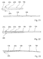
- FIG. 21 to 23 an alternative wiper lever with a wiper arm 10h and a wiper blade 12h is shown in various stages of manufacture, wherein the wiper arm 10h and the wiper blade 12h finished according to the invention are connected joint-free, by a resilient connection part 16h ( Fig. 23 ).
- the wiper arm 10h and the connecting part 16h are made in one piece and are formed by a common, elongated punched-bent part of a resilient steel sheet.
- the wiper arm 10h has at one end a recess 24h for coupling to a drive shaft, while at a second end of the wiper arm 10h, the connecting part 16g is arranged.
- the wiper blade 12h is formed by a stamped and bent part formed separately from the wiper arm 10h and connecting part 16h and has a smaller material thickness than the wiper arm 10h and the connecting part 16h.
- the wiper blade 12h is welded in a manufacturing stage with its longitudinal central portion with the connecting part 16h ( FIGS. 22 and 23 ). Further, in a bending process to the wiper arm 10h molded tabs 26h, 28h are bent by 90 ° in the direction of an underside of the wiper lever, which form a wiper blade guide on the inner circle of the wiper blade 12h.
- the wiper blade 12h is connected to the wiper arm 10h via its longitudinal middle section and via the connecting part 16h. In operation, in the region of a central circle of the wiper blade 12h or is transferred from the wiper arm 10h via the connecting part 16h and over the longitudinal center portion of the wiper blade 12h a bearing force on the wiper blade 12h.
- a wiper strip designed as a hollow profile can be pushed onto a wiper strip carrier element 18h of the wiper blade 12h running over the entire surface or without a recess, or a wiper strip can be glued on.
- the wiper strip carrier element 18h could also be designed with a slot-shaped opening extending over its length and closed at one end or at both ends, into which a wiper strip can be inserted.
Landscapes
- Engineering & Computer Science (AREA)
- Mechanical Engineering (AREA)
- Ink Jet (AREA)
- Pivots And Pivotal Connections (AREA)
- Body Structure For Vehicles (AREA)
Description
Die Erfindung geht aus von einem Wischhebel nach dem Oberbe- griff des Anspruchs 1.The invention is based on a wiper lever according to the preamble of claim 1.
Aus der
Weiterhin sind aus der
Die Erfindung geht aus von einem Wischhebel mit einem Wischarm und einem Wischblatt.The invention is based on a wiper lever with a wiper arm and a wiper blade.
Es wird vorgeschlagen, dass der Wischarm und das Wischblatt gelenkfrei miteinander verbunden sind. Es kann eine besonders einfache und flach bauende Konstruktion erreicht und insbesondere können die Bauteileanzahl, der Montageaufwand und die Kosten reduziert werden. Mithilfe eines Reversiermotors kann der Wischhebel in eine erweiterte Parklage in eine besonders schmale Ausnehmung geführt werden, beispielsweise unter eine Motorhaube oder in eine speziell geformte A-Säule eines Kraftfahrzeugs. Ferner können verschleiß- und fehleranfällige Bauteile, insbesondere Lagerbauteile, zumindest weitgehend reduziert werden.It is proposed that the wiper arm and the wiper blade are connected to each other without joints. It can achieve a particularly simple and flat design and construction, in particular, the number of components, assembly costs and costs can be reduced. By means of a reversible motor, the wiper lever can be guided into an extended parking position in a particularly narrow recess, for example under a hood or in a specially shaped A-pillar of a motor vehicle. Furthermore, wear-prone and error-prone components, in particular bearing components, can be at least largely reduced.
Unter gelenkfrei verbunden soll in diesem Zusammenhang verstanden werden, dass der Wischarm und das Wischblatt ohne eine materiell ausgeführte Schwenkachse verbunden sind, um die der Wischarm und das Wischblatt relativ zueinander schwenkbar wären. Bauteile, die infolge einer Materialverformung, insbesondere infolge einer elastischen Verformung, eine Relativbewegung zwischen dem Wischarm und dem Wischblatt ermöglichen, sollen in diesem Zusammenhang nicht als Gelenk angesehen werden und sollen insbesondere vom Schutzbereich mit umfasst sein, wie beispielsweise Filmscharniere, federelastische Teilstücke usw.Under joint-free connected should be understood in this context that the wiper arm and the wiper blade are connected without a materially executed pivot axis about which the wiper arm and the wiper blade would be pivotable relative to each other. Components which permit a relative movement between the wiper arm and the wiper blade as a result of deformation of the material, in particular as a result of elastic deformation, should not be regarded as hinges in this context and should in particular be included in the scope of protection, such as, for example, film hinges, spring-elastic sections, etc.
Ist der Wischarm und das Wischblatt über wenigstens ein federelastisches Verbindungsteil verbunden, kann vorteilhaft ein Ausgleich einer Hubbewegung bzw. einer Relativbewegung zwischen dem Wischarm und dem Wischblatt während des Betriebs sicher gestellt werden. Grundsätzlich ist jedoch auch denkbar, dass der Wischarm und das Wischblatt über ein im Wesentlichen starres Verbindungsteil miteinander verbunden sind. Ein Ausgleich von Relativbewegungen zwischen dem Wischarm und dem Wischblatt könnte dabei durch den Wischarm und/oder durch das Wischblatt selbst erreicht werden.If the wiper arm and the wiper blade are connected via at least one spring-elastic connecting part, compensation for a stroke movement or a relative movement between the wiper arm and the wiper blade during operation can advantageously be ensured. In principle, however, it is also conceivable that the wiper arm and the wiper blade are connected to one another via a substantially rigid connecting part. A compensation of relative movements between the wiper arm and the wiper blade could be achieved by the wiper arm and / or by the wiper blade itself.
In einer weiteren Ausgestaltung der Erfindung wird vorgeschlagen, dass das Wischblatt ein gelenkfrei mit dem Wischarm verbundenes, federelastisches Wischleistenträgerelement aufweist, an dessen konkaven Seite sich im montierten Zustand eine Wischlippe einer Wischleiste erstreckt. Derartige, so genannte gelenkfreie Wischblätter können besonders flachbauend ausgeführt und es kann ein insgesamt besonders flachbauender Wischhebel erreicht werden. Zudem kann die Bauteileanzahl gegenüber Bügelwischblättern, die grundsätzlich ebenfalls in einem erfindungsgemäßen Wischhebel integrierbar sind, erheblich reduziert werden.In a further embodiment of the invention, it is proposed that the wiper blade has a spring-elastic wiper strip carrier element connected to the wiper arm in a joint-free manner, on the concave side of which a wiper lip of a wiper strip extends in the mounted state. Such, so-called joint-free wiper blades can be made particularly flat and it can be achieved a total of particularly flat wiper lever. In addition, the number of components compared with ironing wiper blades, which are basically also integrated in a wiper lever according to the invention, can be significantly reduced.
Zudem wird vorgeschlagen, dass der Wischarm wenigstens ein federelastisches Trägerelement aufweist. Auf ein Gelenk im Wischarm kann verzichtet und es können zusätzliche Bauteile eingespart und die Gesamtbauhöhe des Wischhebels kann weiter reduziert werden. Ferner können in einer Kombination mit einem bügellosen Wischblatt der Wischarm und das Wischblatt vorteilhaft auf zumindest im Wesentlichen gleichen Produktionsmaschinen kostengünstig hergestellt werden.In addition, it is proposed that the wiper arm has at least one resilient carrier element. On a joint in the wiper arm can be omitted and it can save additional components and the overall height of the wiper lever can be further reduced. Furthermore, in combination with a non-iron wiper blade, the wiper arm and the wiper blade are advantageously produced inexpensively on at least substantially the same production machines.
Das Verbindungsteil kann vorteilhaft mit wenigstens einem federelastischen Trägerelement, wie einem Wischleistenträgerelement und/oder einem Trägerelement des Wischarms einstückig ausgeführt sein, wodurch zusätzliche Bauteile, Montageaufwand und Kosten eingespart werden können.The connecting part may advantageously be made in one piece with at least one resilient support element, such as a wiper support element and / or a support element of the wiper arm, whereby additional components, assembly costs and costs can be saved.
Da der Wischarm und das Wischblatt zumindest teilweise einstückig ausgeführt sind, können wiederum zusätzliche Bauteile eingespart und es kann eine besonders kostengünstige Herstellung erreicht werden, und zwar insbesondere, wenn der Wischarm und das Wischblatt aus einem gemeinsamen Stanz-Biegeteil gebildet sind. Ferner kann eine besonders harmonische Biegelinie des Wischhebels erzielt und Schwachstellen können einfach vermieden werden.Since the wiper arm and the wiper blade are at least partially made in one piece, in turn additional components can be saved and a particularly cost-effective production can be achieved, in particular if the wiper arm and the wiper blade are formed from a common stamped and bent part. Furthermore, a particularly harmonic bending line of the wiper lever can be achieved and weak points can be easily avoided.
In einer weiteren Ausgestaltung der Erfindung wird vorgeschlagen, dass das Wischblatt über sein äußeres Wischblattende mit dem Wischarm verbunden ist bzw. eine Auflagekrafteinleitungsstelle an seinem äußeren Wischblattende aufweist. Es kann ein langer Wischarm erzielt und insbesondere bei einer Ausgestaltung des Wischarms mit einem federelastischen Trägerelement eine vorteilhaft große Länge erreicht werden, über die eine Relativbewegung zwischen dem Wischarm und dem Wischblatt ausgeglichen und eine große Relativbewegung des Wischblatts im Wesentlichen senkrecht zur Windschutzscheibe ermöglicht werden kann, beispielsweise zur komfortablen Reinigung der Windschutzscheibe. Ferner kann ein besonders kleiner Innenkreis des Wischblatts bzw. ein kleiner Abstand eines inneren Wischblattendes zu einer Antriebswelle erreicht werden, über die der Wischhebel antreibbar ist.In a further embodiment of the invention, it is proposed that the wiper blade is connected to the wiper arm via its outer wiper blade end or has a contact force introduction point at its outer wiper blade end. It can be achieved a long wiper arm and in particular in an embodiment of the wiper arm with a resilient support member an advantageously long length can be achieved over which compensates a relative movement between the wiper arm and the wiper blade and a large relative movement of the wiper blade substantially perpendicular to the windshield can be made possible for example, for comfortable cleaning of the windshield. Furthermore, a particularly small inner circle of the wiper blade or a small distance of an inner wiper blade end can be achieved to a drive shaft, via which the wiper lever is driven.
Ist das Wischblatt über sein inneres Wischblattende mit dem Wischarm verbunden bzw. weist das Wischblatt eine Auflagekrafteinleitungsstelle an seinem inneren Wischblattende auf, kann ein vibrationsunempfindlicher Wischhebel erreicht und es kann eine Konstruktion mit geringem Materialeinsatz erzielt werden.If the wiper blade is connected to the wiper arm via its inner wiper blade end or if the wiper blade has a contact force introduction point at its inner wiper blade end, a vibration-insensitive wiper lever can be achieved and a design with a low use of material can be achieved.
Ist das Wischblatt über einen Bereich zwischen seinen Wischblattenden und insbesondere über seinen Längsmittelabschnitt mit dem Wischarm verbunden bzw. weist das Wischblatt eine Auflagekrafteinleitungsstelle in seinem Längsmittelabschnitt auf, kann eine besonders vorteilhafte, insbesondere zumindest weitgehend symmetrische Kräfteverteilung am Wischblatt erzielt werden.If the wiper blade is connected to the wiper arm over an area between its wiper blade ends and in particular via its longitudinal middle section or if the wiper blade has a contact force introduction point in its longitudinal middle section, a particularly advantageous, in particular at least substantially symmetrical, force distribution on the wiper blade can be achieved.
Anstatt alternativ können die vorgeschlagenen Verbindungsstellen bzw. Auflagekrafteinleitungsstellen, und zwar am äußeren Wischblattende, am inneren Wischblattende und in einem Bereich zwischen den Wischblattenden, auch beliebig kombiniert werden.Instead of the alternative, the proposed connection points or contact force introduction points, namely at the outer wiper blade end, at the inner wiper blade end and in a region between the wiper blade ends, can also be combined as desired.
Der Wischarm ist über wenigstens ein Querstück mit dem Wischblatt verbunden, wodurch einfach, mit geringem Materialeinsatz ein vorteilhafter Abstand zwischen dem Wischblatt und dem Wischarm erreicht werden kann, über den Relativbewegungen zwischen den beiden Bauteilen ausgleichbar sind, beispielsweise über eine elastische Verformung. Zudem kann durch das Querstück vorteilhaft ein sich während des Betriebs ergebendes Wischfeld eingestellt werden. Der Einsatz eines Querstücks eignet sich besonders für eine Verbindung des Wischblatts an seinem inneren Wischblattende oder in seinem Längsmittelabschnitt mit dem Wischarm, kann jedoch auch für eine Verbindung des Wischblatts an seinem äußeren Wischblattende mit dem Wischarm verwendet werden.The wiper arm is connected to the wiper blade via at least one crosspiece, whereby an advantageous distance between the wiper blade and the wiper arm can be achieved easily, with little use of material, via which relative movements between the two components can be compensated, for example via an elastic deformation. In addition, can be adjusted by the crosspiece advantageously a resulting during operation wiping field. The use of a crosspiece is particularly suitable for connection of the wiper blade to its inner wiper blade end or in its longitudinal central portion with the wiper arm, but can also be used for connection of the wiper blade at its outer wiper blade end with the wiper arm.
Ferner kann ein vorteilhafter Abstand zwischen dem Wischblatt und dem Wischarm erreicht werden, über den wiederum ein Bewegungsausgleich realisiert werden kann, indem der Wischarm und das Wischblatt über wenigstens eine Umlenkung mit einem Winkel größer als 90° verbunden sind.Furthermore, an advantageous distance between the wiper blade and the wiper arm can be achieved, via which, in turn, compensation for movement can be realized by connecting the wiper arm and the wiper blade via an at least one deflection at an angle greater than 90 °.
Weist das Wischblatt wenigstens eine schlitzförmige Ausnehmung zur Aufnahme einer Wischleiste auf, können bewährte Wischleisten einfach am Wischblatt montiert werden. Grundsätzlich ist jedoch auch der Einsatz geklebter Wischleisten oder von als Hohlprofil ausgebildeten Wischleisten denkbar.If the wiper blade has at least one slot-shaped recess for receiving a wiper strip, proven wiper strips can be easily mounted on the wiper blade. In principle, however, the use of glued wiper strips or designed as a hollow profile wiper strips is conceivable.
Der Wischarm und das Wischblatt werden vorteilhaft aus einem federelastischen Stahlblech gebildet, wodurch auf für bügellose Wischblätter bewährte Fertigungsanlagen zurückgegriffen werden kann. Es sind jedoch auch andere, dem Fachmann als sinnvoll erscheinende Materialien denkbar, wie beispielsweise faserverstärkte Kunststoffe usw.The wiper arm and the wiper blade are advantageously formed from a resilient steel sheet, which can be used on proven for ironless wiper blades production equipment. However, there are also other conceivable to those skilled in the useful materials, such as fiber-reinforced plastics, etc.
Um zumindest in einzelnen Bereichen eine erhöhte Steifigkeit zu erreichen, können zudem Sicken, U-Profile usw. vorgesehen werden, beispielsweise indem diese an den Wischarm oder an das Wischblatt angeformt oder indem zusätzliche Bauteile befestigt werden.In order to achieve increased rigidity, at least in individual areas, it is additionally possible to provide beads, U-profiles, etc., for example by integrating these onto the wiper arm or onto the wiper blade or by fastening additional components.
Ferner ist denkbar, am Wischblatt und/oder am Wischarm einen Windabweiser anzuordnen, der von einem zusätzlichen Bauteil gebildet sein kann, beispielsweise von einem Kunststoffbauteil, oder zumindest teilweise einstückig an das Wischblatt und/oder an den Wischarm angeformt sein kann, beispielsweise indem dieser einstückig an ein Stanz-Biegeblechteil angeformt ist.Furthermore, it is conceivable to arrange a wind deflector on the wiper blade and / or on the wiper arm, which can be formed by an additional component, for example by a plastic component, or at least partially integrally formed on the wiper blade and / or on the wiper arm, for example by integrally is formed on a stamped and bent sheet metal part.
Der erfindungsgemäße Wischhebel kann als vollwertiger Wischhebel sowohl für eine Front- als auch für eine Heckscheibe angewendet ausgeführt werden oder kann als so genannter Transportwischhebel ausgeführt werden, der vor einer Auslieferung an einen Endkunden durch einen anderen Wischhebel ersetzt wird.The wiper lever according to the invention can be performed as a full wiper lever applied both for a front and for a rear window or can be designed as a so-called transport wiper lever, which is replaced by a separate wiper before delivery to an end customer.
Weitere Vorteile ergeben sich aus der folgenden Zeichnungsbeschreibung. In der Zeichnung sind Ausführungsbeispiele der Erfindung dargestellt. Die Zeichnung, die Beschreibung und die Ansprüche enthalten zahlreiche Merkmale in Kombination. Der Fachmann wird die Merkmale zweckmäßigerweise auch einzeln betrachten und zu sinnvollen weiteren Kombinationen zusammenfassen.Further advantages emerge from the following description of the drawing. In the drawings, embodiments of the invention are shown. The drawing, the description and the claims contain numerous features in combination. The expert will conveniently consider the features individually and summarize meaningful further combinations.
Es zeigen:
- Fig. 1
- einen Wischllebel mit einer Auflagekrafteinleitungsstelle an einem äußeren Wischblattende in einer Ansicht von unten vor einem Biegeprozess,
- Fig. 2
- den Wischhebel aus
Fig. 1 nach einem ersten Biegevorgang, - Fig. 3
- den Wischhebel aus
Fig. 1 nach einem zweiten Biegevorgang in einer Seitenansicht, - Fig. 4
- einen alternativen Wischhebel zu
Fig. 1 mit einer Auflagekrafteinleitungsstelle an einem inneren Wischblattende in einer Ansicht von unten vor einem Biegeprozess, - Fig. 5
- den Wischhebel aus
Fig. 4 nach dem Biegeprozess in einer Seitenansicht, - Fig. 6
- einen alternativen Wischhebel zu
Fig. 4 mit einem von einem Querstück gebildeten Verbindungsteil in einer Ansicht von unten, - Fig. 7
- den Wischhebel aus
Fig. 6 in einer Seitenansicht, - Fig. 8
- eine Ansicht in Richtung VIII in
Fig. 7 , - Fig. 9
- einen alternativen Wischhebel zu
Fig. 6 vor einem Biegeprozess zur Anformung einer 180°-Umlenkung von unten, - Fig. 10
- den Wischhebel aus
Fig. 9 nach dem Biegeprozess, - Fig. 11
- den Wischhebel aus
Fig. 10 in einer Seitenansicht, - Fig. 12
- eine Ansicht in Richtung XII in
Fig. 11 , - Fig. 13
- einen zu
Fig. 1 alternativen Wischllebel mit einer Auflagekrafteinleitungsstelle an einem Längsrnittelabsclmitt eines Wischblatts in einer Ansicht von unten, - Fig. 14
- den Wischhebel aus
Fig. 13 in einer Seitenansicht - Fig. 15 5
- einen zu
Fig. 13 alternativen Wischhebel mit einem einzelnen Querstück in einer Ansicht von unten, - Fig. 16
- den Wischhebel aus
Fig. 15 in einer Seitenansicht,
- Fig. 17
- einen zu
Fig. 15 alternativen Wischhebel vor einem Biegeprozess zur Anformung einer 180°-Umlenkung, - Fig. 18
- den Wischhebel aus
Fig. 17 nach dem Biegeprozess, - Fig. 19
- den Wischhebel aus
Fig. 18 in einer Seitenansicht, - Fig. 20
- eine Ansicht in Richtung XX in
Fig. 19 , - Fig. 21
- einen alternativen Wischhebel zu
Fig. 13 vor einer Verbindung eines Wischarms und eines Wischblatts, - Fig. 22
- den Wischhebel aus
Fig. 21 nach der Verbindung des Wischarms und des Wischblatts und - Fig. 23
- den Wischhebel aus
Fig. 22 in einer Seitenansicht.
- Fig. 1
- a wiper blade with a contact force introduction point at an outer wiper blade end in a view from below before a bending process,
- Fig. 2
- off the wiper lever
Fig. 1 after a first bending process, - Fig. 3
- off the wiper lever
Fig. 1 after a second bending process in a side view, - Fig. 4
- an alternative wiper lever too
Fig. 1 with a contact force introduction point at an inner wiper blade end in a view from below before a bending process, - Fig. 5
- off the wiper lever
Fig. 4 after the bending process in a side view, - Fig. 6
- an alternative wiper lever too
Fig. 4 with a connecting piece formed by a crosspiece in a view from below, - Fig. 7
- off the wiper lever
Fig. 6 in a side view, - Fig. 8
- a view towards VIII in
Fig. 7 . - Fig. 9
- an alternative wiper lever too
Fig. 6 before a bending process for forming a 180 ° deflection from below, - Fig. 10
- off the wiper lever
Fig. 9 after the bending process, - Fig. 11
- off the wiper lever
Fig. 10 in a side view, - Fig. 12
- a view towards XII in
Fig. 11 . - Fig. 13
- one too
Fig. 1 alternative wiper blade with a contact force introduction point on a longitudinal member of a wiper blade in a view from below, - Fig. 14
- off the wiper lever
Fig. 13 in a side view - Fig. 15 5
- one too
Fig. 13 alternative wiper lever with a single cross piece in a view from below, - Fig. 16
- off the wiper lever
Fig. 15 in a side view,
- Fig. 17
- one too
Fig. 15 alternative wiper lever before a bending process for forming a 180 ° deflection, - Fig. 18
- off the wiper lever
Fig. 17 after the bending process, - Fig. 19
- off the wiper lever
Fig. 18 in a side view, - Fig. 20
- a view towards XX in
Fig. 19 . - Fig. 21
- an alternative wiper lever too
Fig. 13 before connecting a wiper arm and a wiper blade, - Fig. 22
- off the wiper lever
Fig. 21 after connecting the wiper arm and the wiper blade and - Fig. 23
- off the wiper lever
Fig. 22 in a side view.
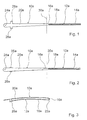
In den
Das Wischblatt 12a weist ein gelenkfrei mit dem Wischarm 10a verbundenes, federelastisches, bogenförmiges Wischleistenträgerelement 18a auf, an dessen konkaven Seite sich im montierten Zustand eine Wischlippe einer Wischleiste erstreckt (
Der Wischarm 10a weist ein federelastisches Trägerelement 20a auf, das an seinem freien Ende eine Ausnehmung 24a zur Kopplung an eine Antriebswelle aufweist. Vor einem sich an einen Stanzprozess anschließenden Biegeprozess ist der Wischhebel im Wesentlichen eben ausgeführt und weist ausgehend von der Ausnehmung 24a kurz nach derselben in Richtung zum Wischblatt 12a zwei sich quer zur Längsrichtung erstreckende, an den Wischarm 10a einstückig angeformte Laschen 26a, 28a auf (
Im Biegeprozess werden die Laschen 26a, 28a um 90° in Richtung zu einer Unterseite des Wischhebels umgebogen (
Es entsteht im Bereich des Verbindungsteils 16a im Wesentlichen eine 180°-Umlenkung 22a, über die der Wischarm 10a und das Wischblatt 12a miteinander verbunden sind (
Das Wischblatt 12a ist über sein äußeres Wischblattende und über das Verbindungsteil 16a mit dem Wischarm 10a verbunden. Im Betrieb wird im Bereich eines Außenkreises des Wischblatts 12a bzw. wird vom Wischarm 10a über das Verbindungsteil 16a und über das äußere Wischblattende eine Auflagekraft auf das Wischblatt 12a übertragen.The
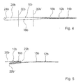
In den
Der Wischhebel umfasst einen Wischarm 10b und ein Wischblatt 12b, die über ein federelastisches Verbindungsteil 16b gelenkfrei verbunden sind. Der Wischarm 10b, das Verbindungsteil 16b und das Wischblatt 12b sind einstückig ausgeführt und sind von einem gemeinsamen, langgestreckten Stanz-Biegeteil aus einem federelastischen Stahlblech gebildet.The wiper lever comprises a
Vor einem sich an einen Stanzprozess anschließenden Biegeprozess ist der Wischhebel im Wesentlichen eben ausgeführt (
Das Wischblatt 12b ist über sein inneres Wischblattende und über das Verbindungsteil 16b mit dem Wischarm 10b verbunden. Im Betrieb wird im Bereich eines Innenkreises des Wischblatts 12b bzw. wird vom Wischarm 10b über das Verbindungsteil 16b und über das innere Wischblattende eine Auflagekraft auf das Wischblatt 12b übertragen.
Zur Befestigung einer Wischleiste am Wischblatt 12b ist in einem federelastischen, bogenförmigen Wischleistenträgerelement 18b des Wischblatts 12b eine schlitzförmige Ausnehmung 14b eingebracht, die im Bereich des freien Endes des Wischblatts 12b geschlossen ausgeführt ist.The
For fastening a wiper strip on the
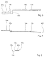
In den
Das Wischblatt 12c ist über sein inneres Wischblattende und über das Verbindungsteil 16c mit dem Wischarm 10c verbunden. Um senkrecht zu einer zu wischenden Windschutzscheibe einen Höhenversatz zwischen dem Wischarm 10c und dem Wischblatt 12c zu erreichen, ist das Verbindungsteil 16c abgewinkelt ausgeführt (
Auf ein ganzflächig bzw. ohne Ausnehmung ausgeführtes Wischleistenträgerelement 18c des Wischblatts 12c kann eine als Hohlprofil ausgefülu-te Wischleiste aufgeschoben oder es kann eine Wischleiste aufgeklebt werden.A wiper strip filled out as a hollow profile can be pushed onto a wiper
In
Vor einem sich an einen Stanzprozess anschließenden Biegeprozess ist der Wischhebel im Wesentlichen eben ausgeführt (
Es entsteht im Bereich des Verbindungsteils 16d im Wesentlichen eine 180°-Umlenkung 22d, über die der Wischarm 10d und das Wischblatt 12a miteinander verbunden sind (
Zusätzlich oder alternativ zum Wischblatt 12d könnte auch der Wischarm 10d um die Biegeachse 30d gebogen werden.In addition or as an alternative to the
Das Wischblatt 12d ist über sein inneres Wischblattende und über das Verbindungsteil 16d mit dem Wischarm 10d verbunden.
Im Betrieb wird im Bereich eines Innenkreises des Wischblatts 12d bzw. wird vom Wischarm 10d über das Verbindungsteil 16d und über das innere Wischblattende eine Auflagekraft auf das Wischblatt 12d übertragen.The
In operation, in the region of an inner circle of the
Zur Befestigung einer Wischleiste am Wischblatt 12d ist in einem federelastischen, bogenförmigen Wischleistenträgerelement 18d des Wischblatts 12d eine schlitzförmige Ausnehmung 14d eingebracht, die im Bereich des freien Endes des Wischblatts 12d offen ausgeführt ist.In order to fasten a wiper strip to the
In den
Das Wischblatt 12e ist über seinen Längsmittelabschnitt und über die Verbindungsteile 16e, 16e' mit dem Wischarm 10e verbunden. Im Betrieb wird im Bereich eines Mittelkreises des Wischblatts 12e bzw. wird vom Wischarm 10e über die Verbindungsteile 16e, 16e' und über den Längsmittelabschnitt des Wischblatts 12e eine Auflagekraft auf das Wischblatt 12d übertragen.The
Auf ein ganzflächig bzw. ohne Ausnehmung ausgeführtes Wischleistenträgerelement 18e des Wischblatts 12e kann eine als Hohlprofil ausgeführte Wischleiste aufgeschoben oder es kann eine Wischleiste aufgeklebt werden. Das Wischleistenträgerelement 18e könnte jedoch auch mit einer sich über dessen Länge erstreckenden, schlitzförmigen, zu einem Ende oder zu beiden Enden hin offenen Ausnehmung ausgeführt sein, in die eine Wischleiste eingeschoben werden kann.A wiper strip designed as a hollow profile can be pushed onto a wiper
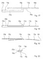
In
In den
Vor einem sich an einen Stanzprozess anschließenden Biegeprozess ist der Wischhebel im Wesentlichen eben ausgeführt (
Es entsteht im Bereich des Verbindungsteils 16g im Wesentlichen eine 180°-Umlenkung 22g, über die der Wischarm 10g und das Wischblatt 12g miteinander verbunden sind (
In the region of the connecting
Das Wischblatt 12g ist über seinen Längsmittelabschnitt und über das Verbindungsteil 16g mit dem Wischarm 10g verbunden. Im Betrieb wird im Bereich eines Mittelkreises des Wischblatts 12g bzw. wird vom Wischarm 10g über das Verbindungsteil 16g und über den Längsmittelabschnitt des Wischblatts 12g eine Auflagekraft auf das Wischblatt 12g übertragen.The
Auf ein ganzflächig bzw. ohne Ausnehmung ausgeführtes Wischleistenträgerelement 18g des Wischblatts 12g kann eine als Hohlprofil ausgeführte Wischleiste aufgeschoben oder es kann eine Wischleiste aufgeklebt werden. Das Wischleistenträgerelement 18g könnte jedoch auch mit einer sich über dessen Länge erstreckenden, schlitzförmigen, zu einem Ende oder zu beiden Enden hin geschlossenen Ausnehmung ausgeführt sein, in die eine Wischleiste eingeschoben werden kann.A wiper strip designed as a hollow profile can be pushed onto a wiper
In den
Das Wischblatt 12h wird in einer Fertigungsstufe mit seinem Längsmittelabschnitt mit dem Verbindungsteil 16h verschweißt (
Das Wischblatt 12h ist über seinen Längsmittelabschnitt und über das Verbindungsteil 16h mit dem Wischarm 10h verbunden. Im Betrieb wird im Bereich eines Mittelkreises des Wischblatts 12h bzw. wird vom Wischarm 10h über das Verbindungsteil 16h und über den Längsmittelabschnitt des Wischblatts 12h eine Auflagekraft auf das Wischblatt 12h übertragen.The
Auf ein ganzflächig bzw. ohne Ausnehmung ausgeführtes Wischleistenträgerelement 18h des Wischblatts 12h kann eine als Hohlprofil ausgeführte Wischleiste aufgeschoben oder es kann eine Wischleiste aufgeklebt werden.A wiper strip designed as a hollow profile can be pushed onto a wiper
Das Wischleistenträgerelement 18h könnte jedoch auch mit einer sich über dessen Länge erstreckenden, schlitzförmigen, zu einem Ende oder zu beiden Enden hin geschlossenen Ausnehmung ausgeführt sein, in die eine Wischleiste eingeschoben werden kann.However, the wiper
- 1010
- Wischarmwiper arm
- 1212
- Wischblattwiper blade
- 1414
- Ausnehmungrecess
- 1616
- Verbindungsteilconnecting part
- 1818
- WischleistenträgerelementWiper strip support element
- 2020
- Trägerelementsupport element
- 2222
- Umlenkungredirection
- 2424
- Ausnehmungrecess
- 2626
- Lascheflap
- 2828
- Lascheflap
- 3030
- Biegeachsebending axis
Claims (10)
- Wiper lever comprising a wiper arm (10a-10h) and a wiper blade (12a-12h) which is connected joint-free to the wiper arm (10a-10h), wherein the wiper arm (10a-10g) and the wiper blade (12a-12g) are designed at least partly in one piece, characterized in that the wiper blade (12e-12h) is connected, between its wiper blade ends, to the wiper arm (10e-10h) via at least one spring-elastic crosspiece.
- Wiper lever according to Claim 1, characterized in that the wiper arm (10a-10h) and the wiper blade (12a-12h) are connected via at least one spring-elastic connecting part (16a-16h).
- Wiper lever according to Claim 1 or 2, characterized in that the wiper blade (12a-12h) has a spring-elastic wiper strip carrier element (18a-18h) which is connected joint-free to the wiper arm (10a-10h) and on whose concave side a wiper lip of a wiper strip extends in the mounted state.
- Wiper lever according to one of the preceding claims, characterized in that the wiper arm (10a-10h) has at least one spring-elastic carrier element (20a-20h).
- Wiper lever at least according to Claim 2, characterized in that the connecting part (16a-16h) is designed in one piece with at least one spring-elastic carrier element (18a-18g, 20a-20h).
- Wiper lever according to Claim 5, characterized in that the wiper arm (10a-10g) and the wiper blade (12a-12g) are formed from a common stamped and bent part.
- Wiper lever according to one of the preceding claims, characterized in that the wiper blade (12a) is also connected via its outer wiper blade end to the wiper arm (10a).
- Wiper lever according to one of the preceding claims, characterized in that the wiper blade (12b-12d) is also connected via its inner wiper blade end to the wiper arm (10b-10d).
- Wiper lever according to one of the preceding claims, characterized in that the wiper arm (10a, 10b, 10d, 10g) and the wiper blade (12a, 12b, 12d, 12g) are connected via at least one deflection (22a, 22b, 22d, 22g) with an angle of greater than 90°.
- Wiper lever according to one of the preceding claims, characterized in that the wiper blade (12a, 12b, 12d) has at least one slot-like cutout (14a, 14b, 14d) for receiving a wiper strip.
Applications Claiming Priority (3)
| Application Number | Priority Date | Filing Date | Title |
|---|---|---|---|
| DE10259479A DE10259479A1 (en) | 2002-12-19 | 2002-12-19 | wiper lever |
| DE10259479 | 2002-12-19 | ||
| PCT/DE2003/002602 WO2004056626A1 (en) | 2002-12-19 | 2003-08-04 | Wiper crank with a wiper arm and a wiper blade |
Publications (2)
| Publication Number | Publication Date |
|---|---|
| EP1575813A1 EP1575813A1 (en) | 2005-09-21 |
| EP1575813B1 true EP1575813B1 (en) | 2008-02-27 |
Family
ID=32403951
Family Applications (1)
| Application Number | Title | Priority Date | Filing Date |
|---|---|---|---|
| EP03813523A Expired - Lifetime EP1575813B1 (en) | 2002-12-19 | 2003-08-04 | Wiper crank with a wiper arm and a wiper blade |
Country Status (6)
| Country | Link |
|---|---|
| US (1) | US20080052864A1 (en) |
| EP (1) | EP1575813B1 (en) |
| CN (1) | CN100408394C (en) |
| DE (2) | DE10259479A1 (en) |
| ES (1) | ES2299763T3 (en) |
| WO (1) | WO2004056626A1 (en) |
Cited By (1)
| Publication number | Priority date | Publication date | Assignee | Title |
|---|---|---|---|---|
| DE102012112526A1 (en) | 2012-12-18 | 2014-06-18 | Dr. Ing. H.C. F. Porsche Aktiengesellschaft | Wiper lever of a motor vehicle windshield wiper |
Families Citing this family (10)
| Publication number | Priority date | Publication date | Assignee | Title |
|---|---|---|---|---|
| DE102005048344A1 (en) * | 2005-10-10 | 2007-04-12 | Robert Bosch Gmbh | wiper arm |
| ITTO20070136A1 (en) | 2007-02-27 | 2008-08-28 | Giovanni Creaco | WIPER FOR MOTOR VEHICLES. |
| DE102012210945A1 (en) * | 2012-06-27 | 2014-01-02 | Robert Bosch Gmbh | wiper device |
| FR2995850B1 (en) * | 2012-09-27 | 2015-06-05 | Valeo Systemes Dessuyage | WINDOW CLEANING SYSTEM OF A GLASS, IN PARTICULAR REAR WINDOW OF A MOTOR VEHICLE |
| DE102014209269A1 (en) * | 2014-05-15 | 2015-11-19 | Volkswagen Aktiengesellschaft | windshield wipers |
| DE102014215831B4 (en) * | 2014-08-11 | 2025-01-23 | Robert Bosch Gmbh | windshield wiper system |
| FR3031948A1 (en) * | 2015-01-22 | 2016-07-29 | Peugeot Citroen Automobiles Sa | WIPING DEVICE FOR WINDSHIELD OF MOTOR VEHICLE |
| FR3035049A1 (en) * | 2015-04-17 | 2016-10-21 | Valeo Systemes Dessuyage | WIPER BLADE AND WIPE ASSEMBLY COMPRISING SUCH A BROOM |
| FR3055280B1 (en) * | 2016-08-24 | 2018-08-31 | Valeo Systemes D'essuyage | ASSEMBLY ASSEMBLY OF A WIPER BLADE ON A DRIVE SHAFT |
| FR3106548B1 (en) * | 2020-01-28 | 2022-10-28 | Valeo Systemes Dessuyage | Small area wiping |
Family Cites Families (7)
| Publication number | Priority date | Publication date | Assignee | Title |
|---|---|---|---|---|
| FR1217680A (en) * | 1958-10-01 | 1960-05-05 | Wiper blade for flat or curved windshields of vehicles | |
| DE2364622A1 (en) * | 1972-12-28 | 1974-07-04 | British Aluminium Co Ltd | WINDSHIELD WIPERS |
| FR2551709B1 (en) * | 1983-09-13 | 1987-06-12 | Champion Spark Plug Europ | WINDSCREEN WIPER SYSTEM FOR MOTOR VEHICLES |
| DE19856300A1 (en) | 1998-12-07 | 2000-06-08 | Bosch Gmbh Robert | Wiper blade for windows of motor vehicles |
| WO2002012033A1 (en) * | 2000-08-07 | 2002-02-14 | Valeo Auto-Electric Wischer Und Motoren Gmbh | Wiper device, in particular for motor vehicles |
| DE10108200A1 (en) * | 2001-02-21 | 2002-08-22 | Bosch Gmbh Robert | Wiper device, in particular for windows of motor vehicles |
| DE10109088B4 (en) * | 2001-02-24 | 2016-10-06 | Valeo Auto-Electric Wischer Und Motoren Gmbh | Wiper arm-wiper blade assembly |
-
2002
- 2002-12-19 DE DE10259479A patent/DE10259479A1/en not_active Withdrawn
-
2003
- 2003-08-04 ES ES03813523T patent/ES2299763T3/en not_active Expired - Lifetime
- 2003-08-04 CN CNB038113813A patent/CN100408394C/en not_active Expired - Fee Related
- 2003-08-04 EP EP03813523A patent/EP1575813B1/en not_active Expired - Lifetime
- 2003-08-04 WO PCT/DE2003/002602 patent/WO2004056626A1/en not_active Ceased
- 2003-08-04 US US10/539,990 patent/US20080052864A1/en not_active Abandoned
- 2003-08-04 DE DE50309278T patent/DE50309278D1/en not_active Expired - Lifetime
Cited By (2)
| Publication number | Priority date | Publication date | Assignee | Title |
|---|---|---|---|---|
| DE102012112526A1 (en) | 2012-12-18 | 2014-06-18 | Dr. Ing. H.C. F. Porsche Aktiengesellschaft | Wiper lever of a motor vehicle windshield wiper |
| WO2014095006A2 (en) | 2012-12-18 | 2014-06-26 | Dr. Ing. H.C. F. Porsche Aktiengesellschaft | Wiper lever of a motor vehicle windshield wiper |
Also Published As
| Publication number | Publication date |
|---|---|
| EP1575813A1 (en) | 2005-09-21 |
| DE10259479A1 (en) | 2004-07-01 |
| US20080052864A1 (en) | 2008-03-06 |
| ES2299763T3 (en) | 2008-06-01 |
| CN100408394C (en) | 2008-08-06 |
| WO2004056626A1 (en) | 2004-07-08 |
| CN1652957A (en) | 2005-08-10 |
| DE50309278D1 (en) | 2008-04-10 |
Similar Documents
| Publication | Publication Date | Title |
|---|---|---|
| EP1461235B1 (en) | Windscreen wiper comprising a wiper arm | |
| EP1547884B1 (en) | Wiper blade for cleaning glass panes, in particular of vehicles | |
| EP1363816B1 (en) | Wiper arm with a pivoting connected wiper blade | |
| EP1458600B1 (en) | Windscreen wiper with a wiper arm | |
| EP1332075B1 (en) | Device for detachably and hingedly connecting a wiper blade for cleaning panes to a wiper arm | |
| EP1053143B1 (en) | Device for an articulated connection between a wiper blade for panels of glass in motor vehicles and a wiper arm | |
| EP1117576B1 (en) | Wiper device for motor vehicle windows comprising a wiper arm which can move between return positions and which is loaded toward the window | |
| EP1494903B1 (en) | Wiper lever comprising a wiper arm and a wiper blade which is connected to the same in an articulated manner, for cleaning windows, especially windows pertaining to motor vehicles | |
| EP1501710B1 (en) | Wiper blade | |
| EP2271524B1 (en) | Device for the articulated connection of a wiper blade to a wiper arm | |
| WO1999012784A1 (en) | Wiper blade for cleaning automobile windscreens | |
| DE19833666A1 (en) | Wiper blade for windows of motor vehicles | |
| EP1056628A1 (en) | Device for the articulated connecting of a wiper blade for motor vehicle windows to a wiper arm and method for producing said connection | |
| DE19833665A1 (en) | Device for connecting a wiper blade for windows of motor vehicles to a driven wiper arm guided at one end on the motor vehicle | |
| EP1322507A1 (en) | Windscreen wiper | |
| DE102005062462A1 (en) | Windscreen wiper is fitted with spoiler on opposite side of mounting from wiper blade which has longitudinal cavity and is made from softer plastic than mounting | |
| DE102011054123A1 (en) | Wiper blade for cleaning vehicle windows | |
| EP1575813B1 (en) | Wiper crank with a wiper arm and a wiper blade | |
| EP0923468A1 (en) | Device for linking a wiper blade to a wiper arm | |
| EP1296862A1 (en) | Wiper arm for automobiles | |
| EP1761421B1 (en) | Articulation between a wiper arm and a wiper arm mounting, and a windscreen wiper having such an articulation | |
| DE102011082676A1 (en) | Windscreen wiper for motor car, has support forming arc i.e. double-w-shaped arc, that connects lower leg running in extension of support with upper leg that runs parallel to support, where free ends of upper leg is fastened to end of arm | |
| DE10162397B4 (en) | wiper blade | |
| DE102011054066A1 (en) | Wiper blade for cleaning vehicle window pane, has connecting terminals that are connected with vehicle-side wash liquid supply conduit and wash liquid channel which is provided with spray orifices | |
| EP1666320B1 (en) | Wiper blade |
Legal Events
| Date | Code | Title | Description |
|---|---|---|---|
| PUAI | Public reference made under article 153(3) epc to a published international application that has entered the european phase |
Free format text: ORIGINAL CODE: 0009012 |
|
| 17P | Request for examination filed |
Effective date: 20050719 |
|
| AK | Designated contracting states |
Kind code of ref document: A1 Designated state(s): AT BE BG CH CY CZ DE DK EE ES FI FR GB GR HU IE IT LI LU MC NL PT RO SE SI SK TR |
|
| RBV | Designated contracting states (corrected) |
Designated state(s): DE ES FR GB IT |
|
| 17Q | First examination report despatched |
Effective date: 20060123 |
|
| GRAP | Despatch of communication of intention to grant a patent |
Free format text: ORIGINAL CODE: EPIDOSNIGR1 |
|
| GRAS | Grant fee paid |
Free format text: ORIGINAL CODE: EPIDOSNIGR3 |
|
| GRAA | (expected) grant |
Free format text: ORIGINAL CODE: 0009210 |
|
| AK | Designated contracting states |
Kind code of ref document: B1 Designated state(s): DE ES FR GB IT |
|
| REG | Reference to a national code |
Ref country code: GB Ref legal event code: FG4D Free format text: NOT ENGLISH |
|
| REF | Corresponds to: |
Ref document number: 50309278 Country of ref document: DE Date of ref document: 20080410 Kind code of ref document: P |
|
| REG | Reference to a national code |
Ref country code: ES Ref legal event code: FG2A Ref document number: 2299763 Country of ref document: ES Kind code of ref document: T3 |
|
| ET | Fr: translation filed | ||
| PLBE | No opposition filed within time limit |
Free format text: ORIGINAL CODE: 0009261 |
|
| STAA | Information on the status of an ep patent application or granted ep patent |
Free format text: STATUS: NO OPPOSITION FILED WITHIN TIME LIMIT |
|
| 26N | No opposition filed |
Effective date: 20081128 |
|
| REG | Reference to a national code |
Ref country code: FR Ref legal event code: PLFP Year of fee payment: 14 |
|
| REG | Reference to a national code |
Ref country code: FR Ref legal event code: PLFP Year of fee payment: 15 |
|
| REG | Reference to a national code |
Ref country code: FR Ref legal event code: PLFP Year of fee payment: 16 |
|
| PGFP | Annual fee paid to national office [announced via postgrant information from national office to epo] |
Ref country code: FR Payment date: 20190822 Year of fee payment: 17 Ref country code: ES Payment date: 20190919 Year of fee payment: 17 Ref country code: IT Payment date: 20190821 Year of fee payment: 17 |
|
| PGFP | Annual fee paid to national office [announced via postgrant information from national office to epo] |
Ref country code: GB Payment date: 20190827 Year of fee payment: 17 |
|
| PGFP | Annual fee paid to national office [announced via postgrant information from national office to epo] |
Ref country code: DE Payment date: 20191021 Year of fee payment: 17 |
|
| REG | Reference to a national code |
Ref country code: DE Ref legal event code: R119 Ref document number: 50309278 Country of ref document: DE |
|
| GBPC | Gb: european patent ceased through non-payment of renewal fee |
Effective date: 20200804 |
|
| PG25 | Lapsed in a contracting state [announced via postgrant information from national office to epo] |
Ref country code: DE Free format text: LAPSE BECAUSE OF NON-PAYMENT OF DUE FEES Effective date: 20210302 Ref country code: FR Free format text: LAPSE BECAUSE OF NON-PAYMENT OF DUE FEES Effective date: 20200831 |
|
| PG25 | Lapsed in a contracting state [announced via postgrant information from national office to epo] |
Ref country code: GB Free format text: LAPSE BECAUSE OF NON-PAYMENT OF DUE FEES Effective date: 20200804 |
|
| REG | Reference to a national code |
Ref country code: ES Ref legal event code: FD2A Effective date: 20211227 |
|
| PG25 | Lapsed in a contracting state [announced via postgrant information from national office to epo] |
Ref country code: ES Free format text: LAPSE BECAUSE OF NON-PAYMENT OF DUE FEES Effective date: 20200805 |
|
| PG25 | Lapsed in a contracting state [announced via postgrant information from national office to epo] |
Ref country code: IT Free format text: LAPSE BECAUSE OF NON-PAYMENT OF DUE FEES Effective date: 20200804 |