EP1517636B1 - Kontrastmittelunterstützte bildgebung mit synchronisierter persistenz - Google Patents
Kontrastmittelunterstützte bildgebung mit synchronisierter persistenz Download PDFInfo
- Publication number
- EP1517636B1 EP1517636B1 EP03732849.9A EP03732849A EP1517636B1 EP 1517636 B1 EP1517636 B1 EP 1517636B1 EP 03732849 A EP03732849 A EP 03732849A EP 1517636 B1 EP1517636 B1 EP 1517636B1
- Authority
- EP
- European Patent Office
- Prior art keywords
- persistence
- contrast agent
- ultrasound
- tissue
- ultrasonic
- Prior art date
- Legal status (The legal status is an assumption and is not a legal conclusion. Google has not performed a legal analysis and makes no representation as to the accuracy of the status listed.)
- Expired - Lifetime
Links
Images


Classifications
-
- A—HUMAN NECESSITIES
- A61—MEDICAL OR VETERINARY SCIENCE; HYGIENE
- A61B—DIAGNOSIS; SURGERY; IDENTIFICATION
- A61B8/00—Diagnosis using ultrasonic, sonic or infrasonic waves
- A61B8/48—Diagnostic techniques
- A61B8/481—Diagnostic techniques involving the use of contrast agents, e.g. microbubbles introduced into the bloodstream
-
- A—HUMAN NECESSITIES
- A61—MEDICAL OR VETERINARY SCIENCE; HYGIENE
- A61B—DIAGNOSIS; SURGERY; IDENTIFICATION
- A61B8/00—Diagnosis using ultrasonic, sonic or infrasonic waves
- A61B8/06—Measuring blood flow
-
- A—HUMAN NECESSITIES
- A61—MEDICAL OR VETERINARY SCIENCE; HYGIENE
- A61B—DIAGNOSIS; SURGERY; IDENTIFICATION
- A61B8/00—Diagnosis using ultrasonic, sonic or infrasonic waves
- A61B8/54—Control of the diagnostic device
- A61B8/543—Control of the diagnostic device involving acquisition triggered by a physiological signal
-
- G—PHYSICS
- G01—MEASURING; TESTING
- G01S—RADIO DIRECTION-FINDING; RADIO NAVIGATION; DETERMINING DISTANCE OR VELOCITY BY USE OF RADIO WAVES; LOCATING OR PRESENCE-DETECTING BY USE OF THE REFLECTION OR RERADIATION OF RADIO WAVES; ANALOGOUS ARRANGEMENTS USING OTHER WAVES
- G01S15/00—Systems using the reflection or reradiation of acoustic waves, e.g. sonar systems
- G01S15/88—Sonar systems specially adapted for specific applications
- G01S15/89—Sonar systems specially adapted for specific applications for mapping or imaging
- G01S15/8906—Short-range imaging systems; Acoustic microscope systems using pulse-echo techniques
- G01S15/8977—Short-range imaging systems; Acoustic microscope systems using pulse-echo techniques using special techniques for image reconstruction, e.g. FFT, geometrical transformations, spatial deconvolution, time deconvolution
-
- G—PHYSICS
- G01—MEASURING; TESTING
- G01S—RADIO DIRECTION-FINDING; RADIO NAVIGATION; DETERMINING DISTANCE OR VELOCITY BY USE OF RADIO WAVES; LOCATING OR PRESENCE-DETECTING BY USE OF THE REFLECTION OR RERADIATION OF RADIO WAVES; ANALOGOUS ARRANGEMENTS USING OTHER WAVES
- G01S7/00—Details of systems according to groups G01S13/00, G01S15/00, G01S17/00
- G01S7/52—Details of systems according to groups G01S13/00, G01S15/00, G01S17/00 of systems according to group G01S15/00
- G01S7/52017—Details of systems according to groups G01S13/00, G01S15/00, G01S17/00 of systems according to group G01S15/00 particularly adapted to short-range imaging
- G01S7/52023—Details of receivers
- G01S7/52036—Details of receivers using analysis of echo signal for target characterisation
- G01S7/52038—Details of receivers using analysis of echo signal for target characterisation involving non-linear properties of the propagation medium or of the reflective target
- G01S7/52039—Details of receivers using analysis of echo signal for target characterisation involving non-linear properties of the propagation medium or of the reflective target exploiting the non-linear response of a contrast enhancer, e.g. a contrast agent
-
- A—HUMAN NECESSITIES
- A61—MEDICAL OR VETERINARY SCIENCE; HYGIENE
- A61B—DIAGNOSIS; SURGERY; IDENTIFICATION
- A61B5/00—Measuring for diagnostic purposes; Identification of persons
- A61B5/24—Detecting, measuring or recording bioelectric or biomagnetic signals of the body or parts thereof
- A61B5/316—Modalities, i.e. specific diagnostic methods
- A61B5/318—Heart-related electrical modalities, e.g. electrocardiography [ECG]
- A61B5/346—Analysis of electrocardiograms
- A61B5/349—Detecting specific parameters of the electrocardiograph cycle
- A61B5/352—Detecting R peaks, e.g. for synchronising diagnostic apparatus; Estimating R-R interval
Definitions
- the present disclosure relates to ultrasonic imaging. More particularly, the invention relates to a system and method that improves contrast agent imaging diagnostic evaluations.
- Ultrasonic imaging has quickly replaced conventional X-rays in many clinical applications because of its image quality, safety, and low cost.
- Ultrasonic images are typically formed through the use of phased or linear array transducers which are capable of transmitting and receiving pressure waves directed into a medium such as the human body.
- Such transducers normally comprise multi-element piezoelectric materials, which vibrate in response to an applied voltage to produce the desired pressure waves.
- Piezoelectric transducer elements are typically constructed of lead zirconate titanate (PZT), with a plurality of elements being arranged to form a transducer assembly.
- PZT lead zirconate titanate
- a new generation ultrasonic transducer known as a micro-machined ultrasonic transducer (MUT) is also available.
- MUTs are typically fabricated using semiconductor-manufacturing techniques with a number of elements typically formed on a common substrate to form a transducer assembly. Regardless of the type of transducer element, the transducer elements may be further assembled into a housing possibly containing control electronics, the combination of which forms an ultrasonic probe.
- the ultrasonic probe may include acoustic matching layers between the surface of the various types of elements and the probe body. Ultrasonic probes may then be used along with an ultrasonic transceiver to transmit and receive ultrasonic pressure waves through the various tissues of the body.
- the various ultrasonic responses may be further processed by an ultrasonic imaging system to display the various structures and tissues of the body.
- the ultrasonic probe To obtain high quality images, the ultrasonic probe must be constructed so as to produce specified frequencies of pressure waves.
- low frequency pressure waves provide deep penetration into the medium (e.g ., the body), but produce poor resolution images due to the length of the transmitted wavelengths.
- high frequency pressure waves provide high resolution, but with poor penetration.
- the selection of a transmitting frequency has involved balancing resolution and penetration concerns.
- resolution has suffered at the expense of deeper penetration and vice versa .
- the frequency selection problem has been addressed by selecting the highest imaging frequency (i . e., best resolution) which offers adequate penetration for a given application. For example, in adult cardiac imaging, frequencies in the 2 MHz to 3 MHz range are typically selected in order to penetrate the chest wall. Lower frequencies have not been used due to the lack of sufficient image resolution. Higher frequencies are often used for radiology and vascular applications where fine resolution is required to image small lesions and arteries affected by stenotic obstructions.
- harmonic imaging is grounded on the phenomenon that objects, such as human tissues, develop and return their own non-fundamental frequencies, i.e., harmonics of the fundamental frequency. This phenomenon and increased image processing capabilities of digital technology, make it is possible to excite an object to be imaged by transmitting at a low (and therefore deeply penetrating) fundamental frequency ( f o ) and receiving reflections at a higher frequency harmonic ( e.g., 2 f o ) to form a high resolution image of an object.
- f o fundamental frequency
- harmonic e.g. 2 f o
- a wave having a frequency less than 2 MHz can be transmitted into the human body and one or more harmonic waves having frequencies greater than 3 MHz can be received to form the image.
- one or more harmonic waves having frequencies greater than 3 MHz can be received to form the image.
- broadband transducers are required which can transmit sufficient bandwidth about the fundamental frequency and receive sufficient bandwidth about the harmonic(s).
- the s4 transducer available with the SONOS TM 5500 an ultrasound imaging system manufactured by and commercially available from Agilent Technologies, U.S.A., has a suitable bandwidth to achieve harmonic imaging with a single transducer thus providing a significant clinical improvement.
- the combination of the s4 transducer and the SONOS TM 5500 provide multiple imaging parameter choices using a single transducer, thus providing a penetration choice as well as a resolution choice.
- Conventional ultrasound scanners can create two-dimensional B-mode images of tissue in which the brightness of a pixel is based on the intensity of the received ultrasonic echoes.
- color flow imaging the flow of blood or movement of tissue can be imaged. Measurement of blood flow in the heart and vessels using the Doppler effect is well known.
- the frequency shift of backscattered ultrasound waves may be used to measure the velocity of the backscatterers from tissues or blood.
- the frequency of sound waves reflecting from the inside of blood vessels, heart cavities, etc. is shifted in proportion to the velocity of the blood cells.
- the frequency of ultrasonic waves reflected from cells moving towards the transducer is positively shifted.
- the frequency of ultrasonic reflections from cells moving away from the transducer is negatively shifted.
- the Doppler shift may be displayed using different colors to represent speed and direction of flow. In order to assist diagnosticians and operators the color flow image may be superimposed on the B-mode image.
- Ultrasound images like other images are subject to noise which may adversely affect the intensity values associated with the various pixels used to recreate the object or objects being observed. Ultrasound images, like some other images, also suffer from the effects of temporal noise in real-time image sequences.
- Conventional ultrasound imaging systems normally have an image frame filtering function, which acts on data in either polar or Cartesian coordinate formats.
- One method for reducing temporal noise from an image is to use a filter which weights and sums corresponding pixel intensity values from the previous frame with a present input frame to generate a display pixel intensity.
- This is sometimes called “temporal filtering” or “persistence filtering.”
- a previous display frame's pixel may be averaged with an input frame's pixel, using a weighting value ⁇ .
- the weighting value applies an equal degree of temporal filtering to all pixels in the frame.
- the method is data independent, i.e., not adaptive to changes in the underlying image data. While temporal noise is reduced, this simple filtering has the untoward effect of blurring or degrading small structures, the border of structures, or the borders of structures moving in the image field.
- continuous persistence filtering may be inappropriate when used in association with real-time imaging and high-power ultrasonic transmit pulses.
- Harmonic imaging can also be particularly effective when used in conjunction with contrast agents.
- contrast agent imaging gas or fluid filled micro-sphere contrast agents known as microbubbles are typically injected into a medium, normally the bloodstream. Because of their strong nonlinear response characteristics when insonified at particular frequencies, contrast agent resonation can be easily detected by an ultrasound transducer.
- contrast agent harmonic imaging is especially effective in detecting myocardial boundaries, assessing microvascular blood flow, and detecting myocardial perfusion.
- the power or mechanical index of the incident ultrasonic pressure wave directly affects the contrast agent acoustical response.
- microbubbles formed by encapsulating one or more gaseous contrast agents with a material forming a shell thereon resonate and emit harmonics of the transmitted frequency.
- the magnitude of these microbubble harmonics depends on the magnitude of the excitation signal pulse.
- microbubbles rupture and emit strong broadband signals.
- the higher the transmitted frequency the greater the variation in the response from the microbubble within the imaging plane. It has been determined that lower frequencies are more efficient at bubble destruction than higher frequencies.
- Multi-pulse techniques for detection of contrast agents require the user to be able to discriminate motion artifacts from true bubble resonance and destruction signals.
- MI mechanical index
- Harmonic Power Doppler it is critical that triggering occurs during that portion of the cardiac cycle when the heart is relatively stationary. Discriminating between motion artifacts resulting from triggering and variations in the cardiac cycle has made diagnosis difficult for users and has slowed acceptance of contrast imaging in clinical practices.
- U.S. patent 5,410,516 to Uhlendorf et al. discloses contrast agent imaging along with single pulse excitation techniques such as harmonic imaging. Specifically, Uhlendorf teaches that by choosing a radio frequency (RF) filter to selectively observe any integer harmonic (2nd, 3rd, etc .), subharmonic (e.g., 1/2 harmonic) or ultraharmonic (e.g., 3/2 harmonic) it is possible to improve the microbubble to tissue ratio.
- RF radio frequency
- the second harmonic also is most practical due to bandwidth limitations on the transducer (i.e., ⁇ 70% bandwidth, where percent bandwidth is defined as the difference of the high corner frequency -6 dB point from the low corner frequency -6 dB point, divided by the center frequency.)
- bandwidth limitations on the transducer i.e., ⁇ 70% bandwidth, where percent bandwidth is defined as the difference of the high corner frequency -6 dB point from the low corner frequency -6 dB point, divided by the center frequency.
- the technique of applying persistence or temporal filtering to video images has been used to improve the appearance of the image by reducing the effects of thermal noise by averaging.
- the persistence filtering technique when applying the persistence filtering technique to a contrast agent enhanced ultrasonic image where a destructive transmit sequence is applied, the brighter frames of the destructive sequence are averaged by the persistence technique, thereby obscuring several of the resulting image frames containing the re-perfusion of the tissue under observation.
- the present invention relates to an improved ultrasonic imaging system according to claim 13 and a method for harmonic imaging of contrast agent perfused tissues according to claim 1.
- the system can be implemented with a transducer, an ultrasonic imaging system, a video processor having a persistence module, a patient interface, and a diagnostics processor.
- the present invention can also be viewed as providing a method for synchronized persistence with contrast agent destruction and re-perfusion imaging.
- the method can be broadly summarized by the following steps: insonifying tissue with an ultrasound signal suited to permit real-time observation of an organ of interest; modifying one or more parameters associated with the transmit signal to generate a contrast agent destruction sequence; synchronizing the persistence circuits in the ultrasound system with the destruction sequence so that image frames during the destruction sequence do not contribute to persistence filtered results. This allows the persistence filtering to be applied during the subsequent re-perfusion of the contrast agent in the tissues of interest without the adverse residual affects from a highpower ultrasonic reflection during contrast agent destruction.
- Ultrasonic apparatus for coherent imaging of ultrasonic contrast agents, and for detecting harmonic contrast agents.
- the inventive apparatus includes a dual display for simultaneously viewing a real time image which displays the location of the contrast agent and a triggered contrast image.
- Methods of contrast agent detection and imaging include the measurement of perfusion rate characteristics, multizone contrast imaging, multifrequency contrast imaging, tissue perfusion display, and high PRF contrast image artifact elimination.
- Document WO 01/01865 A1 is directed to improvements in diagnostic ultrasound contrast agent imaging.
- high pulse repetition frequency (HPRF) destruction pulses are fired at a rate higher than necessary for receiving returning echoes.
- Pulse parameters can also be changed between the plurality of contrast agent destroying pulses.
- Other preferred embodiments of the invention are directed to simultaneous transmission of multiple beams of destruction pulses.
- Destruction frames that consist of a plurality of destruction pulses can be triggered and swept over the entire region of tissue being imaged, and at a variety of focal depths from the transmitter (504).
- the destruction frames are fired at some time triggered from a timer or some fixed part of a physiological signal, such as an ECG signal (518).
- Other preferred embodiments of the invention are directed to continuous low power imaging pulses (806) alternating with destruction pulses (812) triggered at a fixed point of a physiological signal, and a comparison (510) of the received signals from imaging pulses fired before and after the destruction pulses.
- FIG. 1 illustrates a block diagram of an ultrasound imaging system capable of viewing tissue and contrast agents by varying the ultrasound transmit waveforms.
- An example of an ultrasound imaging system capable of producing a series of ultrasonic pulses with multiple excitation levels is disclosed in U.S. patent 5,577,505 .
- An example of an ultrasound imaging system with increased sensitivity to non-linear contrast agent responses is disclosed in U.S. patent application 09/618,510 .
- FIG. 1 illustrates a functional block diagram of an ultrasonic imaging system consistent with the teachings and concepts of the present invention.
- an ultrasonic contrast agent and tissue imaging (UCA TI) system 100 may comprise a transducer 110, a patient interface 115, a RF switch 120, an operator interface 125, a transmit controller 130, a diagnostic processor 135, a system controller 140, an analog to digital converter (ADC) 142, a time gain control amplifier 144, a beamformer 150, a radio frequency (RF) filter 160, a signal processor 170, a video processor 180, and a display 190.
- ADC analog to digital converter
- RF radio frequency
- the system controller 140 may be configured to perform a method for synchronized persistence 300.
- the method for synchronized persistence 300 will be explained in detail in association with the flowchart of FIG. 3 .
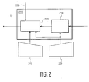
- the video processor 180 may contain a persistence module 200.
- An exemplary structure and operation of the persistence module 200 will be explained in greater detail with regard to FIG. 2 .
- the display 190 may generate a plurality of diagnostic ultrasonic images 500, which will be explained in association with FIGs. 5A-5C and FIGs. 6A and 6B .
- the diagnostic processor 135 may be configured with a method for performing a diagnostic analysis 800, which will be explained in association with the flowchart of FIG. 8 .
- the transducer 110 may be electrically coupled to the RF switch 120.
- the RF switch 120 may be configured as shown with a transmit input coupled from the transmit controller 130 and a transducer port electrically coupled to the transducer 110.
- the output of the RF switch 120 may be electrically coupled to an ADC 142 for digital conversion before further processing by the time gain control amplifier 144.
- the time gain control amplifier 144 may be coupled to a beamfomier 150.
- the beamformer 150 may be coupled to the RF filter 160.
- the RF filter 160 may be further coupled to a signal processor 170 before further signal processing in the video processor 180.
- the video processor 180 may then be configured to supply an input signal to the display 190.
- the system controller 140 may be coupled to the transmit controller 130, the ADC 142, the RF filter 160, and both the signal processor 170 and the video processor 180 to provide necessary timing signals to each of the various devices.
- the system controller 140 may be communicatively coupled with the patient interface 115 and the operator interface 125. It will be appreciated that the patient interface 115 may provide a number of pertinent parameters to the system controller 140. For example, the patient interface 115 may supply the system controller 140 with data indicative of a patient's breathing cycle, the patient's blood pressure, the patient's heart beat (e.g., electrocardiogram related data), as well as other patient parameters that may be useful in diagnosing a number of patient conditions.
- data indicative of a patient's breathing cycle the patient's blood pressure
- the patient's heart beat e.g., electrocardiogram related data
- the system controller 140 may comprise a general-purpose processor, a microprocessor, one or more application-specific integrated circuits (ASICs), a plurality of suitably configured logic gates, and other well known electrical configurations comprised of discrete elements both individually and in various combinations to coordinate the overall operation of the UCATI system 100.
- the system controller 140 may include one or more computers, memory devices, and other hardware and software components for coordinating the overall operation of the UCATI system 100.
- system controller 140 may include software, which comprises an ordered listing of executable instructions for implementing logical functions, which can be embodied in any computer-readable medium for use by or in connection with an instruction execution system, apparatus, or device, such as a computer-based system, processor-containing system, or other system that can fetch the instructions from the instruction execution system, apparatus, or device and execute the instructions.
- the computer readable medium can be, for instance, an electronic, magnetic, optical, electromagnetic, infrared, or semiconductor system, apparatus, device, or propagation medium.
- the other processors within the UCATI 100 may include one or more general-purpose processors, one or more ASICs, suitably configured logic gates, computers, memory devices, and other like hardware with associated software components for coordinating the overall operation of the particular designated functions associated with the particular processor 135, 170, 130, etc.
- these processors 135, 170, 180, and other devices may include software modules of their own, which comprise an ordered listing of executable instructions for implementing logical functions that can be embodied in any computer-readable medium.
- the RF switch 120 isolates the transmit controller 130 of the UCATI system 100 from the ultrasonic response receiving and processing sections comprising the remaining elements illustrated in FIG. 1 .
- the system architecture illustrated in FIG. 1 provides an electronic transmit signal generated within the transmit controller 130 that is converted to one or more ultrasonic pressure waves herein illustrated by ultrasound transmit pulses 105.
- ultrasound transmit pulses 105 encounter a tissue layer 103 that is receptive to ultrasound insonification the multiple transmit events or ultrasound transmit pulses 105 penetrate the tissue 103.
- the multiple ultrasound transmit pulses 105 will reach an internal target 101.
- tissue boundaries or intersections between tissues with different ultrasonic impedances will develop ultrasonic responses at harmonics of the fundamental frequency of the multiple ultrasound lines 105.
- such harmonic responses may be depicted by ultrasonic reflections 107.
- tissue 103 insonified with ultrasonic waves develops harmonic responses because the compressional portion of the insonified waveforms travels faster than the rarefactional portions. The different rates of travel of the compressional and the rarefactional portions of a waveform causes the wave to distort producing an harmonic signal which is reflected or scattered back through the various tissue boundaries.
- FIG. 1 illustrates only a second harmonic response to the incident multiple ultrasound transmit pulses 105 impinging the internal target 101 within the tissue 103, other harmonic responses may also observed.
- subharmonic, harmonic, and ultraharmonic responses may be created at the tissue boundary between the tissue 103 and the internal target 101.
- the internal target 101 alone will produce harmonic responses at integer multiples of the fundamental frequency.
- Various contrast agents on the other hand, have been shown to produce subharmonic, harmonic, and ultraharmonic responses.
- subharmonic and ultrahannonic responses may be designated as non-integer harmonic responses less than and greater than a fundamental or transmit frequency, respectively.
- Those ultrasonic reflections 107 of a magnitude that exceeds the attenuation effects from traversing tissue layer 103 may be monitored and converted into an electrical signal by the combination of the RF switch 120 and transducer 110.
- the electrical representation of the ultrasonic reflections 107 may be received at the ADC 142 where they are converted into a digital signal.
- the time gain control amplifier 144 coupled to the output of the ADC 142 may be configured to adjust amplification in relation to the total time a particular ultrasound reflection 105 needed to traverse the tissue layer 103. In this way, response signals from one or more internal targets 101 will be gain corrected so that ultrasonic reflections 107 generated from relatively shallow objects do not overwhelm (in magnitude) ultrasonic reflections 107 generated from insonified objects further removed from the transducer 110.
- the output of the time gain control amplifier 144 may be beamformed, filtered and demodulated via beamformer 150, the RF filter 160, and the signal processor 170.
- the processed response signal may then be forwarded to the video processor 180.
- the video version of the response signal may then be forwarded to display 190 where the response signal image may be viewed on a frame by frame basis.
- a frame of data includes any collection of data associated with a plurality of scan lines and any of various coordinate systems.
- the signal processor 170 may take the form of a B-mode processor, a Doppler processor, or a Doppler processor may be included in a parallel signal-processing path with a B-mode processor.
- a video recording device or other similar recording device such as but not limited to, an electrical connection (electronic) having one or more wires, a portable computer diskette (magnetic), a fixed or hard disk drive device (magnetic), a random access memory (RAM) (electronic), a read-only memory (ROM) (electronic), an erasable programmable read-only memory (EPROM or Flash memory) (electronic), an optical fiber (optical), and a portable compact disc read-only memory (CDROM) (optical) may be associated with the UCATI system 100 to record diagnostic data for post observation evaluation of the data.
- the computer-readable data storage medium could even be paper or another suitable medium upon which the data is printed, as the data is electronically captured by the UCATI system 100.
- triggering is used to coordinate the acquisition of multiple frames of ultrasonic response information.
- the system controller 140 may be configured to coordinate the operation of the transmit controller 130, the RF switch 120, and the various components along the ultrasound signal processing path in order to acquire multiple image frames.
- the system controller 140 may cause the acquisition of one or more frames of data.
- One trigger condition may be derived from information received from an ECG monitor (not shown) in communication with the patient interface 115.
- the trigger condition may be coordinated with a trigger derived from a patient's breathing cycle, an external timer, or some other trigger indication.
- the trigger condition is selectable by a UCATI system 100 user/operator and monitored by the system controller 140. The selection of one or more trigger inputs may be made via the operator interface 125.
- an ECG signal threshold may be set and the output from an ECG associated with the patient interface 115 may be compared to the ECG signal threshold, such as to identify peak systole.
- One or more thresholds or trigger points throughout a cardiac cycle may be identified as triggering thresholds and compared to the ECG signal.
- the system controller 140 may be configured to coordinate the acquisition and processing of one or more frames of data. It will be appreciated that one or more frames of data may be acquired and processed in response to the same or different trigger conditions.
- a patient's peak systole as sensed by an ECG or other similar device may comprise a first trigger input with a peak in a patient's breathing cycle (e.g., a signal derived from a patient exhaling) comprising a second trigger input.
- a first trigger input with a peak in a patient's breathing cycle (e.g., a signal derived from a patient exhaling) comprising a second trigger input.
- a peak in a patient's breathing cycle e.g., a signal derived from a patient exhaling
- Ultrasound imaging systems such as the UCATI system 100 may be operated in a real-time imaging mode that produces real-time moving images of insonified tissues. These moving images are acquired as discrete static images, but at a high enough frame rate (e.g., 20-30 frames/sec.) to produce the illusion of a continuously moving image.
- a high enough frame rate e.g. 20-30 frames/sec.
- multiple frames may be repetitively generated in accordance with one or more ultrasound transmit and triggering scenarios.
- the UCATI system 100 may remain quiescent between acquisition of successive triggered frames, neither transmitting nor receiving.
- the image display may remain static during quiescent periods, showing the last triggered frame.
- the diagnostic processor 135 contains one or more diagnostic algorithms configured to receive various image data from the video processor 180 to generate one or more diagnostic results. As illustrated in FIG. 1 , the system controller 140 may provide the signal path for the various image data to the diagnostic processor 135. For example, the diagnostic processor 135 may receive image data via the video processor 180 and operator inputs via the operator interface 125 indicative of a particular blood vessel of interest. Certain image data will provide an indication of the relative position of the vessel's wall as it may appear in a two-dimensional cross-sectional like view. In addition, Doppler mode (i.e., phase shift) information derived from contrast agent laden blood flowing through the vessel and or the blood cells alone may provide an indication of blood flow velocity.
- Doppler mode i.e., phase shift
- the vessel wall measurements and the Doppler information may be used by the diagnostic processor 135 to generate one or more outputs indicative of the relative health of the vessel and the tissues and or organs supplied by the vessel.
- the diagnostic processor 135 may generate one or more signal traces, image displays, data tables, and the like as a means for communicating diagnostic results.
- the system controller 140 and/or the video processor 180 may be configured to overlay the various diagnostic processor generated results with the ultrasonically processed tissue images.
- the persistence module 200 may comprise a frame processor/frame memory device 210 and a persistence controller 220.
- the frame processor/frame memory 210 may be configured to receive image-processing data from a signal processor (e.g ., the signal processor 170 ( FIG. 1 ).
- a frame-rate control signal 205 which may be provided by the system controller 140 ( FIG.1 ) the frame processor/frame memory 210 may be configured to supply image data to the persistence controller 220.
- the persistence controller 220 may receive a first input comprising the frame-rate control signal 205 and a second input comprising a persistence rate control input signal 215.
- the frame-rate control input and persistence-rate control input signals 205, 215 may be user selectable via appropriately configured user controls associated with the operator interface 125 ( FIG. 1 ).
- the frame-rate control input and persistence-rate control input signals 205, 215 may be driven by standard test diagnostic scenarios that may be stored or programmed in a software module residing in or associated with the system controller 140 ( FIG. 1 ).
- the persistence controller 220 may generate a video storage device/video display input signal in response to the frame data supplied by the frame processor/frame memory 210 and the frame rate control input and persistence rate control input signals 205, 215.
- a persistence actuator input signal 225 is also provided to the persistence controller 220. As shown in FIG. 2 , the persistence actuator input signal 225 may be supplied from the system controller 140 ( FIG. 1 ).
- successive frames of signal processed information are applied to the persistence module 200, which performs a suitable temporal filtering of the successive frames on a pixel by pixel basis during those times that the persistence actuator input signal 225 is enabled. Conversely, the persistence module 200 bypasses temporal filtering of the successive frames during those times that the persistence actuator input signal 225 is disabled.
- the persistence actuator input signal 225 selects an appropriate temporal filter and/or appropriate temporal filtering scheme in accordance with an operator selected diagnostic scenario.
- the method for synchronized persistence filtering 300 may begin as shown with step 302, herein labeled, "Start.”
- the method for synchronized persistence filtering 300 may introduce one or more ultrasound contrast agents suited for imaging blood flow dynamics or other fluid dynamics within a patient under observation.
- the method for synchronized persistence filtering 300 may perform step 306, where the patient may be insonified with a plurality of ultrasound transmit waves. It will be appreciated that this initial insonification of the tissue or tissues of interest may be performed with a plurality of transmit pulses or waves characterized by parameters suited for imaging of the contrast agent and the surrounding tissues without modifying or destroying the contrast agents.
- the method for synchronized persistence filtering 300 may continue to insonify the tissue or tissues of interest to permit the operator to properly orient the patient and the transducer 110 as illustrated in step 308 to identify an organ or structure within an organ that is of interest for further diagnosis and observation.
- the method for synchronized persistence filtering 300 may be configured to eliminate persistence or temporal filtering concurrently with the application of a contrast agent destruction transmit sequence.
- the method for synchronized persistence filtering 300 may be configured to eliminate persistence filtering and apply the contrast agent destruction sequence for a predetermined number of imaging frames given the present frame processing rate.
- the method for synchronized persistence filtering 300 may proceed by performing step 312, where as illustrated persistence filtering may applied along with a transmit sequence that permits imaging of the contrast agent and the surrounding tissues without modifying or destroying the contrast agents.
- the method for synchronized persistence filtering 300 applies the same transmit sequence that was applied in step 306. It will be appreciated that in alternative embodiments a modified-transmit sequence may be applied.
- the method for synchronized persistence filtering 300 may record contrast agent intensity over time.
- Another technique that may be applied by the UCATI system 100 of FIG. 1 to inhibit the inclusion of frames having a high-intensity echo signal resets the contents of the temporal filter in persistence module 200 immediately preceding the first frame after the high-intensity sequence. In this way, the persisted frames contain echo signals only from post high-intensity frames.
- data reflective of contrast agent intensity over time may be combined with data reflective of the surrounding tissue structures to perform one or more diagnostic tests without suffering from the adverse affects of continuously applying a persistence filtering scheme to the image data.
- the method for synchronized persistence filtering 300 may buffer a plurality of data points over time reflective of the contrast agent re-perfusion of the tissue or tissues of interest as new unmodified contrast agent traverses the image.
- FIGs. 4A and 4B present a cross-sectional view of a human heart that may be observed by the UCATI system 100 of FIG. 1 .
- the heart 400 comprises a right and left atrium 402, 406 and a right and left ventricle 404, 408 encompassed by a myocardial tissue layer 405, with a tricuspid valve 410 separating the right atrium 402 from the right ventricle 404 and a mitral valve 440 separating the left atrium 406 from the left ventricle 408.
- a pulmonary valve 420 separates the right ventricle 404 from the pulmonary arteries 417 and an aortic valve 430 separates the left ventricle 408 from the aorta 415.
- a superior and inferior vena cava 411,413 return blood from the body to the right atrium 402 and pulmonary veins 419 return blood from the lungs (not shown) to the left atrium 406.
- FIG. 4B illustrates blood flow into, through, and from the heart 400'.
- blood from the body flows into the right atrium 402 via the inferior and the superior vena cava 413, 411 respectively.
- the tricuspid valve 410 opens, blood from the right atrium 402 flows past the tricuspid valve 410 into the right ventricle 404.
- the pulmonary valve 420 opens, blood in the right ventricle 404 is expelled from the heart and transferred to the right and left lungs (not shown) via the pulmonary arteries 417.
- the blood After the blood has been oxygenated in the right and left lungs (not shown), the blood is returned via the pulmonary veins 419 to the left atrium 406. After the mitral valve 440 opens, the oxygenated blood flows from the left atrium 406 to the left ventricle 408. Upon opening of the aortic valve 430, blood is expelled from the heart 400' by the left ventricle 408 and is carried by the aorta 415 on its way to the various parts of the body.
- a contrast agent When a contrast agent has been introduced into the bloodstream, a significant quantity of the contrast agent will be contained within the right and left atrium 402, 406 respectively, as well as, the right and left ventricles 404, 408 of the heart 400', while only a relatively smaller quantity of contrast agent will enter tissues or organs by way of capillaries within the circulatory system.
- the introduction of a contrast agent into the bloodstream followed by ultrasound insonification permits imaging of the blood flow through the heart for a period of time until the contrast agent has perfused the myocardial tissue layer 405.
- FIG. 5A illustrates the travel of a contrast agent infused into the bloodstream of a patient via an intravenous injection site 520 through an organ of interest 550.
- operation of the heart 400, 400' promotes blood circulation from the intravenous injection site 520 in a clockwise direction across the structures illustrated in FIG. 5A .
- blood traverses the right ventricle 404 on its way to the lungs 510.
- Blood is returned from the lungs 510 to the heart 400 (not shown in total) where it passes from the left ventricle 408 out to the various parts of the body through the various arteries of the body 525 (one shown for simplicity of illustration).
- the perfusion rate into the organ of interest 550 can be used to evaluate the viability of blood flow through the organ of interest 550 or to identify the location of a stenosis.
- the rate of expected perfusion across the various capillaries (not shown) of the organ of interest 550' will be reduced across the entire organ of interest 550'.
- the rate of expected perfusion will be reduced across a small portion of the organ of interest 550".
- ultrasound image 600 of FIG. 6A may comprise alphanumeric information in the form of patient identifiers 602, date and time identifiers 604 and scanning parameters 606.
- the ultrasound image 600 may comprise a real-time ultrasound image display 610 of a structure in a body such as a portion of the circulatory system 620.
- a clinical technician may ascertain and locate tissues of interest within an image frame using a real-time image.
- the image is created from echoes returned from the non-destructive ultrasonic imaging of one or more contrast agents and/or tissue structures within the patient.
- FIG. 6B presents an ultrasound image 600' representing a snapshot of a real-time ultrasound image display 610' of a portion of the circulatory system 620' after introduction of one or more contrast agents in the patient's bloodstream.
- the non-linear response from the one or more contrast agents can have a significant effect on the contrast agent to tissue ratio in the ultrasound image 610' showing a portion of the circulatory system 620'.
- real-time contrast agent images may be acquired at any phase of the heart cycle, not just when the heart is predominately at rest. While the aforementioned real-time imagery of the heart is especially useful in cardiology, variations of this method may prove useful in radiology diagnostics where anatomical structures are more stationary.
- FIG. 7A illustrates an exemplary ultrasonic transmit power trace over time that may be generated by the transmit controller 130 under the direction of the system controller 140 of the UCATI system 100 of FIG. 1 .
- an ultrasonic transmit power trace 700 may comprise a first transmit portion 710a characterized by a plurality of individual ultrasonic transmit pulses 105 ( FIG. 1 ) having a relatively low mechanical index (MI) and a second portion 720 characterized by a plurality of individual ultrasonic pulses 105 ( FIG. 1 ) having a relatively high MI.
- MI mechanical index
- a relatively low MI may vary with regard to the contrast agent or agents selected for introduction into the patient.
- this first transmit portion 710a it is desirable to transmit at a MI that results in a relatively stable ( i.e., non-destructive) response from a substantial portion of the contrast agent imaged.
- the second transmit portion 720 it is desirable to destroy the contrast agent present in the region of interest to enable observation of blood flow parameters over time as contrast agent rich blood re-perfuses the region of interest.
- the second transmit portion 720 representing the application of a destructive transmit sequence may be operator initiated after an operator has identified that a particular region of interest is receiving a sufficient amount of contrast agent over time to adequately image the circulatory structures. It is further significant to note that once the operator has selected a mode characterized by the repetitive application of an ultrasonic transmit destruction sequence, the ultrasonic transmit power trace 700 may be coordinated ( e.g ., adjusted in time, frequency, and/or in MI) by the system controller 140 and other various components of the UCATI system 100 ( FIG. 1 ) such that a re-perfusion study over time is optimized.
- the exemplary electrocardiogram signal trace 725 illustrated in FIG. 7B may be used to provide a triggering input to the system controller 140.
- the system controller 140 may be configured to respond to one or more portions of the ECG trace (e.g., the P, Q, R, S and T waves) and or other patient parameters as previously described.
- the relative positioning of the ECG trace and or any other exemplary triggering input, for that matter, may be adjusted with respect to the ultrasonic transmit power trace 700.
- the ultrasonic transmit power trace 700 in accordance with the present invention may be configured in such a manner that it provides a sufficiently long ultrasonic observation period (e.g., the first transmit portion 710a) that follows a contrast agent destructive sequence (e.g., the second transmit portion 720) such that the structure under observation reaches a steady-state intensity of contrast agent perfusion over time.
- a sufficiently long ultrasonic observation period e.g., the first transmit portion 710a
- a contrast agent destructive sequence e.g., the second transmit portion 720
- the average or total intensity of the contrast agent re-perfusing the region under observation increases with longer periods between destructive sequences.
- the slope of the intensity over time as indicated by line segment AB 760 for time segments shorter than that associated with the onset of the maximum intensity contrast agent intensity is an estimate of the velocity of the contrast agent in the tissues under observation.
- a mathematical combination of the contrast agent velocity and the area of the structure under observation may be used to generate a measure of blood flow volume.
- the average flow rate and the average volume may be stored and or applied to various diagnosis algorithms to determine a patient's relative health status.
- FIG. 8 further illustrates a method for performing a blood flow rate and blood volume analysis that may be practiced by the ultrasonic imaging system of FIG. 1 .
- the method for diagnostic analysis 800 may begin as shown with step 802, herein labeled, "Start.”
- the method for diagnostic analysis 800 may determine the geometry of an object under test. For example, if a particular artery supplying a portion of the heart muscle is of interest, the method for diagnostic analysis 800 may identify the average distance between the walls of the artery of interest over the image display. It will be appreciated that the distance between the walls may be used to derive both a cross-sectional area over portions of the artery as well as a volumetric measure of the blood which may be supplied by the artery. It will be further appreciated that the blood volume measurement may be coupled with 02 saturation measurements to determine if that particular portion of the heart muscle is receiving a sufficient supply of oxygen over time.
- the method for diagnostic analysis 800 may retrieve stored perfusion trace information as indicated in step 806. It will be appreciated that in an alternative embodiment perfusion trace infonnation may be provided and buffered within the diagnostic processor 135 ( FIG. 1 ). As illustrated in step 808, the method for diagnostic analysis 800 may be configured to detennine the slope of the perfusion trace to determine the velocity of the contrast agent within the blood in the artery of interest. In accordance with a preferred embodiment, the method for diagnostic analysis 800 is configured to provide the flow rate infonnation to an output device as illustrated in step 810. After having derived a flow rate measurement, the method for diagnostic analysis 800 may be configured to detennine a steady-state maximum intensity from the perfusion trace data as indicated in step 812. Next, the method for diagnostic analysis 800 may be configured to provide the volumetric measurement to an output device as illustrated in step 814. Last, the method for diagnostic analysis 800 may tenninate as illustrated in step 816, herein labeled, "Stop.”
- the flow rate and blood volume measurements may be buffered in a suitable memory device.
- the buffered data may then be mathematically combined over a suitable time period.
Landscapes
- Health & Medical Sciences (AREA)
- Physics & Mathematics (AREA)
- Engineering & Computer Science (AREA)
- Life Sciences & Earth Sciences (AREA)
- Radar, Positioning & Navigation (AREA)
- Remote Sensing (AREA)
- Pathology (AREA)
- Heart & Thoracic Surgery (AREA)
- Nonlinear Science (AREA)
- Computer Networks & Wireless Communication (AREA)
- Biophysics (AREA)
- Nuclear Medicine, Radiotherapy & Molecular Imaging (AREA)
- Veterinary Medicine (AREA)
- Radiology & Medical Imaging (AREA)
- Biomedical Technology (AREA)
- General Physics & Mathematics (AREA)
- Medical Informatics (AREA)
- Molecular Biology (AREA)
- Surgery (AREA)
- Animal Behavior & Ethology (AREA)
- General Health & Medical Sciences (AREA)
- Public Health (AREA)
- Acoustics & Sound (AREA)
- Hematology (AREA)
- Physiology (AREA)
- Ultra Sonic Daignosis Equipment (AREA)
Claims (21)
- Verfahren zur Beobachtung einer Ultraschallantwort eines Kontrastmittels in für die Bildgebung vorgesehenem Gewebe, wobei das Verfahren Folgendes umfasst:- Beschallen (306) von Gewebe (103) mit einem Wandler (110), der durch ein erstes Ultraschallsendesignal erregt wird, das geeignet ist, um eine Echtzeitbeobachtung des von Kontrastmittel durchströmten Gewebes (103) zu ermöglichen; und- Modifizieren (310) von mindestens einem Ultraschallsendesignalparameter, um ein zweites Ultraschallsendesignal zu erzeugen, wobei ein wesentlicher Anteil des in dem beschallten Gewebe (103) vorhandenen Kontrastmittels zerstört wird;gekennzeichnet durch den Schritt des- Betätigens (312) eines Persistenzfilters in Reaktion auf das zweite Ultraschallsendesignal, wobei aufeinanderfolgende Einzelbilder, die während der Zuführung des zweiten Ultraschallsendesignals erfasst wurden, zu den persistenzgefilterten Ergebnissen beitragen.
- Verfahren nach Anspruch 1, das weiterhin Folgendes umfasst:- erneutes Zuführen des ersten Ultraschallsendesignals, um eine Echtzeitbeobachtung von Kontrastmittel-Reperfusion durch das für die Bildgebung vorgesehene Gewebe (103) zu erlauben; und- Betätigen des Persistenzfilters in Reaktion auf die erneute Zuführung des ersten Ultraschallsendesignals.
- Verfahren nach Anspruch 1, wobei das erste Ultraschallsendesignal einen ausgewählten mechanischen Index (MI) umfasst, wobei das mindestens eine Kontrastmittel, das in das Gewebe (103) eingeführt wurde, über die Zeit im Wesentlichen unverändert bleibt.
- Verfahren nach Anspruch 1, wobei das erste Ultraschallsendesignal eine Frequenz über ca. 1,5 MHz umfasst.
- Verfahren nach Anspruch 1 wobei das zweite Ultraschallsendesignal einen ausgewählten mechanischen Index (MI) umfasst, wobei das mindestens eine in das Gewebe (103) eingeführte Kontrastmittel über die Zeit im Wesentlichen zerstört wird.
- Verfahren nach Anspruch 1, wobei das zweite Ultraschallsendesignal eine Frequenz unter ca. 1,5 MHz umfasst.
- Verfahren nach Anspruch 1, wobei der Schritt des Modifizierens (310) in Reaktion auf ein Auslösesignal durchgeführt wird.
- Verfahren nach Anspruch 1, wobei der Schritt des Betätigens (312) das Deaktivieren des Persistenzfilters umfasst.
- Verfahren nach Anspruch 1 wobei der Schritt des Betätigens (312) das Zurücksetzen des Persistenzfilters umfasst.
- Verfahren nach Anspruch 2, wobei der Schritt des Betätigens des Persistenzfilters in Reaktion auf die erneute Zuführung des ersten Ultraschallsendesignals das Aktivieren des Persistenzfilters umfasst.
- Verfahren nach Anspruch 7, wobei das Auslösesignal in Reaktion auf mindestens einen vom Patienten abgeleiteten Parameter erzeugt wird.
- Verfahren nach Anspruch 11, wobei der mindestens eine vom Patienten abgeleitete Parameter eine Elektrokardiogramm-Wellenform ist.
- Ultraschallbildgebungssystem (100) zur harmonischen Bildgebung von mindestens einem Kontrastmittel und Gewebe (103) in einem Patienten, wobei das System (100) Folgendes umfasst:- Mittel (110) zum Beschallen eines mit Kontrastmittel durchströmten interessierende Gewebes (103) mit einer Vielzahl von Ultraschallimpulsen (105), wobei das mindestens eine Kontrastmittel über die Zeit beobachtet werden kann; und- Mittel (130, 140) zum kontrollierbaren Modifizieren von mindestens einem Ultraschallsendeimpuls (105), wobei das mindestens eine Kontrastmittel derartig modifiziert wird, dass das mindestens eine Kontrastmittel nicht mehr länger in dem interessierende Gewebe (103) beobachtet werden kann;dadurch gekennzeichnet, dass das System (100) weiterhin Folgendes umfasst:- Mittel (200) zum Entfernen von Resteffekten eines Persistenzfilters aus einem Ultraschallantwort-Verarbeitungspfad in Reaktion auf das Modifizierungsmittel (130, 140), so dass die Persistenzfilterung nicht während einer Periode angewandt wird, die gleichzeitig mit der Zuführung des modifizierten mindestens einen Ultraschallsendeimpulses (105) vorliegt.
- System nach Anspruch 13, wobei das Mittel (200) zum Entfernen konfiguriert ist, um zu einem ersten Einzelbild gehörende Daten durch Daten zu ersetzen, die zu einem nachfolgenden Einzelbild gehören.
- System nach Anspruch 13, wobei das Mittel (200) zum Entfernen konfiguriert ist, um zu einem ersten Einzelbild gehörende Daten durch Daten zu ersetzen, die zu einem unmittelbar vorhergehenden Einzelbild gehören.
- System nach Anspruch 13, das weiterhin Mittel (500) zum Diagnostizieren von mindestens einem Blutströmungsparameter umfasst.
- System nach Anspruch 16, wobei das Diagnosemittel (500) konfiguriert ist, um die Reperfusion des mindestens einen Kontrastmittels in dem Gewebe (103) des Patienten zu überwachen.
- System nach Anspruch 13, das Folgendes umfasst:- einen Einzelbildspeicher, der konfiguriert ist, um vorübergehend eine Vielzahl von Einzelbildern zu speichern;- einen Einzelbildprozessor (210), der mit dem Einzelbildspeicher gekoppelt ist, wobei der Einzelbildprozessor (210) konfiguriert ist, um eine Ausgabe mit Bilddaten auf einer Pixelbasis zu erzeugen;- eine Persistenzbetätigungselement, das auf mindestens ein Ultraschallsendesignal reagiert; und- eine Persistenzsteuereinheit (220), die konfiguriert ist, um die Ausgabe des Einzelbildprozessors zu empfangen, wobei die Persistenzsteuereinheit (220) konfiguriert ist, um Bilddaten auf einer Pixelbasis aus vorhergehenden Einzelbildern in Reaktion auf das Persistenzbetätigungselement zu kombinieren.
- System nach Anspruch 18, wobei das Persistenzbetätigungselement konfiguriert ist, um die Persistenzsteuereinheit (220) in Reaktion auf das mindestens eine Ultraschallsendesignal zu deaktivieren, wenn das Sendesignal derartig konfiguriert ist, dass es das mindestens eine Kontrastmittel in dem Gewebe (103) im Wesentlichen zerstören wird.
- System nach Anspruch 19, wobei das Persistenzbetätigungselement konfiguriert ist, um die Persistenzsteuereinheit (220) für eine vorgegebene Anzahl von Einzelbildern zu deaktivieren.
- System nach Anspruch 19, wobei das Persistenzbetätigungselement konfiguriert ist, um die Persistenzsteuereinheit (220) für eine vorgegebene Anzahl von Einzelbildern zurückzusetzen.
Applications Claiming Priority (3)
| Application Number | Priority Date | Filing Date | Title |
|---|---|---|---|
| US10/174,282 US6612989B1 (en) | 2002-06-18 | 2002-06-18 | System and method for synchronized persistence with contrast agent imaging |
| US174282 | 2002-06-18 | ||
| PCT/IB2003/002497 WO2003105691A1 (en) | 2002-06-18 | 2003-06-04 | Contrast agent imaging with synchronized persistence |
Publications (2)
| Publication Number | Publication Date |
|---|---|
| EP1517636A1 EP1517636A1 (de) | 2005-03-30 |
| EP1517636B1 true EP1517636B1 (de) | 2015-09-16 |
Family
ID=27765773
Family Applications (1)
| Application Number | Title | Priority Date | Filing Date |
|---|---|---|---|
| EP03732849.9A Expired - Lifetime EP1517636B1 (de) | 2002-06-18 | 2003-06-04 | Kontrastmittelunterstützte bildgebung mit synchronisierter persistenz |
Country Status (6)
| Country | Link |
|---|---|
| US (1) | US6612989B1 (de) |
| EP (1) | EP1517636B1 (de) |
| JP (1) | JP2005529672A (de) |
| CN (1) | CN100518657C (de) |
| AU (1) | AU2003239268A1 (de) |
| WO (1) | WO2003105691A1 (de) |
Families Citing this family (26)
| Publication number | Priority date | Publication date | Assignee | Title |
|---|---|---|---|---|
| US6554774B1 (en) * | 2000-03-23 | 2003-04-29 | Tensys Medical, Inc. | Method and apparatus for assessing hemodynamic properties within the circulatory system of a living subject |
| GB0228960D0 (en) * | 2002-12-11 | 2003-01-15 | Mirada Solutions Ltd | Improvements in or relating to processing systems |
| JP4373699B2 (ja) | 2003-04-28 | 2009-11-25 | 株式会社東芝 | 超音波診断装置 |
| JP3964364B2 (ja) * | 2003-07-22 | 2007-08-22 | ジーイー・メディカル・システムズ・グローバル・テクノロジー・カンパニー・エルエルシー | 超音波診断装置 |
| US7591788B2 (en) * | 2003-08-19 | 2009-09-22 | Siemens Medical Solutions Usa, Inc. | Adaptive contrast agent medical imaging |
| JP4801912B2 (ja) * | 2004-03-24 | 2011-10-26 | 株式会社東芝 | 超音波診断装置 |
| JP4805254B2 (ja) | 2004-04-20 | 2011-11-02 | ビジュアルソニックス インコーポレイテッド | 配列された超音波トランスデューサ |
| US20060030777A1 (en) * | 2004-07-30 | 2006-02-09 | Liang David H | T-statistic method for suppressing artifacts in blood vessel ultrasonic imaging |
| WO2007022505A2 (en) * | 2005-08-19 | 2007-02-22 | Visualsonics Inc. | Systems and methods for capture and display of blood pressure and ultrasound data |
| US7901358B2 (en) | 2005-11-02 | 2011-03-08 | Visualsonics Inc. | High frequency array ultrasound system |
| JP2008198268A (ja) * | 2007-02-09 | 2008-08-28 | Hitachi-Lg Data Storage Inc | 光ディスク装置、及び、その自己診断制御方法 |
| US20080214934A1 (en) * | 2007-03-02 | 2008-09-04 | Siemens Medical Solutions Usa, Inc. | Inter-frame processing for contrast agent enhanced medical diagnostic ultrasound imaging |
| JP2008245891A (ja) * | 2007-03-30 | 2008-10-16 | Ge Medical Systems Global Technology Co Llc | 超音波造影撮影方法および超音波診断装置 |
| US9184369B2 (en) | 2008-09-18 | 2015-11-10 | Fujifilm Sonosite, Inc. | Methods for manufacturing ultrasound transducers and other components |
| US9173047B2 (en) | 2008-09-18 | 2015-10-27 | Fujifilm Sonosite, Inc. | Methods for manufacturing ultrasound transducers and other components |
| EP3309823B1 (de) * | 2008-09-18 | 2020-02-12 | FUJIFILM SonoSite, Inc. | Ultraschallwandler |
| US8192364B2 (en) * | 2009-06-10 | 2012-06-05 | Mayo Foundation For Medical Education And Research | Method for assessing vascular disease by quantitatively measuring vaso vasorum |
| WO2011045734A1 (en) * | 2009-10-16 | 2011-04-21 | Koninklijke Philips Electronics N.V. | Photoacoustic contrast agent based active ultrasound imaging |
| US8396276B2 (en) * | 2009-10-26 | 2013-03-12 | Boston Scientific Scimed, Inc. | Systems and methods for performing an image-based gating procedure during an IVUS imaging procedure |
| JP5414581B2 (ja) * | 2010-03-12 | 2014-02-12 | 株式会社東芝 | 超音波診断装置 |
| US20130274590A1 (en) * | 2012-04-17 | 2013-10-17 | Vincent Auboiroux | Method and apparatus for generating a signal indicative of motion of a subject in a magnetic resonance apparatus |
| CN102697522B (zh) * | 2012-06-01 | 2013-11-20 | 贝恩医疗设备(广州)有限公司 | 一种在线相对血容量检测装置及其检测方法 |
| JP6139186B2 (ja) * | 2013-03-11 | 2017-05-31 | 東芝メディカルシステムズ株式会社 | 超音波診断装置、画像処理装置及び画像処理プログラム |
| US10687781B2 (en) | 2013-03-15 | 2020-06-23 | Nilus Medical Llc | Hemodynamic monitoring device and methods of using same |
| US10376240B2 (en) | 2015-05-15 | 2019-08-13 | Siemens Medical Solutions Usa, Inc. | Contrast agent sensitive medical ultrasound imaging |
| CA3184116A1 (en) | 2020-07-01 | 2022-01-06 | Scott A. Miller | Acousto-optic harmonic imaging with optical sensors |
Family Cites Families (10)
| Publication number | Priority date | Publication date | Assignee | Title |
|---|---|---|---|---|
| FR2593698A1 (fr) * | 1986-01-31 | 1987-08-07 | Labo Electronique Physique | Appareil d'examen de milieux en mouvement par echographie ultrasonore |
| US5410516A (en) | 1988-09-01 | 1995-04-25 | Schering Aktiengesellschaft | Ultrasonic processes and circuits for performing them |
| US5215094A (en) * | 1990-11-14 | 1993-06-01 | Advanced Technology Laboratories, Inc. | Ultrasonic flow velocity imaging systems with velocity image presistence |
| US5595179A (en) | 1995-05-02 | 1997-01-21 | Acuson Corporation | Adaptive persistence processing |
| US5833613A (en) | 1996-09-27 | 1998-11-10 | Advanced Technology Laboratories, Inc. | Ultrasonic diagnostic imaging with contrast agents |
| US5577505A (en) | 1996-02-06 | 1996-11-26 | Hewlett-Packard Company | Means for increasing sensitivity in non-linear ultrasound imaging systems |
| US5873830A (en) * | 1997-08-22 | 1999-02-23 | Acuson Corporation | Ultrasound imaging system and method for improving resolution and operation |
| US5971928A (en) * | 1998-11-02 | 1999-10-26 | Acuson Corporation | Diagnostic medical ultrasonic system and method for image subtraction |
| US6322505B1 (en) * | 1999-06-08 | 2001-11-27 | Acuson Corporation | Medical diagnostic ultrasound system and method for post processing |
| US6340348B1 (en) | 1999-07-02 | 2002-01-22 | Acuson Corporation | Contrast agent imaging with destruction pulses in diagnostic medical ultrasound |
-
2002
- 2002-06-18 US US10/174,282 patent/US6612989B1/en not_active Expired - Lifetime
-
2003
- 2003-06-04 AU AU2003239268A patent/AU2003239268A1/en not_active Abandoned
- 2003-06-04 EP EP03732849.9A patent/EP1517636B1/de not_active Expired - Lifetime
- 2003-06-04 CN CNB03814025XA patent/CN100518657C/zh not_active Expired - Fee Related
- 2003-06-04 WO PCT/IB2003/002497 patent/WO2003105691A1/en not_active Ceased
- 2003-06-04 JP JP2004512606A patent/JP2005529672A/ja not_active Withdrawn
Also Published As
| Publication number | Publication date |
|---|---|
| AU2003239268A1 (en) | 2003-12-31 |
| US6612989B1 (en) | 2003-09-02 |
| CN100518657C (zh) | 2009-07-29 |
| WO2003105691A1 (en) | 2003-12-24 |
| JP2005529672A (ja) | 2005-10-06 |
| CN1662180A (zh) | 2005-08-31 |
| EP1517636A1 (de) | 2005-03-30 |
Similar Documents
| Publication | Publication Date | Title |
|---|---|---|
| EP1517636B1 (de) | Kontrastmittelunterstützte bildgebung mit synchronisierter persistenz | |
| US6969353B2 (en) | Contrast-agent enhanced color-flow imaging | |
| US6827686B2 (en) | System and method for improved harmonic imaging | |
| JP4159122B2 (ja) | コントラスト剤を使用した超音波診断画像処理方法および該診断装置 | |
| US5846202A (en) | Ultrasound method and system for imaging | |
| EP0948931B1 (de) | Ultraschallabbildung mittels kodierter Anregung beim Senden und selektiver Filterung beim Empfang | |
| US6937883B2 (en) | System and method for generating gating signals for a magnetic resonance imaging system | |
| US7862511B2 (en) | Ultrasound imaging method and apparatus | |
| US6652463B2 (en) | System and method for non-linear detection of ultrasonic contrast agents at a fundamental frequency | |
| JPH08182680A (ja) | 超音波診断装置 | |
| JPH09201359A (ja) | 超音波診断装置 | |
| US20040064043A1 (en) | Continuous depth harmonic imaging using transmitted and nonlinearly generated second harmonics | |
| US8328724B2 (en) | Method for imaging intracavitary blood flow patterns | |
| JP3459304B2 (ja) | 超音波診断装置 | |
| EP1003051A2 (de) | Ultraschall- Bilderzeugungsgerät | |
| JP4574790B2 (ja) | 超音波診断装置及び超音波診断方法 | |
| US20050234340A1 (en) | Bolus control for contrast imaging with 3D | |
| CN100421627C (zh) | 超声波成像装置和超声波成像方法 | |
| Kirkhorn et al. | Three-stage approach to ultrasound contrast detection | |
| JP3746119B2 (ja) | 超音波診断装置 | |
| US20090124908A1 (en) | Method And Apparatus For Detecting Ultrasound Contrast Agents In Arterioles | |
| Schmitz | Biomedical Sonography | |
| JP2004160251A (ja) | 超音波診断装置 |
Legal Events
| Date | Code | Title | Description |
|---|---|---|---|
| PUAI | Public reference made under article 153(3) epc to a published international application that has entered the european phase |
Free format text: ORIGINAL CODE: 0009012 |
|
| 17P | Request for examination filed |
Effective date: 20050118 |
|
| AK | Designated contracting states |
Kind code of ref document: A1 Designated state(s): AT BE BG CH CY CZ DE DK EE ES FI FR GB GR HU IE IT LI LU MC NL PT RO SE SI SK TR |
|
| AX | Request for extension of the european patent |
Extension state: AL LT LV MK |
|
| DAX | Request for extension of the european patent (deleted) | ||
| RIN1 | Information on inventor provided before grant (corrected) |
Inventor name: BROCK-FISHER, GEORGE |
|
| 17Q | First examination report despatched |
Effective date: 20101020 |
|
| RAP1 | Party data changed (applicant data changed or rights of an application transferred) |
Owner name: KONINKLIJKE PHILIPS N.V. |
|
| GRAP | Despatch of communication of intention to grant a patent |
Free format text: ORIGINAL CODE: EPIDOSNIGR1 |
|
| RIC1 | Information provided on ipc code assigned before grant |
Ipc: A61B 5/0456 20060101ALN20150312BHEP Ipc: G01S 7/52 20060101ALI20150312BHEP Ipc: G01S 15/89 20060101ALI20150312BHEP Ipc: A61B 8/06 20060101ALI20150312BHEP Ipc: A61B 8/08 20060101ALI20150312BHEP Ipc: A61B 8/00 20060101AFI20150312BHEP |
|
| INTG | Intention to grant announced |
Effective date: 20150409 |
|
| RIN1 | Information on inventor provided before grant (corrected) |
Inventor name: BROCK-FISHER, GEORGE |
|
| GRAS | Grant fee paid |
Free format text: ORIGINAL CODE: EPIDOSNIGR3 |
|
| GRAA | (expected) grant |
Free format text: ORIGINAL CODE: 0009210 |
|
| AK | Designated contracting states |
Kind code of ref document: B1 Designated state(s): AT BE BG CH CY CZ DE DK EE ES FI FR GB GR HU IE IT LI LU MC NL PT RO SE SI SK TR |
|
| REG | Reference to a national code |
Ref country code: GB Ref legal event code: FG4D |
|
| REG | Reference to a national code |
Ref country code: CH Ref legal event code: EP |
|
| REG | Reference to a national code |
Ref country code: IE Ref legal event code: FG4D |
|
| REG | Reference to a national code |
Ref country code: AT Ref legal event code: REF Ref document number: 749125 Country of ref document: AT Kind code of ref document: T Effective date: 20151015 |
|
| REG | Reference to a national code |
Ref country code: DE Ref legal event code: R096 Ref document number: 60348050 Country of ref document: DE |
|
| REG | Reference to a national code |
Ref country code: NL Ref legal event code: MP Effective date: 20150916 |
|
| PG25 | Lapsed in a contracting state [announced via postgrant information from national office to epo] |
Ref country code: FI Free format text: LAPSE BECAUSE OF FAILURE TO SUBMIT A TRANSLATION OF THE DESCRIPTION OR TO PAY THE FEE WITHIN THE PRESCRIBED TIME-LIMIT Effective date: 20150916 Ref country code: GR Free format text: LAPSE BECAUSE OF FAILURE TO SUBMIT A TRANSLATION OF THE DESCRIPTION OR TO PAY THE FEE WITHIN THE PRESCRIBED TIME-LIMIT Effective date: 20151217 |
|
| REG | Reference to a national code |
Ref country code: AT Ref legal event code: MK05 Ref document number: 749125 Country of ref document: AT Kind code of ref document: T Effective date: 20150916 |
|
| PG25 | Lapsed in a contracting state [announced via postgrant information from national office to epo] |
Ref country code: SE Free format text: LAPSE BECAUSE OF FAILURE TO SUBMIT A TRANSLATION OF THE DESCRIPTION OR TO PAY THE FEE WITHIN THE PRESCRIBED TIME-LIMIT Effective date: 20150916 |
|
| PG25 | Lapsed in a contracting state [announced via postgrant information from national office to epo] |
Ref country code: NL Free format text: LAPSE BECAUSE OF FAILURE TO SUBMIT A TRANSLATION OF THE DESCRIPTION OR TO PAY THE FEE WITHIN THE PRESCRIBED TIME-LIMIT Effective date: 20150916 |
|
| PG25 | Lapsed in a contracting state [announced via postgrant information from national office to epo] |
Ref country code: EE Free format text: LAPSE BECAUSE OF FAILURE TO SUBMIT A TRANSLATION OF THE DESCRIPTION OR TO PAY THE FEE WITHIN THE PRESCRIBED TIME-LIMIT Effective date: 20150916 Ref country code: SK Free format text: LAPSE BECAUSE OF FAILURE TO SUBMIT A TRANSLATION OF THE DESCRIPTION OR TO PAY THE FEE WITHIN THE PRESCRIBED TIME-LIMIT Effective date: 20150916 Ref country code: CZ Free format text: LAPSE BECAUSE OF FAILURE TO SUBMIT A TRANSLATION OF THE DESCRIPTION OR TO PAY THE FEE WITHIN THE PRESCRIBED TIME-LIMIT Effective date: 20150916 Ref country code: ES Free format text: LAPSE BECAUSE OF FAILURE TO SUBMIT A TRANSLATION OF THE DESCRIPTION OR TO PAY THE FEE WITHIN THE PRESCRIBED TIME-LIMIT Effective date: 20150916 |
|
| PG25 | Lapsed in a contracting state [announced via postgrant information from national office to epo] |
Ref country code: RO Free format text: LAPSE BECAUSE OF FAILURE TO SUBMIT A TRANSLATION OF THE DESCRIPTION OR TO PAY THE FEE WITHIN THE PRESCRIBED TIME-LIMIT Effective date: 20150916 Ref country code: PT Free format text: LAPSE BECAUSE OF FAILURE TO SUBMIT A TRANSLATION OF THE DESCRIPTION OR TO PAY THE FEE WITHIN THE PRESCRIBED TIME-LIMIT Effective date: 20160118 Ref country code: AT Free format text: LAPSE BECAUSE OF FAILURE TO SUBMIT A TRANSLATION OF THE DESCRIPTION OR TO PAY THE FEE WITHIN THE PRESCRIBED TIME-LIMIT Effective date: 20150916 |
|
| REG | Reference to a national code |
Ref country code: DE Ref legal event code: R097 Ref document number: 60348050 Country of ref document: DE |
|
| REG | Reference to a national code |
Ref country code: FR Ref legal event code: PLFP Year of fee payment: 14 |
|
| PLBE | No opposition filed within time limit |
Free format text: ORIGINAL CODE: 0009261 |
|
| STAA | Information on the status of an ep patent application or granted ep patent |
Free format text: STATUS: NO OPPOSITION FILED WITHIN TIME LIMIT |
|
| 26N | No opposition filed |
Effective date: 20160617 |
|
| PG25 | Lapsed in a contracting state [announced via postgrant information from national office to epo] |
Ref country code: DK Free format text: LAPSE BECAUSE OF FAILURE TO SUBMIT A TRANSLATION OF THE DESCRIPTION OR TO PAY THE FEE WITHIN THE PRESCRIBED TIME-LIMIT Effective date: 20150916 |
|
| PG25 | Lapsed in a contracting state [announced via postgrant information from national office to epo] |
Ref country code: SI Free format text: LAPSE BECAUSE OF FAILURE TO SUBMIT A TRANSLATION OF THE DESCRIPTION OR TO PAY THE FEE WITHIN THE PRESCRIBED TIME-LIMIT Effective date: 20150916 |
|
| PG25 | Lapsed in a contracting state [announced via postgrant information from national office to epo] |
Ref country code: BE Free format text: LAPSE BECAUSE OF FAILURE TO SUBMIT A TRANSLATION OF THE DESCRIPTION OR TO PAY THE FEE WITHIN THE PRESCRIBED TIME-LIMIT Effective date: 20150916 |
|
| PG25 | Lapsed in a contracting state [announced via postgrant information from national office to epo] |
Ref country code: MC Free format text: LAPSE BECAUSE OF FAILURE TO SUBMIT A TRANSLATION OF THE DESCRIPTION OR TO PAY THE FEE WITHIN THE PRESCRIBED TIME-LIMIT Effective date: 20150916 |
|
| REG | Reference to a national code |
Ref country code: CH Ref legal event code: PL |
|
| GBPC | Gb: european patent ceased through non-payment of renewal fee |
Effective date: 20160604 |
|
| REG | Reference to a national code |
Ref country code: IE Ref legal event code: MM4A |
|
| PG25 | Lapsed in a contracting state [announced via postgrant information from national office to epo] |
Ref country code: LI Free format text: LAPSE BECAUSE OF NON-PAYMENT OF DUE FEES Effective date: 20160630 Ref country code: CH Free format text: LAPSE BECAUSE OF NON-PAYMENT OF DUE FEES Effective date: 20160630 |
|
| PG25 | Lapsed in a contracting state [announced via postgrant information from national office to epo] |
Ref country code: IE Free format text: LAPSE BECAUSE OF NON-PAYMENT OF DUE FEES Effective date: 20160604 Ref country code: GB Free format text: LAPSE BECAUSE OF NON-PAYMENT OF DUE FEES Effective date: 20160604 |
|
| REG | Reference to a national code |
Ref country code: FR Ref legal event code: PLFP Year of fee payment: 15 |
|
| PG25 | Lapsed in a contracting state [announced via postgrant information from national office to epo] |
Ref country code: CY Free format text: LAPSE BECAUSE OF FAILURE TO SUBMIT A TRANSLATION OF THE DESCRIPTION OR TO PAY THE FEE WITHIN THE PRESCRIBED TIME-LIMIT Effective date: 20150916 Ref country code: HU Free format text: LAPSE BECAUSE OF FAILURE TO SUBMIT A TRANSLATION OF THE DESCRIPTION OR TO PAY THE FEE WITHIN THE PRESCRIBED TIME-LIMIT; INVALID AB INITIO Effective date: 20030604 |
|
| PG25 | Lapsed in a contracting state [announced via postgrant information from national office to epo] |
Ref country code: LU Free format text: LAPSE BECAUSE OF NON-PAYMENT OF DUE FEES Effective date: 20160604 Ref country code: TR Free format text: LAPSE BECAUSE OF FAILURE TO SUBMIT A TRANSLATION OF THE DESCRIPTION OR TO PAY THE FEE WITHIN THE PRESCRIBED TIME-LIMIT Effective date: 20150916 |
|
| REG | Reference to a national code |
Ref country code: FR Ref legal event code: PLFP Year of fee payment: 16 |
|
| PG25 | Lapsed in a contracting state [announced via postgrant information from national office to epo] |
Ref country code: BG Free format text: LAPSE BECAUSE OF FAILURE TO SUBMIT A TRANSLATION OF THE DESCRIPTION OR TO PAY THE FEE WITHIN THE PRESCRIBED TIME-LIMIT Effective date: 20150916 |
|
| REG | Reference to a national code |
Ref country code: DE Ref legal event code: R084 Ref document number: 60348050 Country of ref document: DE |
|
| PGFP | Annual fee paid to national office [announced via postgrant information from national office to epo] |
Ref country code: FR Payment date: 20190625 Year of fee payment: 17 |
|
| PGFP | Annual fee paid to national office [announced via postgrant information from national office to epo] |
Ref country code: DE Payment date: 20190830 Year of fee payment: 17 |
|
| REG | Reference to a national code |
Ref country code: DE Ref legal event code: R119 Ref document number: 60348050 Country of ref document: DE |
|
| PG25 | Lapsed in a contracting state [announced via postgrant information from national office to epo] |
Ref country code: FR Free format text: LAPSE BECAUSE OF NON-PAYMENT OF DUE FEES Effective date: 20200630 |
|
| PG25 | Lapsed in a contracting state [announced via postgrant information from national office to epo] |
Ref country code: DE Free format text: LAPSE BECAUSE OF NON-PAYMENT OF DUE FEES Effective date: 20210101 |
|
| PGFP | Annual fee paid to national office [announced via postgrant information from national office to epo] |
Ref country code: IT Payment date: 20210622 Year of fee payment: 19 |
|
| PG25 | Lapsed in a contracting state [announced via postgrant information from national office to epo] |
Ref country code: IT Free format text: LAPSE BECAUSE OF NON-PAYMENT OF DUE FEES Effective date: 20220604 |