EP1517427A2 - Blechpaket sowie Verfahren und Maschine zur Herstellung desselben - Google Patents
Blechpaket sowie Verfahren und Maschine zur Herstellung desselben Download PDFInfo
- Publication number
- EP1517427A2 EP1517427A2 EP04019827A EP04019827A EP1517427A2 EP 1517427 A2 EP1517427 A2 EP 1517427A2 EP 04019827 A EP04019827 A EP 04019827A EP 04019827 A EP04019827 A EP 04019827A EP 1517427 A2 EP1517427 A2 EP 1517427A2
- Authority
- EP
- European Patent Office
- Prior art keywords
- strip
- rolling
- iron core
- curvature
- position control
- Prior art date
- Legal status (The legal status is an assumption and is not a legal conclusion. Google has not performed a legal analysis and makes no representation as to the accuracy of the status listed.)
- Granted
Links
- XEEYBQQBJWHFJM-UHFFFAOYSA-N Iron Chemical group [Fe] XEEYBQQBJWHFJM-UHFFFAOYSA-N 0.000 title claims abstract description 65
- 238000004519 manufacturing process Methods 0.000 title claims abstract description 12
- 238000000034 method Methods 0.000 claims abstract description 43
- 238000005452 bending Methods 0.000 claims abstract description 38
- 230000008569 process Effects 0.000 claims abstract description 24
- 238000005259 measurement Methods 0.000 claims abstract description 20
- 239000013067 intermediate product Substances 0.000 claims abstract description 8
- 238000007493 shaping process Methods 0.000 claims abstract description 7
- 238000005096 rolling process Methods 0.000 claims description 50
- 230000007480 spreading Effects 0.000 claims description 3
- 238000003892 spreading Methods 0.000 claims description 3
- 229910000976 Electrical steel Inorganic materials 0.000 claims description 2
- 238000012937 correction Methods 0.000 description 4
- 238000002474 experimental method Methods 0.000 description 4
- 238000013461 design Methods 0.000 description 3
- 239000000463 material Substances 0.000 description 3
- 229910000831 Steel Inorganic materials 0.000 description 1
- 230000008859 change Effects 0.000 description 1
- 230000006866 deterioration Effects 0.000 description 1
- 230000006872 improvement Effects 0.000 description 1
- 238000003780 insertion Methods 0.000 description 1
- 230000037431 insertion Effects 0.000 description 1
- 229910052742 iron Inorganic materials 0.000 description 1
- 238000010030 laminating Methods 0.000 description 1
- 230000014759 maintenance of location Effects 0.000 description 1
- 238000010248 power generation Methods 0.000 description 1
- 239000000047 product Substances 0.000 description 1
- 230000009467 reduction Effects 0.000 description 1
- 239000010959 steel Substances 0.000 description 1
- 238000004804 winding Methods 0.000 description 1
Images


Classifications
-
- H—ELECTRICITY
- H02—GENERATION; CONVERSION OR DISTRIBUTION OF ELECTRIC POWER
- H02K—DYNAMO-ELECTRIC MACHINES
- H02K15/00—Processes or apparatus specially adapted for manufacturing, assembling, maintaining or repairing of dynamo-electric machines
- H02K15/02—Processes or apparatus specially adapted for manufacturing, assembling, maintaining or repairing of dynamo-electric machines of stator or rotor bodies
- H02K15/021—Magnetic cores
- H02K15/026—Wound cores
-
- H—ELECTRICITY
- H02—GENERATION; CONVERSION OR DISTRIBUTION OF ELECTRIC POWER
- H02K—DYNAMO-ELECTRIC MACHINES
- H02K1/00—Details of the magnetic circuit
- H02K1/06—Details of the magnetic circuit characterised by the shape, form or construction
- H02K1/12—Stationary parts of the magnetic circuit
- H02K1/16—Stator cores with slots for windings
-
- Y—GENERAL TAGGING OF NEW TECHNOLOGICAL DEVELOPMENTS; GENERAL TAGGING OF CROSS-SECTIONAL TECHNOLOGIES SPANNING OVER SEVERAL SECTIONS OF THE IPC; TECHNICAL SUBJECTS COVERED BY FORMER USPC CROSS-REFERENCE ART COLLECTIONS [XRACs] AND DIGESTS
- Y10—TECHNICAL SUBJECTS COVERED BY FORMER USPC
- Y10T—TECHNICAL SUBJECTS COVERED BY FORMER US CLASSIFICATION
- Y10T29/00—Metal working
- Y10T29/49—Method of mechanical manufacture
- Y10T29/49002—Electrical device making
- Y10T29/4902—Electromagnet, transformer or inductor
- Y10T29/49075—Electromagnet, transformer or inductor including permanent magnet or core
- Y10T29/49078—Laminated
-
- Y—GENERAL TAGGING OF NEW TECHNOLOGICAL DEVELOPMENTS; GENERAL TAGGING OF CROSS-SECTIONAL TECHNOLOGIES SPANNING OVER SEVERAL SECTIONS OF THE IPC; TECHNICAL SUBJECTS COVERED BY FORMER USPC CROSS-REFERENCE ART COLLECTIONS [XRACs] AND DIGESTS
- Y10—TECHNICAL SUBJECTS COVERED BY FORMER USPC
- Y10T—TECHNICAL SUBJECTS COVERED BY FORMER US CLASSIFICATION
- Y10T29/00—Metal working
- Y10T29/49—Method of mechanical manufacture
- Y10T29/49764—Method of mechanical manufacture with testing or indicating
- Y10T29/49771—Quantitative measuring or gauging
-
- Y—GENERAL TAGGING OF NEW TECHNOLOGICAL DEVELOPMENTS; GENERAL TAGGING OF CROSS-SECTIONAL TECHNOLOGIES SPANNING OVER SEVERAL SECTIONS OF THE IPC; TECHNICAL SUBJECTS COVERED BY FORMER USPC CROSS-REFERENCE ART COLLECTIONS [XRACs] AND DIGESTS
- Y10—TECHNICAL SUBJECTS COVERED BY FORMER USPC
- Y10T—TECHNICAL SUBJECTS COVERED BY FORMER US CLASSIFICATION
- Y10T29/00—Metal working
- Y10T29/49—Method of mechanical manufacture
- Y10T29/49826—Assembling or joining
- Y10T29/49906—Metal deforming with nonmetallic bonding
-
- Y—GENERAL TAGGING OF NEW TECHNOLOGICAL DEVELOPMENTS; GENERAL TAGGING OF CROSS-SECTIONAL TECHNOLOGIES SPANNING OVER SEVERAL SECTIONS OF THE IPC; TECHNICAL SUBJECTS COVERED BY FORMER USPC CROSS-REFERENCE ART COLLECTIONS [XRACs] AND DIGESTS
- Y10—TECHNICAL SUBJECTS COVERED BY FORMER USPC
- Y10T—TECHNICAL SUBJECTS COVERED BY FORMER US CLASSIFICATION
- Y10T29/00—Metal working
- Y10T29/49—Method of mechanical manufacture
- Y10T29/4998—Combined manufacture including applying or shaping of fluent material
- Y10T29/49988—Metal casting
- Y10T29/49991—Combined with rolling
-
- Y—GENERAL TAGGING OF NEW TECHNOLOGICAL DEVELOPMENTS; GENERAL TAGGING OF CROSS-SECTIONAL TECHNOLOGIES SPANNING OVER SEVERAL SECTIONS OF THE IPC; TECHNICAL SUBJECTS COVERED BY FORMER USPC CROSS-REFERENCE ART COLLECTIONS [XRACs] AND DIGESTS
- Y10—TECHNICAL SUBJECTS COVERED BY FORMER USPC
- Y10T—TECHNICAL SUBJECTS COVERED BY FORMER US CLASSIFICATION
- Y10T29/00—Metal working
- Y10T29/53—Means to assemble or disassemble
- Y10T29/5313—Means to assemble electrical device
- Y10T29/5317—Laminated device
-
- Y—GENERAL TAGGING OF NEW TECHNOLOGICAL DEVELOPMENTS; GENERAL TAGGING OF CROSS-SECTIONAL TECHNOLOGIES SPANNING OVER SEVERAL SECTIONS OF THE IPC; TECHNICAL SUBJECTS COVERED BY FORMER USPC CROSS-REFERENCE ART COLLECTIONS [XRACs] AND DIGESTS
- Y10—TECHNICAL SUBJECTS COVERED BY FORMER USPC
- Y10T—TECHNICAL SUBJECTS COVERED BY FORMER US CLASSIFICATION
- Y10T29/00—Metal working
- Y10T29/53—Means to assemble or disassemble
- Y10T29/53526—Running-length work
Definitions
- the present invention relates to an iron core for an electric rotary machine such as a motor and, more particularly, to an iron core manufactured by forming a strip (band-like plate) into a spirally laminated structure through a rolling-bending process, to a method of manufacturing the same, and to an apparatus for manufacturing the same.
- the iron core In the electric rotary machine such as a motor, a method of manufacturing the iron core by forming a strip into a spirally laminated structure through a rolling-bending process is well known.
- the strip In such a manufacturing method, the strip is bent into a spiral configuration by rolling one edge thereof with a mill roll. In other words, the strip is rolled by the mill roll so as to thin toward the outer circumferential edge side.
- the post-process curvature of the strip will not be uniform if the strip has thickness variations.
- the thickness (t) of the strip has variations of about ⁇ 3 to 7%.
- the post-process curvature of the strip varies even when the mechanical property (hardness, tensile strength, elongation property, or the like) of the strip varies.
- a guide comprising a plurality of rollers arranged in an arcuate configuration is provided close to the outlet of a mill roll.
- the strip is bent to have a specified curvature with a bending force given the rollers provided close to the outlet of the mill roll, while the inner circumferential edge of the strip is rolled by the mill roll.
- a pair of mill rolls and a member for restricting the narrowing down of a strip in a widthwise direction thereof are provided. Further, four notches for mounting bolts are provided at even intervals in the outer circumferential portion of an iron core.
- the present invention is applied an iron core for an electric rotary machine manufactured by forming a strip into a spirally laminated structure through a rolling-bending process.
- the object of the invention is to make high-accuracy manufacturing of the iron core possible even if the strip has thickness variations.
- an iron core is a ring-shaped iron core for an electric rotary machine formed by shaping a strip into a spirally laminated structure.
- the outer periphery of the iron core may be provided with notches spreading in the axial direction of the core at regular intervals in the circumferential direction. Further, a depth of each of the notches may be smaller than a width of each notch after rolling of the strip.
- a method of manufacturing an iron core may comprise:
- An apparatus for manufacturing an iron core may comprise: a plate thickness measurement unit for measuring a thickness of the strip as an intermediate product of the iron core; an inlet guide for positioning the strip in a widthwise direction thereof; a mill roll unit for performing a rolling-bending process to the strip fed out of the inlet guide; a restraint jig for shaping the strip fed out of the mill unit and holding a curvature thereof constant; and/or a curvature measurement unit for measuring a curvature of the strip to which the rolling-bending process has been performed by using said mill roll. Position control of the inlet guide, the pressure roll unit, and/or the restraint jig may be performed based on at least one of the plate thickness and the curvature of the strip.
- FIG. 1 is a view showing the outer appearance of an iron core for an electric rotary machine according to the present invention.
- An iron core 10 is formed into a ring-shaped configuration by shaping a strip (band-like thin plate) as an intermediate product of the iron core into a spirally laminated structure through a rolling-bending process.
- a plurality of slots 12 and a plurality of teeth 13 for the insertion of winding wires as coil elements are alternately formed.
- the total of thirty-six slots 12 are formed with a 10° pitch in a circumferential direction
- the total of thirty-six teeth 13 are formed with a 10° pitch in a circumferential direction.
- the outer periphery of the iron core 10 is provided with notches 14 spreading in the axial direction of the core at regular intervals in the circumferential direction.
- the notches 14 are arranged in correspondence with the positions of the circumferential direction of the teeth 13.
- the total of thirty-six notches 14 are formed with a 10° pitch in the circumferential direction.
- FIG. 2 is a partial plan view of the strip as the intermediate product of the iron core.
- the strip 20 has a band-like yoke 21, slots 22 and teeth 23 formed alternately on one side of the yoke, and notches 24 formed on the other side of the yoke.
- the notches 24 are formed on the side opposite to the teeth 23 with the same regularity as the teeth 23.
- the width W and depth H of each of the notches 24 will be described later in detail with reference to FIG. 5.
- the strip is normally formed by blanking of press working. As will be described later, the strip is curved by a rolling process to the edge 21A of the yoke 21.
- the iron core is formed by shaping the strip 20 shown in FIG. 2 into a spiral configuration through a rolling-bending process and laminating the bended strip in stacked relation.
- the notches 14 in the outer periphery of the iron core are constituted by the notches 24 formed in the strip 20.
- the iron core with a slot count of 36 is shown herein, the present invention is also applicable to an iron core with another slot count and to a slot-less iron core.
- FIG. 3 is a view showing the outer appearance of a rolling-bending apparatus according to the present invention.
- the rolling-bending apparatus according to the present example has a plate thickness measurement unit 31 for measuring the thickness of the strip, an inlet guide 32, a mill roll unit 35 comprising a pair of mill rolls 33 and 34, a restraint jig 36, and a curvature measurement unit 37. These are arranged in turn in the direction of movement of the strip 20.
- the widthwise positioning of the strip 20 is performed by the inlet guide 32. Consequently, the strip 20 is smoothly fed into the space between the rolls 33 and 34 of the mill roll unit 35 without back-lash.
- the mill rolls 33 and 34 have tapered portions 33A and 34A at the respective front part thereof.
- the edge 21A of the yoke 21 of the strip 20 is rolled by these tapered portions 33A and 34A.
- the edge 21A of the yoke 21 is plastically deformed so as to thin toward the tip thereof. Thereby the edge 21A of the yoke 21 spreads and the strip 20 curves.
- the taper angle ⁇ of each of the tapered portions 33A and 34A is set properly for each product item.
- FIG. 3 will be referred to again.
- the strip 20 through the rolling-bending process is forcibly fed out by the rotation of the pressure rolls 33 and 34 to come in contact with the restraint jig 36.
- the restraint jig 36 has a plurality of rollers arranged in an arcuate configuration.
- the strip 20 is shaped under a bending force received from the rollers of the restraint jig 36. Consequently, the strip 20 is bent to have the specified curvature through plastic deformation by the tapered portions 33A, 34A of the mill rolls 33, 34 and the bending force from the restraint jig 36.
- the restraint jig 36 is provided with a guide (not shown in FIG.) for smoothly moving the strip. Since the restraint jig 36 is provided in the present example, the curvature of the strip after the rolling-bending process can be held uniform.
- An iron core has a slot count of 36, an inner diameter of ⁇ 108, an outer diameter of f 109, and a notch count of 36.
- the thickness of the strip as the intermediate product was set to 0.50 mm
- the width W of the notch was set to 3.0 mm
- the taper angle ⁇ of the mill roll was set to 0.25°
- an amount of rolling was set to 30 ⁇ m.
- a rolling width should geometrically be 3.44 mm. In an actual situation, however, the mill rolls have deflection and the rolling width was 3.2 mm.
- Five dimensions were prepared as the depth H of the notch. For the depth of each of the notches, 10 samples were prepared and variations in the inner diameter of the iron core were measured.
- the ordinate of FIG. 5 represents the inner diameter (mm) of the iron core and the abscissa thereof represents the depth H (mm) of the notch.
- the vertical lines between the curves of FIG. 5 indicate the width of variations in the inner diameter of the iron core.
- the width of variations in the inner diameter of the iron core was about 50 ⁇ m when the depth H of the notch was in the range of 0.5 mm to 1.6 mm.
- the depth H of the notch exceeds 1.6 mm, however, the width of variations in the inner diameter of the iron core increased.
- the depth H of the notch exceeds 2.5 mm, a phenomenon of undulation appeared at the surface of the strip, so that the flatness deteriorates.
- the flatness deteriorates in the case of the laminated iron core shown in FIG. 1, the accuracy of the thickness of the iron core deteriorates, which may result in a factor causing deterioration of the iron core's performance.
- the depth H of the notch exceeds 3.2 mm which is the rolling width, a portion unworked by the mill rolls was produced. As a result, the accuracy of the curvature was prominently deteriorated even when the restrained jig was used. Thus, it was proved that the depth of the notch should be smaller than the rolling width and, to further improve the accuracy of the curvature, the adjustment of the depth of the notch to a value not more than 1/2 of the rolling width was important.
- the thickness of the strip 20 normally has variations of about ⁇ 3 to 7%.
- the strip 20 has a thickness of 0.5 mm, a size variation of ⁇ 0.015 to 0.035 mm exists. Accordingly, the plate thickness of the strip varies in the range of 0.465 to 0.535 mm.
- the thickness of the strip 20 is, e.g., 0.5 mm, the positions of the mill rolls 33 and 34 are determined such that the amount of rolling becomes 30 ⁇ m.
- the plate thickness of the strip is minimum (0.465 mm), the amount of rolling becomes 0, and a rolling-bending cannot be performed.
- the plate thickness is maximum (0.535 mm)
- the amount of rolling becomes 65 ⁇ m, which is excessively large, so that the curvature becomes small.
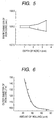
- FIG. 6 shows the result of another experiment which performed a rolling-bending process by using the rolling-bending apparatus according to the present invention.
- the ordinate represents the outer diameter mm of an iron core and the abscissa represents the amount of rolling ⁇ m.
- the amount of rolling varies by 1 ⁇ m
- the inner diameter of the iron core varies by 3 mm. From the fact, it will be understood that the retention of an equal amount of rolling is important for an improvement of the dimensional accuracy of the iron core.
- the contact area between the strip and each of the mill rolls 33, 34 intermittently changes. Accordingly, since the working stress caused by the mill rolls intermittently varies, it is difficult to precisely perform the position control. In general, it is extremely difficult to adjust an amount of rolling and stabilize a curvature.
- the amount of rolling is adjusted by the position control of the inlet guide 32 so that the post-process curvature of the strip 20 is adjusted thereby.
- the amount of rolling is adjusted.
- the amount of rolling is also adjusted by position control of the mill roll unit 35 so that the post-process curvature of the strip 20 is adjusted thereby.
- the amount of rolling is adjusted by changing the spacing between the two mill rolls 33 and 34. To change the spacing between the two mill rolls 33 and 34, one of the rolls 33 and 34, e.g.
- the restraint jig 36 may be moved in the direction indicated by the arrow B. Further, the curvature is adjusted by the position control of the restraint jig 36. By moving the restraint jig 36 in the direction indicated by the arrow C, i.e., in the widthwise direction of the strip 20, the post-process curvature of the strip 20 is finely adjusted.
- the thickness of the strip 20 is measured by the plate thickness measurement unit 31.
- the curvature of the strip 20 after the rolling-bending process is measured by the curvature measurement unit 37.
- the measured plate thickness and curvature are supplied to the arithmetic operation unit 38.
- the arithmetic operation unit 38 Based on the inputted plate thickness and curvature, the arithmetic operation unit 38 performs an arithmetic operation to obtain position control information to be supplied to the inlet guide 32, the mill roll unit 35, and the restraint jig 36.
- Experimental data may be used for the arithmetic operation for supplying the position control information.
- the positions of the inlet guide 32, the mill roll unit 35, and the restraint jig 36 are controlled based on the position control information supplied from the arithmetic operation unit 38.
- three types of position control which are the position control of the inlet guide 32, the position control of the mill roll unit 35, and the position control of the restraint jig 36, may be combined selectively and appropriately.
- the combination includes at least the position control of the inlet guide 32 or the position control of the restraint jig 36.
- the amount of rolling may be adjusted only by the position control of the inlet guide 32 or by the combination of the position control of the inlet guide 32 and the position control of the mill roll unit 35. If two or three types of position control are combined, a proper ratio of amount of these position controls is determined.
- the arithmetic operation unit 38 performs an arithmetic operation to determine an optimum value of the ratio among respective amounts of position control assigned to the inlet guide 32, the mill roll unit 35, and the restraint jig 36.
- a nip angle (double the taper angle ⁇ ) formed between the tapered portions 33A and 34A of the two mill rolls 33 and 34 is set to 0.5°. If moving the inlet guide 32 to the side of tips of the mill rolls 33 and 34 by 0.1 mm in parallel with these rolls, the strip 20 also moves to the side of tips of the mill rolls 33 and 34. This achieves a 0.8- ⁇ m reduction in the amount of rolling. Conversely, if moving the inlet guide 32 to the side of the basal portions of the mill rolls 33 and 34 in parallel with these rolls, the amount of rolling can be increased. It is sufficiently easy to perform position control of the inlet guide 32 on a per 0.1 mm basis. The position control of the inlet guide 32 allows fine adjustment of the amount of rolling.
- the position control of the mill roll unit 35 and the position control of the inlet guide 32 are combined.
- the majority of the adjustment of the amount of rolling is performed by the position control of the mill roll unit 35 and the fine adjustment of the amount of rolling is performed by the position control of the inlet guide 32.
- the arrangement allows high-precision adjustment of the amount of rolling.
- the amount of rolling is obtained by about 28 ⁇ m through the position control of the mill rolls 33 and 34.
- the inlet guide 32 is moved to the side of the tips of the mill rolls 33 and 34 by 0.25 mm, whereby the amount of rolling is increased by about 2 ⁇ m.
- the post-process curvature of the strip is varied by various factors including a variation in the mechanical property of the material thereof.
- the curvature measured by the curvature measurement unit 37 is further feedbacked.
- the arithmetic operation unit 38 determines a deviation between a measured value of the curvature and a design (target) value. Based on the deviation, the position control of the mill roll unit 35 and the position control of the inlet guide 32, which have been described above, are amended. For example, if the deviation is positive, i.e.
- an extremely high-precision iron core can be manufactured by feedbacking an output of the curvature measurement unit 37 to the mill roll unit 35 and to the inlet guide 32.
- the post-process curvature of the strip is further finely adjusted by using the restraint jig 36.
- the position control of the restraint jig 36 allows fine adjustment of the post-process curvature of the strip without changing the amount of rolling.
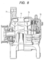
- FIG. 8 shows an example in which an iron core manufactured by the apparatus and method of the present invention is used in an ac power generator for an automobile.
- the iron core 10 is mounted and fixed between a front bracket 71 and a rear bracket 72.
- the iron core 10 of the present invention was excellent in dimensional accuracy, so that an ac power generator 73 for an automobile having high power generation efficiency was obtained.
- the present invention can use a steel plate or silicon steel plate having an extremely small thickness (less than 0.5 mm) that has conventionally been considered difficult to be used as a material for a spirally laminated iron core.
- An iron core composed of such an extremely thin plate achieves a higher-than-ever efficiency in the ac power generator 73 for an automobile.
- the iron core when an iron core for electric rotary machine is manufactured by forming the strip into a spirally laminated structure through a pressing-bending process, the iron core can be manufactured with high accuracy even if the strip thin plate has thickness variations.
Landscapes
- Engineering & Computer Science (AREA)
- Power Engineering (AREA)
- Manufacturing & Machinery (AREA)
- Manufacture Of Motors, Generators (AREA)
- Metal Rolling (AREA)
- Manufacturing Cores, Coils, And Magnets (AREA)
Applications Claiming Priority (2)
| Application Number | Priority Date | Filing Date | Title |
|---|---|---|---|
| JP2003326557A JP3894913B2 (ja) | 2003-09-18 | 2003-09-18 | 鉄心、及び、それを用いた車両用回転電機 |
| JP2003326557 | 2003-09-18 |
Publications (3)
| Publication Number | Publication Date |
|---|---|
| EP1517427A2 true EP1517427A2 (de) | 2005-03-23 |
| EP1517427A3 EP1517427A3 (de) | 2006-03-01 |
| EP1517427B1 EP1517427B1 (de) | 2015-04-15 |
Family
ID=34191352
Family Applications (1)
| Application Number | Title | Priority Date | Filing Date |
|---|---|---|---|
| EP04019827.7A Expired - Lifetime EP1517427B1 (de) | 2003-09-18 | 2004-08-20 | Blechpaket sowie Verfahren und Maschine zur Herstellung desselben |
Country Status (4)
| Country | Link |
|---|---|
| US (2) | US7315104B2 (de) |
| EP (1) | EP1517427B1 (de) |
| JP (1) | JP3894913B2 (de) |
| CN (2) | CN101295902B (de) |
Cited By (5)
| Publication number | Priority date | Publication date | Assignee | Title |
|---|---|---|---|---|
| DE102006016249A1 (de) * | 2006-03-31 | 2007-10-04 | Robert Bosch Gmbh | Stator für eine Elektromaschine und Verfahren zur Herstellung |
| DE102008001538A1 (de) * | 2008-05-05 | 2009-11-19 | Zf Friedrichshafen Ag | Elektrische Maschine mit einem Stator und/oder Rotor mit einem geschlitzten Blechpaket |
| WO2011096005A1 (en) * | 2010-02-05 | 2011-08-11 | Trancerie Emiliane S.P.A. | Process for making a stator or rotor lamination pack for a large electric rotating machine |
| EP2787610A1 (de) * | 2013-04-05 | 2014-10-08 | F. Boccadoro SA | Verfahren und Vorrichtung zur Herstellung von Statoren und Rotoren für axiale Motoren |
| EP3301795A1 (de) * | 2016-09-30 | 2018-04-04 | Wieland-Werke AG | Verfahren zur herstellung eines kurzschlussrings |
Families Citing this family (21)
| Publication number | Priority date | Publication date | Assignee | Title |
|---|---|---|---|---|
| JP2007068310A (ja) * | 2005-08-30 | 2007-03-15 | Aisin Seiki Co Ltd | 回転機の積層巻きコア |
| JP4176121B2 (ja) * | 2006-10-13 | 2008-11-05 | 株式会社三井ハイテック | 回転子積層鉄心およびその製造方法 |
| JP4483923B2 (ja) * | 2007-09-27 | 2010-06-16 | 株式会社デンソー | 回転電機のステータコアおよびその製造方法 |
| JP4518126B2 (ja) * | 2007-09-28 | 2010-08-04 | 株式会社デンソー | 回転電機のステータコアおよびその製造方法 |
| CN102361237B (zh) * | 2011-08-17 | 2014-11-26 | 岭澳核电有限公司 | 百万千瓦级先进压水堆核电站500kv变压器的检修方法 |
| US9490667B2 (en) * | 2013-07-23 | 2016-11-08 | General Electric Company | Apparatus and system for attaching integral spacers to laminations |
| US9614406B2 (en) | 2013-09-16 | 2017-04-04 | Nidec Motor Corporation | Wedge for stator having overmolded insulation |
| US9479022B2 (en) | 2013-09-16 | 2016-10-25 | Nidec Motor Corporation | Stator tooth wire retention wings |
| US9509181B2 (en) | 2013-12-10 | 2016-11-29 | Electric Torque Machines Inc. | Transverse flux stator geometry |
| JP5979128B2 (ja) * | 2013-12-24 | 2016-08-24 | Jfeスチール株式会社 | モータコアおよびその製造方法 |
| JP5979129B2 (ja) * | 2013-12-24 | 2016-08-24 | Jfeスチール株式会社 | モータコアの製造方法 |
| JP6102779B2 (ja) * | 2014-02-07 | 2017-03-29 | 株式会社デンソー | 回転電機の固定子鉄心 |
| US11255612B2 (en) | 2014-07-25 | 2022-02-22 | Enure, Inc. | Wound strip machine |
| DE112015003443T5 (de) | 2014-07-25 | 2017-04-06 | Prippell Technologies, Llc | Fluidgekühlte gewundene Streifenstruktur |
| CN104785930B (zh) * | 2015-04-14 | 2016-05-18 | 常州阿木奇声学科技有限公司 | 一种动铁单元方铁的制作治具及制作方法 |
| JP6504090B2 (ja) * | 2015-04-29 | 2019-04-24 | 株式会社デンソー | ステータコア成形装置およびステータコア成形方法 |
| JP6838466B2 (ja) * | 2017-04-03 | 2021-03-03 | 株式会社デンソー | 圧延曲げ加工方法及び圧延曲げ加工装置 |
| JP7077755B2 (ja) * | 2018-05-11 | 2022-05-31 | 株式会社デンソー | 圧延曲げ加工装置 |
| JP7342447B2 (ja) * | 2019-06-20 | 2023-09-12 | 株式会社デンソー | 回転電機及び回転電機の製造方法 |
| JP7371361B2 (ja) | 2019-06-20 | 2023-10-31 | 株式会社デンソー | 回転電機 |
| CN113451011B (zh) * | 2020-03-27 | 2026-03-17 | 株式会社博迈立铖 | Fe基软磁性非晶合金薄板及制法、层叠铁芯和旋转电机 |
Citations (3)
| Publication number | Priority date | Publication date | Assignee | Title |
|---|---|---|---|---|
| JPS62173955A (ja) | 1986-01-27 | 1987-07-30 | Sawafuji Electric Co Ltd | ステ−タコアの巻上げ装置 |
| JPH01164247A (ja) | 1987-12-21 | 1989-06-28 | Hitachi Ltd | 薄板曲げ加工による外周切欠き付きコアの製造装置 |
| US6023119A (en) | 1998-10-23 | 2000-02-08 | Mitsubishi Denki Kabushiki Kaisha | Alternator |
Family Cites Families (15)
| Publication number | Priority date | Publication date | Assignee | Title |
|---|---|---|---|---|
| US2845555A (en) * | 1955-09-12 | 1958-07-29 | Westinghouse Electric Corp | Motors |
| US3577851A (en) * | 1968-03-18 | 1971-05-11 | Lucas Industries Ltd | Method of making dynamoelectric machines |
| JPS5341321B1 (de) | 1971-07-30 | 1978-11-02 | ||
| US3886256A (en) * | 1971-07-30 | 1975-05-27 | Hitachi Ltd | Stator core for rotary electric machines and method of manufacturing the same |
| US4164133A (en) * | 1975-11-21 | 1979-08-14 | Holland Mechanics B.V. | Apparatus for forming circularly bent articles from a straight metal profiled strip |
| JPS5936503B2 (ja) * | 1976-12-28 | 1984-09-04 | 三菱電機株式会社 | 巻コアの形成方法とその形成装置 |
| US4445353A (en) * | 1981-09-17 | 1984-05-01 | Westinghouse Electric Corp. | Apparatus for manufacturing helical cores |
| US4914934A (en) * | 1984-10-12 | 1990-04-10 | General Electric Company | Method of forming an edgewise wound core |
| US4918962A (en) * | 1984-10-12 | 1990-04-24 | General Electric Company | Apparatus and method for forming edgewise wound cores |
| JPH0946938A (ja) * | 1995-07-26 | 1997-02-14 | Toshiba Corp | スピンドルモータ及びその製造方法、並びにスピンドルモータを備えた磁気ディスク装置 |
| DE19757451A1 (de) * | 1997-12-23 | 1999-06-24 | Asea Brown Boveri | Stator-Blechkörper für eine elektrische Maschine |
| JP3233135B2 (ja) | 1998-11-26 | 2001-11-26 | 株式会社デンソー | ステータコアのコア材の巻回装置 |
| US6308549B1 (en) * | 1998-11-26 | 2001-10-30 | Denso Corporation | Apparatus and method for forming spirally wound stator core or rotary electric machine |
| GB2349749B (en) | 1999-03-19 | 2001-03-07 | Mitsubishi Electric Corp | Stator core for car AC generator and process for producing stator core for car AC generator |
| EP1248347B1 (de) * | 2000-08-29 | 2008-01-23 | Mitsubishi Denki Kabushiki Kaisha | STATORBLECHKöRPER UND VERFAHREN ZUR HERSTELLUNG DESSELBEN |
-
2003
- 2003-09-18 JP JP2003326557A patent/JP3894913B2/ja not_active Expired - Fee Related
-
2004
- 2004-07-09 CN CN200810099975.9A patent/CN101295902B/zh not_active Expired - Fee Related
- 2004-07-09 CN CNB2004100634874A patent/CN100405702C/zh not_active Expired - Fee Related
- 2004-08-18 US US10/920,193 patent/US7315104B2/en not_active Expired - Lifetime
- 2004-08-20 EP EP04019827.7A patent/EP1517427B1/de not_active Expired - Lifetime
-
2007
- 2007-11-20 US US11/943,017 patent/US8302275B2/en not_active Expired - Fee Related
Patent Citations (3)
| Publication number | Priority date | Publication date | Assignee | Title |
|---|---|---|---|---|
| JPS62173955A (ja) | 1986-01-27 | 1987-07-30 | Sawafuji Electric Co Ltd | ステ−タコアの巻上げ装置 |
| JPH01164247A (ja) | 1987-12-21 | 1989-06-28 | Hitachi Ltd | 薄板曲げ加工による外周切欠き付きコアの製造装置 |
| US6023119A (en) | 1998-10-23 | 2000-02-08 | Mitsubishi Denki Kabushiki Kaisha | Alternator |
Cited By (6)
| Publication number | Priority date | Publication date | Assignee | Title |
|---|---|---|---|---|
| DE102006016249A1 (de) * | 2006-03-31 | 2007-10-04 | Robert Bosch Gmbh | Stator für eine Elektromaschine und Verfahren zur Herstellung |
| US8344580B2 (en) | 2006-03-31 | 2013-01-01 | Robert Bosch Gmbh | Stator for a polyphase electric machine and method for manufacturing same |
| DE102008001538A1 (de) * | 2008-05-05 | 2009-11-19 | Zf Friedrichshafen Ag | Elektrische Maschine mit einem Stator und/oder Rotor mit einem geschlitzten Blechpaket |
| WO2011096005A1 (en) * | 2010-02-05 | 2011-08-11 | Trancerie Emiliane S.P.A. | Process for making a stator or rotor lamination pack for a large electric rotating machine |
| EP2787610A1 (de) * | 2013-04-05 | 2014-10-08 | F. Boccadoro SA | Verfahren und Vorrichtung zur Herstellung von Statoren und Rotoren für axiale Motoren |
| EP3301795A1 (de) * | 2016-09-30 | 2018-04-04 | Wieland-Werke AG | Verfahren zur herstellung eines kurzschlussrings |
Also Published As
| Publication number | Publication date |
|---|---|
| US20080072415A1 (en) | 2008-03-27 |
| CN101295902A (zh) | 2008-10-29 |
| US20050061046A1 (en) | 2005-03-24 |
| JP3894913B2 (ja) | 2007-03-22 |
| EP1517427B1 (de) | 2015-04-15 |
| CN101295902B (zh) | 2011-07-13 |
| US8302275B2 (en) | 2012-11-06 |
| CN1599197A (zh) | 2005-03-23 |
| US7315104B2 (en) | 2008-01-01 |
| CN100405702C (zh) | 2008-07-23 |
| JP2005094951A (ja) | 2005-04-07 |
| EP1517427A3 (de) | 2006-03-01 |
Similar Documents
| Publication | Publication Date | Title |
|---|---|---|
| US8302275B2 (en) | Iron core and method of manufacturing the same and apparatus for manufacturing the same | |
| CA1254937A (en) | Lanced strip, core, method of forming such core, and apparatus | |
| CN108202087B (zh) | 变厚度金属板的制造方法、压制部件的制造方法及加工机 | |
| KR20000035197A (ko) | 벤딩 롤에 의한 파이프 성형장치, 성형방법 및 파이프 | |
| TWI439330B (zh) | The manufacturing method of profiled section | |
| US20090083965A1 (en) | Stator core for rotating electrical machine and method of manufacturing the same | |
| EP0076056B1 (de) | Apparat und Verfahren zur Herstellung spiralförmiger Blechkerne | |
| US10894277B2 (en) | Rolling bending method and rolling bending apparatus | |
| JP4398444B2 (ja) | 鉄心製造方法及び鉄心の製造装置 | |
| US20160276910A1 (en) | Method of manufacturing assembled conductor and electric motor | |
| US20240299996A1 (en) | Method for shaping wire material and wire material shaping device | |
| JP2012020305A (ja) | 薄型小断面積異形条の矯正方法及び矯正装置 | |
| JP4454441B2 (ja) | 異形断面帯材の断面矯正方法 | |
| JP2011147977A (ja) | 異形断面銅条材の製造方法 | |
| CN103688451B (zh) | 背铁及制造背铁的方法 | |
| JP2885102B2 (ja) | 圧延方法 | |
| JPH1147863A (ja) | 異形断面条の矯正方法 | |
| JPH1133628A (ja) | 金属板の矯正方法、金属製品の製造法および矯正装置 | |
| JPH06126366A (ja) | 異形横断面形状を有するリング材,板材,帯材の前方スピニング加工方法 | |
| JPH10166097A (ja) | 異形断面条の製造方法 | |
| JP2001105032A (ja) | ベンディングロールによるパイプ成形装置、成形方法及びパイプ | |
| JPH06262288A (ja) | 金型圧延処理装置 | |
| CN119447141A (zh) | 电极片的轧制装置及轧制方法 | |
| JPH11740A (ja) | 異形断面条の製造方法 | |
| JP2001300602A (ja) | 金属箔の製造方法 |
Legal Events
| Date | Code | Title | Description |
|---|---|---|---|
| PUAI | Public reference made under article 153(3) epc to a published international application that has entered the european phase |
Free format text: ORIGINAL CODE: 0009012 |
|
| AK | Designated contracting states |
Kind code of ref document: A2 Designated state(s): AT BE BG CH CY CZ DE DK EE ES FI FR GB GR HU IE IT LI LU MC NL PL PT RO SE SI SK TR |
|
| AX | Request for extension of the european patent |
Extension state: AL HR LT LV MK |
|
| PUAL | Search report despatched |
Free format text: ORIGINAL CODE: 0009013 |
|
| AK | Designated contracting states |
Kind code of ref document: A3 Designated state(s): AT BE BG CH CY CZ DE DK EE ES FI FR GB GR HU IE IT LI LU MC NL PL PT RO SE SI SK TR |
|
| AX | Request for extension of the european patent |
Extension state: AL HR LT LV MK |
|
| 17P | Request for examination filed |
Effective date: 20060315 |
|
| AKX | Designation fees paid |
Designated state(s): DE |
|
| 17Q | First examination report despatched |
Effective date: 20070522 |
|
| GRAP | Despatch of communication of intention to grant a patent |
Free format text: ORIGINAL CODE: EPIDOSNIGR1 |
|
| INTG | Intention to grant announced |
Effective date: 20141106 |
|
| GRAS | Grant fee paid |
Free format text: ORIGINAL CODE: EPIDOSNIGR3 |
|
| GRAA | (expected) grant |
Free format text: ORIGINAL CODE: 0009210 |
|
| AK | Designated contracting states |
Kind code of ref document: B1 Designated state(s): DE |
|
| RAP1 | Party data changed (applicant data changed or rights of an application transferred) |
Owner name: HITACHI CAR ENGINEERING CO., LTD. Owner name: HITACHI, LTD. |
|
| RIN1 | Information on inventor provided before grant (corrected) |
Inventor name: KIRIHARA, YUICHI C/O HITACHI CAR ENGINEERING CO.,L Inventor name: SASAKI, SUSUMU C/O HITACHI, LTD. Inventor name: UDEDA, TOSHIAKI C/O HITACHI, LTD. Inventor name: KOSHIZAKA, ATSUSHI C/O HITACHI CAR ENGINEERING CO. Inventor name: KAWAHARA, KEIJI C/O HITACHI, LTD. |
|
| REG | Reference to a national code |
Ref country code: DE Ref legal event code: R096 Ref document number: 602004046993 Country of ref document: DE Effective date: 20150528 |
|
| REG | Reference to a national code |
Ref country code: DE Ref legal event code: R097 Ref document number: 602004046993 Country of ref document: DE |
|
| PLBE | No opposition filed within time limit |
Free format text: ORIGINAL CODE: 0009261 |
|
| STAA | Information on the status of an ep patent application or granted ep patent |
Free format text: STATUS: NO OPPOSITION FILED WITHIN TIME LIMIT |
|
| 26N | No opposition filed |
Effective date: 20160118 |
|
| PGFP | Annual fee paid to national office [announced via postgrant information from national office to epo] |
Ref country code: DE Payment date: 20190806 Year of fee payment: 16 |
|
| REG | Reference to a national code |
Ref country code: DE Ref legal event code: R119 Ref document number: 602004046993 Country of ref document: DE |
|
| PG25 | Lapsed in a contracting state [announced via postgrant information from national office to epo] |
Ref country code: DE Free format text: LAPSE BECAUSE OF NON-PAYMENT OF DUE FEES Effective date: 20210302 |