EP1517293B1 - Verfahren zur elektrischen Ansteuerung von elektrochromen Elementen - Google Patents
Verfahren zur elektrischen Ansteuerung von elektrochromen Elementen Download PDFInfo
- Publication number
- EP1517293B1 EP1517293B1 EP04021400A EP04021400A EP1517293B1 EP 1517293 B1 EP1517293 B1 EP 1517293B1 EP 04021400 A EP04021400 A EP 04021400A EP 04021400 A EP04021400 A EP 04021400A EP 1517293 B1 EP1517293 B1 EP 1517293B1
- Authority
- EP
- European Patent Office
- Prior art keywords
- electrochromic
- voltage
- colouration
- circuit
- electrolyte
- Prior art date
- Legal status (The legal status is an assumption and is not a legal conclusion. Google has not performed a legal analysis and makes no representation as to the accuracy of the status listed.)
- Expired - Lifetime
Links
- 238000000034 method Methods 0.000 title claims abstract description 35
- 230000008569 process Effects 0.000 title claims description 7
- 239000003792 electrolyte Substances 0.000 claims description 33
- 238000005259 measurement Methods 0.000 claims description 12
- 230000006978 adaptation Effects 0.000 claims description 4
- 238000012505 colouration Methods 0.000 claims 14
- 238000004040 coloring Methods 0.000 abstract description 19
- 230000036961 partial effect Effects 0.000 abstract description 9
- 230000000977 initiatory effect Effects 0.000 abstract 1
- 238000004042 decolorization Methods 0.000 description 15
- 239000007784 solid electrolyte Substances 0.000 description 10
- 230000001419 dependent effect Effects 0.000 description 9
- 238000002845 discoloration Methods 0.000 description 8
- 230000003287 optical effect Effects 0.000 description 8
- DCYOBGZUOMKFPA-UHFFFAOYSA-N iron(2+);iron(3+);octadecacyanide Chemical compound [Fe+2].[Fe+2].[Fe+2].[Fe+3].[Fe+3].[Fe+3].[Fe+3].N#[C-].N#[C-].N#[C-].N#[C-].N#[C-].N#[C-].N#[C-].N#[C-].N#[C-].N#[C-].N#[C-].N#[C-].N#[C-].N#[C-].N#[C-].N#[C-].N#[C-].N#[C-] DCYOBGZUOMKFPA-UHFFFAOYSA-N 0.000 description 7
- QGLKJKCYBOYXKC-UHFFFAOYSA-N nonaoxidotritungsten Chemical compound O=[W]1(=O)O[W](=O)(=O)O[W](=O)(=O)O1 QGLKJKCYBOYXKC-UHFFFAOYSA-N 0.000 description 6
- 229960003351 prussian blue Drugs 0.000 description 6
- 239000013225 prussian blue Substances 0.000 description 6
- 229910001930 tungsten oxide Inorganic materials 0.000 description 6
- 238000010521 absorption reaction Methods 0.000 description 5
- 238000004043 dyeing Methods 0.000 description 5
- 239000011521 glass Substances 0.000 description 5
- 229920002037 poly(vinyl butyral) polymer Polymers 0.000 description 5
- 230000008859 change Effects 0.000 description 4
- 230000006378 damage Effects 0.000 description 4
- 239000011244 liquid electrolyte Substances 0.000 description 4
- 229920000642 polymer Polymers 0.000 description 4
- 239000000126 substance Substances 0.000 description 4
- 230000001133 acceleration Effects 0.000 description 3
- 238000004364 calculation method Methods 0.000 description 3
- 229920000767 polyaniline Polymers 0.000 description 3
- 230000002441 reversible effect Effects 0.000 description 3
- 238000010186 staining Methods 0.000 description 3
- YEJRWHAVMIAJKC-UHFFFAOYSA-N 4-Butyrolactone Chemical compound O=C1CCCO1 YEJRWHAVMIAJKC-UHFFFAOYSA-N 0.000 description 2
- 150000002500 ions Chemical class 0.000 description 2
- 230000007774 longterm Effects 0.000 description 2
- 239000000463 material Substances 0.000 description 2
- 230000003647 oxidation Effects 0.000 description 2
- 238000007254 oxidation reaction Methods 0.000 description 2
- GNRSAWUEBMWBQH-UHFFFAOYSA-N oxonickel Chemical compound [Ni]=O GNRSAWUEBMWBQH-UHFFFAOYSA-N 0.000 description 2
- 239000005518 polymer electrolyte Substances 0.000 description 2
- 230000009467 reduction Effects 0.000 description 2
- 238000003860 storage Methods 0.000 description 2
- 239000000758 substrate Substances 0.000 description 2
- XOLBLPGZBRYERU-UHFFFAOYSA-N tin dioxide Chemical compound O=[Sn]=O XOLBLPGZBRYERU-UHFFFAOYSA-N 0.000 description 2
- NLXLAEXVIDQMFP-UHFFFAOYSA-N Ammonia chloride Chemical compound [NH4+].[Cl-] NLXLAEXVIDQMFP-UHFFFAOYSA-N 0.000 description 1
- 229920001609 Poly(3,4-ethylenedioxythiophene) Polymers 0.000 description 1
- 238000002835 absorbance Methods 0.000 description 1
- 239000006096 absorbing agent Substances 0.000 description 1
- 239000000654 additive Substances 0.000 description 1
- 230000002411 adverse Effects 0.000 description 1
- 239000003963 antioxidant agent Substances 0.000 description 1
- 230000000712 assembly Effects 0.000 description 1
- 238000000429 assembly Methods 0.000 description 1
- 230000008901 benefit Effects 0.000 description 1
- 238000009835 boiling Methods 0.000 description 1
- 239000003638 chemical reducing agent Substances 0.000 description 1
- 150000001875 compounds Chemical class 0.000 description 1
- 239000002322 conducting polymer Substances 0.000 description 1
- 229920001940 conductive polymer Polymers 0.000 description 1
- 230000003247 decreasing effect Effects 0.000 description 1
- 239000002761 deinking Substances 0.000 description 1
- 238000007599 discharging Methods 0.000 description 1
- 230000000694 effects Effects 0.000 description 1
- 238000006056 electrooxidation reaction Methods 0.000 description 1
- 239000000945 filler Substances 0.000 description 1
- 230000006872 improvement Effects 0.000 description 1
- 229910021432 inorganic complex Inorganic materials 0.000 description 1
- 230000002427 irreversible effect Effects 0.000 description 1
- MHCFAGZWMAWTNR-UHFFFAOYSA-M lithium perchlorate Chemical compound [Li+].[O-]Cl(=O)(=O)=O MHCFAGZWMAWTNR-UHFFFAOYSA-M 0.000 description 1
- 229910001486 lithium perchlorate Inorganic materials 0.000 description 1
- 229910003002 lithium salt Inorganic materials 0.000 description 1
- 159000000002 lithium salts Chemical class 0.000 description 1
- 238000004519 manufacturing process Methods 0.000 description 1
- 229910044991 metal oxide Inorganic materials 0.000 description 1
- 150000004706 metal oxides Chemical class 0.000 description 1
- 238000012821 model calculation Methods 0.000 description 1
- 230000007935 neutral effect Effects 0.000 description 1
- 229910000480 nickel oxide Inorganic materials 0.000 description 1
- 229920000620 organic polymer Polymers 0.000 description 1
- 239000003960 organic solvent Substances 0.000 description 1
- 239000007800 oxidant agent Substances 0.000 description 1
- 230000001590 oxidative effect Effects 0.000 description 1
- 239000004014 plasticizer Substances 0.000 description 1
- 238000002360 preparation method Methods 0.000 description 1
- 230000002829 reductive effect Effects 0.000 description 1
- 150000003839 salts Chemical class 0.000 description 1
- 239000004984 smart glass Substances 0.000 description 1
- 239000007787 solid Substances 0.000 description 1
- 125000006850 spacer group Chemical group 0.000 description 1
- 238000002834 transmittance Methods 0.000 description 1
- 230000001960 triggered effect Effects 0.000 description 1
Images

Classifications
-
- G—PHYSICS
- G02—OPTICS
- G02F—OPTICAL DEVICES OR ARRANGEMENTS FOR THE CONTROL OF LIGHT BY MODIFICATION OF THE OPTICAL PROPERTIES OF THE MEDIA OF THE ELEMENTS INVOLVED THEREIN; NON-LINEAR OPTICS; FREQUENCY-CHANGING OF LIGHT; OPTICAL LOGIC ELEMENTS; OPTICAL ANALOGUE/DIGITAL CONVERTERS
- G02F1/00—Devices or arrangements for the control of the intensity, colour, phase, polarisation or direction of light arriving from an independent light source, e.g. switching, gating or modulating; Non-linear optics
- G02F1/01—Devices or arrangements for the control of the intensity, colour, phase, polarisation or direction of light arriving from an independent light source, e.g. switching, gating or modulating; Non-linear optics for the control of the intensity, phase, polarisation or colour
- G02F1/15—Devices or arrangements for the control of the intensity, colour, phase, polarisation or direction of light arriving from an independent light source, e.g. switching, gating or modulating; Non-linear optics for the control of the intensity, phase, polarisation or colour based on an electrochromic effect
- G02F1/163—Operation of electrochromic cells, e.g. electrodeposition cells; Circuit arrangements therefor
-
- G—PHYSICS
- G09—EDUCATION; CRYPTOGRAPHY; DISPLAY; ADVERTISING; SEALS
- G09G—ARRANGEMENTS OR CIRCUITS FOR CONTROL OF INDICATING DEVICES USING STATIC MEANS TO PRESENT VARIABLE INFORMATION
- G09G3/00—Control arrangements or circuits, of interest only in connection with visual indicators other than cathode-ray tubes
- G09G3/20—Control arrangements or circuits, of interest only in connection with visual indicators other than cathode-ray tubes for presentation of an assembly of a number of characters, e.g. a page, by composing the assembly by combination of individual elements arranged in a matrix no fixed position being assigned to or needed to be assigned to the individual characters or partial characters
- G09G3/34—Control arrangements or circuits, of interest only in connection with visual indicators other than cathode-ray tubes for presentation of an assembly of a number of characters, e.g. a page, by composing the assembly by combination of individual elements arranged in a matrix no fixed position being assigned to or needed to be assigned to the individual characters or partial characters by control of light from an independent source
- G09G3/38—Control arrangements or circuits, of interest only in connection with visual indicators other than cathode-ray tubes for presentation of an assembly of a number of characters, e.g. a page, by composing the assembly by combination of individual elements arranged in a matrix no fixed position being assigned to or needed to be assigned to the individual characters or partial characters by control of light from an independent source using electrochromic devices
-
- G—PHYSICS
- G09—EDUCATION; CRYPTOGRAPHY; DISPLAY; ADVERTISING; SEALS
- G09G—ARRANGEMENTS OR CIRCUITS FOR CONTROL OF INDICATING DEVICES USING STATIC MEANS TO PRESENT VARIABLE INFORMATION
- G09G2310/00—Command of the display device
- G09G2310/06—Details of flat display driving waveforms
- G09G2310/061—Details of flat display driving waveforms for resetting or blanking
-
- G—PHYSICS
- G09—EDUCATION; CRYPTOGRAPHY; DISPLAY; ADVERTISING; SEALS
- G09G—ARRANGEMENTS OR CIRCUITS FOR CONTROL OF INDICATING DEVICES USING STATIC MEANS TO PRESENT VARIABLE INFORMATION
- G09G2320/00—Control of display operating conditions
- G09G2320/02—Improving the quality of display appearance
Definitions
- the invention relates to a method for the electrical control of electrochromic arrangements, with the aid of which it is possible to control the translucency of these electrochromic elements continuously reproducible.
- the method By dynamically adapting the switching voltage to changing resistances in the system and to changing switching currents, the method also makes it possible to greatly accelerate the switching operation of electrochromic elements with high internal resistances due to large areas and / or comparatively low-conductivity electrolytes, without leading to stability losses.
- Electrochromism refers to the reversible color change of materials which is triggered by the flow of an electric current and / or the application of an electrical voltage.
- electrochromic substances from different classes of substances, eg. As metal oxides (example: tungsten oxide), inorganic complex compounds (example: Prussian blue) or electronically conductive organic polymers (Example: polyaniline). All have in common that they are colored differently in different oxidation states and that you can switch between these oxidation states reversibly by electrochemical oxidation or reduction. For most practical applications, preference is given to substances which can be switched at least between an uncolored and a colored state.
- Vehicle glazing with automatically changeable translucency (intelligent windows), large-area displays, switchable optical filters for cameras, microscopes, etc., or for auto-dimming rear view mirrors is used.
- the electrochromic materials are located between two electrodes of which at least one (eg, in displays or mirrors) or both (eg, in smart windows or switchable optical filters) are transparent.
- the electrochromic substances may be in the form of a film on the electrodes and / or be dissolved in the electrolyte.
- the invention relates to electrochromic arrangements with solid electrochromic layers, between which there is an electrolyte.
- This variant of electrochromic elements has a battery-like structure and accordingly also shows a battery-like electrical behavior, ie a current flow only during charging and discharging, the coloring and discoloration correspond.
- the current flow for changing the light transmittance of the electrochromic devices is usually caused in the prior art by applying a constant DC voltage, the polarity between coloration and discoloration is changed.
- the electrolyte is often a polymer electrolyte which is as stable as possible mechanically (such as, for example, in US Pat EP1227362 described) in order to obtain a loadable, for example in the building glazing practically usable electrochromic element.
- polymeric solid electrolytes usually consist of at least one suitable polymer, at least one plasticizer and at least one conductive salt, and optionally other additives, such as UV absorbers, fillers or antioxidants.
- the ionic conductivity of such polymeric solid electrolytes is several orders of magnitude worse than that of liquid electrolytes. The larger the polymer content in the solid electrolyte, the better its mechanical properties, but the worse is its ionic conductivity.
- the ionic conductivity of liquid electrolytes consisting of a high boiling point organic solvent such as ⁇ -butyrolactone and a lithium salt such as lithium perchlorate is around 10 -2 S / cm at + 25 ° C.
- the ionic conductivity of a polymeric solid electrolyte eg an ion-conductive PVB film, as in WO02 / 40578 on the other hand, it is only around 10 -5 S / cm at + 25 ° C. This greatly reduced ionic conductivity of polymeric solid electrolytes over liquid electrolytes results in a significant reduction in the switching speed of electrochromic devices when operated with the electrochromic element electrical driving techniques known in the art.
- coloring and decolorization are carried out by applying a constant DC voltage, which is usually between 0.5 and 3 V and whose polarity is changed between dyeing and decolorization processes.
- a constant DC voltage which is usually between 0.5 and 3 V and whose polarity is changed between dyeing and decolorization processes.
- Various elements have been proposed for infinitely variable adjustment of elements. So is in EP78464 described an optical control circuit for electrochromic elements in which the absorption of the electrochromic element is continuously optically measured, the signal compared with a predetermined value and then electrical charges to the element or to be discharged from the element until the measured optical absorption corresponds to the desired value ,
- such a method is expensive, especially since a light source and a detector must be mounted on the opposite sides of the electrochromic element for measurement.
- DE3142909 For example, a continuous charge control for electrochromic layers is described in which the continuous adjustment of the degree of absorption via the counting of the electrical charges that are supplied to or removed from the electrochromic layer. This method represents a significant improvement over the optical measurement of the absorbance, as the charge count can be integrated directly into the electronic circuit.
- DE3142909 also stated that for the Entfärbevor Cyprus smaller amounts of charge are removed than were supplied during dyeing.
- a permanently reversible circuit is only possible if the charge quantities for coloring and decolorization are as equal as possible.
- WO02 / 17008 a method and a device for charging and temperature-controlled circuit of electrochromic elements are described.
- the temperature of the electrochromic element is measured by a temperature sensor, for switching then a temperature-dependent voltage is applied and also the switching operation is controlled by the amount of electrical charge flowing.
- EP445720 For example, a method and an arrangement for applying an electrical operating voltage to an electro-optical layer system are described, with the aim of faster switching of electrochromic elements.
- This accelerated circuit is achieved in that at the beginning of the switching process, a higher voltage than the actually maximum permissible internal potential difference between the two transparent conductive layers is applied to compensate for the voltage drop in these conductive layers.
- the otherwise usual voltage is applied again.
- the course of the voltage can be time-controlled and adapted to a predetermined voltage-time curve or the measurement of an internal potential difference takes place directly between opposite points of the electrochromic layers (a previously defined limit value may not be exceeded here).
- a similar technique is in the US patent US5124833 described. Although these methods can compensate for the voltage drop in the transparent conductive layers, not the often considerable voltage drop in the electrolyte.
- a linear temperature dependence is therefore only allowed as an approximation for small temperature intervals. When used over a wide temperature range, this leads to irreversible destruction of the electrochromic elements during long-term operation.
- the necessary experimental determination of the constants A and B is also laborious. For a temperature-adapted control voltage, a measurement of the element temperature must take place. This can after DE19839748 by means of a temperature sensor which is arranged in the region of the spacer of the electrochromic insulating glass happen. However, this means an extra effort in the production and increases the cost of electrochromic glazing.
- electrochromic elements can be switched steplessly via an optical control of the degree of absorption or via the control of the electric charges that have flowed.
- each optical intermediate state is adjustable.
- An acceleration of the circuit of larger electrochromic elements by increasing the drive voltage as compensation for the voltage drop of the transparent conductive layers is also known.
- An object of the invention is therefore primarily to provide a novel method for the electrical control of electrochromic elements, in which not only the voltage drops in the transparent conductive layers but also the voltage drop in the solid electrolyte between the electrochromic layers by a dynamic change of the driving voltage during the circuit can be compensated.
- Another object of the present invention is to provide a simple method of controlling the depth of staining of electrochromic elements.
- the continuous circuit via the control of the open circuit voltage.
- the switching process is interrupted in short successive intervals for short tent and here measured the open circuit voltage, which is compared with the resulting for the desired color depth open circuit voltage. If this is reached, the dyeing or Entfärbevorgang is interrupted. In this procedure can be dispensed with the control of the electric charges flowed.
- the resistance of the transparent conductive layers R TCO remains largely unchanged under the operating conditions of an electrochromic element, the resistance of the electrolyte R electrolyte may change by several orders of magnitude due to temperature changes, which in practical applications may be between about -40 and + 90 ° C ,
- the electrolyte resistance determined in this way is used to dynamically adapt the switching voltage according to Equations 6 and 7.
- a measurement of the temperature of the electrochromic element is no longer necessary.
- An advantage of this method is that no temperature sensor has to be integrated into the glazing area.
- the partial stresses for the coloring U 1, coloring and for the decolorization U 1, decolorization are chosen so that the electrochromic elements are not damaged even with a long concern of this tension.
- this requirement is met if the voltage for the coloration U 1, coloration amount less than or equal to the open circuit voltage of fully colored and the voltage for the discoloration U 1, decolorization amount less than or equal to the open circuit voltage of the fully decolorbed electrochromic element. Even voltages that are slightly above these no-load voltages are permissible.
- the no-load voltages of the fully colored or fully decolorized state of the electrochromic element may not be exceeded by more than a factor of 1.5.
- the magnitude of the no-load voltages of the fully colored and decolorized state are typical of the actually selected electrochromic layer combinations and the electrolytes used and can be temperature-dependent.
- the electrical resistance R of the electrochromic element is composed, as indicated in equation 2 , of 4 partial resistances, the resistance of the transparent conductive layer R TCO , which depends on the area and the sheet resistivity of the TCO layer, the resistances of the two switchable layers (EC 1 and EC 2 ) R EC1 and R EC2 and the high temperature-dependent resistance of the electrolyte R electrolyte .
- R R 1 ⁇ CO + R EC ⁇ 1 + R EC ⁇ 2 + R Elekrolyt
- the resistance of the transparent conductive layer R TCO in an electrochromic element of predetermined geometry remains largely uninfluenced by the practically occurring disk temperatures (for example between -40 and + 90 ° C.) and the switching state of the element. It can from the product of sheet resistance R SQ of the TCO layer with the contact distance I 1 [cm] divided by the width I 2 [cm] of the electrochromic element are calculated (Equation 3 ).
- R TCO R sq ⁇ I 1 / I 2
- the dynamic partial stresses for the coloring U 2, coloring and for the decolorization U 2, decolorization to the partial resistances R electrolyte and R TCO and to the current flowing in the circuit i are continuously after U 2 .
- coloring i ⁇ a ⁇ R electrolyte + b ⁇ R TCO respectively.
- the constants a to d are between 0 and 1 and indicate to what degree the corresponding resistance of the transparent conductive layer R TCO or of the electrolyte R electrolyte enter into the equation. If the constants a and c are equal to 1, the calculation of the dynamic partial voltage U 2 according to Equations 4 and 5 takes into account the full voltage drop across the electrolyte. If a and c are greater than 1, there is a risk of applying too high effective voltages to the electrochromic element, which could lead to damage and ultimately to the destruction of the electrochromic element.
- the permissible value for b and d in continuous operation is a maximum of 0.666, since damage to the electrochromic elements does not occur here even at high switching cycle numbers.
- the total voltage for coloring or discoloring an electrochromic element is therefore calculated by the method according to the invention for the electrical control of electrochromic elements, as indicated in Equations 6 and 7 :
- U switching . coloring U 1 . coloring + i ⁇ a ⁇ R electrolyte + b ⁇ R TCO respectively.
- U switching . discoloration U 1 . discoloration + i ⁇ c ⁇ R electrolyte + b ⁇ R TCO
- the partial voltage U 1, coloring or when decolorizing U 1, discoloration is applied to the electrochromic element.
- the then flowing current i is measured and the new voltage to be applied U switching, coloring or U switching, discoloration calculated according to equations 6 or 7 above and applied to the element.
- measurement of the current, calculation and application of the new switching voltage are repeated until the desired color depth is reached.
- the time intervals for the adaptation of the drive voltage are preferably between 10 milliseconds and 5 seconds.
- leakage currents and / or traces of oxidizing and / or reducing agents present in the polymer electrolyte can influence the state of charge independently of the controlled charge quantities.
- deepening or deep discharge of the element therefore takes place in certain embodiments at certain larger time intervals, which may preferably be between 1 hour and 3 months.
- a deinking voltage is applied for a period of time which may be between 5 minutes and 2 hours, which is 0.3 to 2.4 V in magnitude over the open circuit voltage of the fully decolorized electrochromic element. This can, in order not to impair the functionality of the elements during the day, for example, occur at night in the above-mentioned intervals, when the switching function of the electrochromic element is not used anyway.
- An electrochromic element of the structure is an electrochromic element of the structure:
- the basic decolorization was carried out by applying a DC voltage of 2.4 V for 2 hours, with the Prussian blue as the negative pole and the tungsten oxide as the positive pole.
- the open-circuit voltage of the decolorized state was determined. It was -720 mV.
- the electrochromic element was dyed by applying a voltage of 1.4 V (tungsten oxide: negative pole, Prussian blue: positive pole). After a charge amount of 15 mC / cm 2 had flowed, the dyeing operation was terminated and the open circuit voltage of the colored state was determined. It was +1100 mV.
- the relationship between injected charge amount and open circuit voltage was determined.
- the fully colored electrochromic element was decolorized by applying a direct voltage of 1.4 V for three minutes (tungsten oxide: positive pole, Prussian blue: negative pole). Thereafter, the element was stained again step by step by applying 1.4 V of reverse polarity and, in the meantime, the no-load voltage was measured and the flows discharged per area calculated.
- the relationship thus determined between injected charges and no-load voltage is shown in FIG. It can be seen that this relationship can be used to evaluate and control the amount of injected charges and thus the depth of coloration of an electrochromic element.
- Curve 1 shows the current density-time curve for staining and decolorization within the illustrated time of 480 seconds.
- 8 coloring and decoloring cycles are carried out (curve 2).
- the faster circuit in the method according to the invention can also be recognized by the higher current density and the charge connected per time.
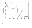
- FIG. 3 shows the time profile of the switching voltage for a circuit according to the prior art with constant voltage (here ⁇ 1.4 V, curve 2) and for the circuit according to the invention with continuous adaptation of the switching voltage to the resistor and the flowing current (curve 1).
- constant voltage here ⁇ 1.4 V, curve 2
- curve 1 the circuit according to the invention with continuous adaptation of the switching voltage to the resistor and the flowing current (curve 1).
- high switching voltages of approximately 12 V are achieved, but they do not adversely affect the electrochromic element.
- the applied voltages are even smaller in the method according to the invention than in the case of the constant-voltage circuit, so that the electrochromic element is switched overall more gently.
Landscapes
- Physics & Mathematics (AREA)
- Engineering & Computer Science (AREA)
- General Physics & Mathematics (AREA)
- Nonlinear Science (AREA)
- Computer Hardware Design (AREA)
- Theoretical Computer Science (AREA)
- Optics & Photonics (AREA)
- Control Of Indicators Other Than Cathode Ray Tubes (AREA)
- Electrochromic Elements, Electrophoresis, Or Variable Reflection Or Absorption Elements (AREA)
Description
- Die Erfindung betrifft ein Verfahren zur elektrischen Ansteuerung von elektrochromen Anordnungen, mit dessen Hilfe es möglich ist die Lichtdurchlässigkeit dieser elektrochromen Elemente stufenlos reproduzierbar zu steuern. Das Verfahren ermöglicht durch die dynamische Anpassung der Schaltspannung an sich ändernde Widerstände im System und an sich ändernde Schaltströme auch eine starke Beschleunigung des Schaltvorganges von elektrochromen Elementen mit hohen inneren Widerständen aufgrund grosser Flächen und/oder vergleichsweise niedrig leitfähiger Elektrolyte, ohne zu Stabilitätseinbußen zu führen.
- Mit Elektrochromie wird die reversible Farbänderung von Materialien bezeichnet, welche durch das Fließen eines elektrischen Stromes und/oder das Anlegen einer elektrischen Spannung ausgelöst wird. Es gibt eine Vielzahl elektrochromer Substanzen aus verschiedenen Substanzklassen, z. B. Metalloxide (Beispiel: Wolframoxid), anorganische Komplexverbindungen (Beispiel: Preußisch Blau) oder elektronisch leitfähige organische Polymere (Beispiel: Polyanilin). Allen ist gemeinsam, dass sie in unterschiedlichen Oxidationszuständen verschieden gefärbt sind und dass man zwischen diesen Oxidationszuständen reversibel durch elektrochemische Oxidation bzw. Reduktion schalten kann. Für die meisten in Frage kommenden praktischen Anwendungen bevorzugt man Substanzen, die mindestens zwischen einem ungefärbten und einem gefärbten Zustand schaltbar sind.
- Zur praktischen Nutzung des Effektes der Elektrochromie werden elektrochrome Anordnungen oder Elemente verwendet, in denen die elektrisch gesteuerte Modulation des einfallenden Lichtes für verschiedene Anwendungszwecke, wie z.B. für Gebäude- und
- Fahrzeugverglasungen mit automatisch veränderbarer Lichtdurchlässigkeit (intelligente Fenster), großflächige Displays, schaltbare optische Filter für Kameras, Mikroskope usw. oder auch für automatisch abblendbare Autorückspiegel eingesetzt wird.
- In elektrochromen Anordnungen befinden sich die elektrochromen Materialien zwischen zwei Elektroden von denen mindestens eine (z.B. bei Displays oder Spiegeln) oder beide (z.B. bei intelligenten Fenstern oder schaltbaren optischen Filtern) transparent sind. Die elektrochromen Substanzen können sich als Film auf den Elektroden befinden und/oder im Elektrolyten gelöst vorliegen. Die Erfindung bezieht sich auf elektrochrome Anordnungen mit festen elektrochromen Schichten, zwischen denen sich ein Elektrolyt befindet. Diese Variante elektrochromer Elemente hat einen batterieähnlichen Aufbau und zeigt dementsprechend auch ein batterieähnliches elektrisches Verhalten, d.h. ein Stromfluss muss nur während der Lade- und Entladevorgänge, die Färbung und Entfärbung entsprechen, erfolgen. Der Stromfluss zur Änderung der Lichtdurchlässigkeit der elektrochromen Anordnungen wird nach dem Stand der Technik in der Regel durch Anlegen einer zeitlich konstanten Gleichspannung hervorgerufen, wobei die Polarität zwischen Färbung und Entfärbung gewechselt wird.
- Der Aufbau eines solchen elektrochromen Elementes kann wie folgt schematisch dargestellt werden:
- Substrat 1 / TCO / EC1 / Elektrolyt / EC2 / TCO / Substrat 2
- Bei elektrochromen Elementen wird als Elektrolyt oft ein möglichst mechanisch stabiler polymerer Festelektrolyt (wie z.B. in
EP1227362 beschrieben) vorgeschlagen, um ein belastungsfähiges, z.B. in der Gebäudeverglasung praktisch einsetzbares elektrochromes Element zu erhalten. Solche polymeren Festelektrolyte bestehen in der Regel aus mindestens einem geeigneten Polymer, mindestens einem Weichmacher und mindestens einem Leitsalz so wie gegebenenfalls weiteren Zusätzen, wie z.B. UV-Absorbern, Füllstoffen oder Antioxidantien. Die lonenleitfähigkeit solcher polymerer Festelektrolyte ist um mehrere Größenordnungen schlechter als die von flüssigen Elektrolyten. Je größer der Polymeranteil im Festelektrolyten, desto besser sind seine mechanischen Eigenschaften umso schlechter ist aber seine lonenleitfähigkeit. Typischerweise beträgt die lonenleitfähigkeit von flüssigen Elektrolyten bestehend aus einem hochsiedenden organischen Lösungsmittel wie zum Beispiel γ-Butyrolacton und einem Lithiumsalz wie zum Beispiel Lithiumperchlorat um 10-2 S/cm bei +25°C. Die lonenleitfähigkeit eines polymeren Festelektrolyten, z.B. einer ionenleitenden PVB-Folie, wie inWO02/40578 - Es sind nach dem Stand der Technik verschiedene Varianten von Verfahren zur elektrischen Ansteuerung von elektrochromen Elementen bekannt.
- Im einfachsten Fall erfolgen Färbung und Entfärbung durch Anlegen einer zeitlich konstanten Gleichspannung, die meist zwischen 0,5 und 3 V liegt und deren Polarität zwischen Färbe-und Entfärbevorgängen gewechselt wird. Um den Absorptionsgrad der elektrochromen Elemente stufenlos einzustellen zu können, wurden verschiedene Verfahren vorgeschlagen. So ist in
EP78464 - In
DE3142909 ist eine kontinuierliche Ladungssteuerung für elektrochrome Schichten beschrieben, bei der die stufenlose Einstellung des Absorptionsgrades über das Zählen der elektrischen Ladungen, die der elektrochromen Schicht zugeführt oder entnommen werden, erfolgt. Dieses Verfahren stellt eine wesentliche Verbesserung gegenüber der optischen Messung des Absorptionsgrades dar, da die Ladungszählung direkt in die elektronische Schaltung integriert werden kann. Allerdings wird inDE3142909 auch ausgesagt, dass für die Entfärbevorgänge kleinere Ladungsmengen entnommen werden, als beim Färben zugeführt wurden. Eine dauerhaft reversible Schaltung ist jedoch nur möglich wenn die Ladungsmengen für Färbung und Entfärbung möglichst gleich groß sind. - In
WO02/17008 - In
EP445720 US5124833 beschrieben. Mit diesen Methoden kann zwar der Spannungsabfall in den transparenten Leitschichten, nicht aber der oft beträchtliche Spannungsabfall im Elektrolyten kompensiert werden. - In
DE19706918 ist ebenfalls ein Verfahren zum Betreiben eines elektrochromen Elementes beschrieben. Dabei wird in einer Anlaufphase des Umfärbevorganges die Spannung stetig bis maximal zu einem temperaturabhängigen Endwert erhöht bzw. erniedrigt, wobei die Spannung abhängig vom Strom geführt wird. Die maximal zulässige Schaltspannung Umax hängt dabei linear von der Element temperatur nach Umax = A - B·T ab. A und B sind für das verwendete System charakteristische Konstanten und experimentell zu ermitteln. Die Temperaturabhängigkeit der Schaltspannung wird durch die starke Temperaturabhängigkeit der Leitfähigkeit des polymeren Festelektrolyten hervorgerufen. Diese ist jedoch real nicht linear von der Temperatur abhängig, sondern gehorcht einem komplizierteren Zusammenhang, der sogenannten Vogel-Tamann-Fulcher-Beziehung. Eine lineare Temperaturabhängigkeit ist deshalb nur als Näherung für kleine Temperaturintervalle zulässig. Wenn sie über größere Temperaturbereiche angewandt wird, führt das im Langzeitbetrieb zur irreversiblen Zerstörung der elektrochromen Elemente. Aufwendig ist auch die notwendige experimentelle Ermittlung der Konstanten A und B. Für eine temperaturangepasste Ansteuerspannung muss eine Messung der Elementtemperatur erfolgen. Diese kann nachDE19839748 mittels eines Temperaturfühlers, welcher im Bereich des Abstandshalters des elektrochromen Isolierglases angeordnet ist, geschehen. Das bedeutet aber einen zusätzlichen Aufwand bei der Herstellung und erhöht die Kosten einer elektrochromen Verglasung. - Der Stand der Technik lässt sich also wie folgt zusammenfassen: Es ist bekannt, dass elektrochrome Elemente stufenlos über eine optische Kontrolle des Absorptionsgrades oder über die Kontrolle der geflossenen elektrischen Ladungen geschaltet werden können. Prinzipiell ist damit jeder optische Zwischenzustand einstellbar. Des weiteren ist bekannt, eine temperaturabhängige zeitlich unveränderliche Ansteuerspannung zu verwenden, wobei meist eine linear von der Temperatur abhängige Spannung verwendet wird und eine Messung der Temperatur notwendig ist. Eine Beschleunigung der Schaltung größerer elektrochromer Elemente durch Erhöhung der Ansteuerspannung als Kompensation des Spannungsabfalls der transparenten leitfähigen Schichten ist ebenfalls bekannt.
- Nachteilig bei diesem beschriebenen Stand der Technik ist vor allem, dass damit die geringe Schaltgeschwindigkeit elektrochromer Elemente bei Verwendung mechanisch sehr stabiler, aber mit vergleichsweise niedriger lonenleitfähigkeit ausgestatteter Polymerfestelektrolyte nicht erhöht werden kann.
- Eine Aufgabe der Erfindung besteht deshalb vor allem darin, ein neuartiges Verfahren zur elektrischen Ansteuerung von elektrochromen Elementen anzugeben, bei dem durch eine dynamische Änderung der Ansteuerspannung während der Schaltung nicht nur die Spannungsabfälle in den transparenten Leitschichten sondern auch der Spannungsabfall im Festelektrolyten zwischen den elektrochromen Schichten kompensiert werden kann.
- Dadurch können elektrochrome Elemente mit polymeren Festelektrolyten prinzipiell genauso schnell geschaltet werden, wie elektrochrome Elemente mit flüssigen Elektrolyten ohne die Dauerstabilität des Systems zu gefährden. Ziel der vorliegenden Erfindung ist es weiterhin, eine einfache Methoden der Kontrolle der Färbungstiefe elektrochromer Elemente zu liefern.
- Überraschenderweise wurde gefunden, dass eine bisher nicht erreichte Beschleunigung der Schaltgeschwlndigkelt elektrochromer Elemente mit vergleichsweise schlecht leitenden Polymerfestelektrolyen und/oder mit relativ hohen Widerständen der TCO-Schichten aufgrund der Größe der elektrochromen Elemente erreicht werden kann, indem die Gleichspannung zur Färbung USchalt, Färbung und die Gleichspannung zur Entfärbung USchalt,Entferbung des Elementes jeweils aus 2 Teilspannungen U1 und U2 zusammengesetzt werden, wobei die Tellspannung U2 dynamisch an den bei der Schaltung fließenden Strom I und an den stark temperaturabhängigen elektrischen Widerstand des elektrochromen Elementes R angepasst wird.
- Wichtig für eine dauerhaft reproduzierbare Schaltung elektrochromer Elemente ist auch die Kontrolle Ihres Färbungsgrades, die nach dem Stand der Technik über eine optische Messung bzw. über die Kontrolle und Speicherung der beim Schalten geflossenen Landungen erfolgt. Überraschenderweise wurde gefunden, dass die Färbungstiefe bzw. die Menge der injizierten Ladungen der Leerlaufspannung ULeerlauf des elektrochromen Elementes proportional sind. Demzufolge erfolgt erfindungsgemäß die stufenlose Schaltung über die Kontrolle der Leerlaufspannung. Dazu wird der Schaltvorgang in kurzzeitig aufeinanderfolgenden Intervallen für kurze Zelt unterbrochen und hier die Leerlaufspannung gemessen, die mit der für die gewünschte Farbtiefe sich ergebenden Leerlaufspannung verglichen wird. Ist diese erreicht, wird der Färbe- oder Entfärbevorgang unterbrochen. Bei dieser Vorgehensweise kann auf die Kontrolle der geflossenen elektrischen Ladungen verzichtet werden.
- Während der Widerstand der transparenten Leitschichten RTCO unter den Betriebsbedingungen eines elektrochromen Elementes weitgehend unverändert bleibt, kann sich der Widerstand des Elektrolyten RElektrolyt aufgrund von Temperaturänderungen, die bei praktischen Anwendungen zwischen etwa -40 und +90°C liegen können, um mehrere Größenordnungen ändern.
- In der erfindungsgemässen Ausführung des Verfahrens zur elektrischen Ansteuerung von elektrochromen Elementen wird deshalb der stark temperaturabhängige Widerstand RElektrolyt des Ionenleitenden Elektrolyten in bestimmten Zeitintervallen während des Schaltvorganges gemessen. Es wurde nämlich überraschenderweise festgestellt, dass die Ermittlung des Widerstandes R des elektrochromen Elementes sehr einfach durch Messung der Leerlaufspannung des elektrochromen Elementes ULeerlauf, Anlegen einer Schaltspannung USchalt und Messung des dabei fließenden Stromes i sowie anschließender Berechnung nach Gleichung 1 erfolgen kann:

- Zur Messung der Leerlaufspannung muss der Schaltvorgang kurzzeitig unterbrochen werden. Diese neue, erfindungsgemäße Methode zur Bestimmung des aktuellen Gesamtwiderstandes der elektrochromen Elemente kann sowohl bei der Färbung als auch bei der Entfärbung durchgeführt werden. Aus diesem ermittelten Gesamtwiderstand und dem nach Gleichung 3 errechneten TCO-Wlderstand lässt sich der Widerstand des Elektrolyten nach Gleichung 2 unter Vernachlässigung der Widerstände der beiden schaltbaren Schichten (EC1 und EC2) berechnen.
- Der so bestimmte Elektrolytwiderstand wird zur dynamischen Anpassung der Schaltspannung gemäß Gleichung 6 und 7 verwendet. Bei dieser Verfahrensweise ist eine Messung der Temperatur des elektrochromen Elementes nicht mehr nötig. Ein Vorteil dieses Verfahrens ist es, dass kein Temperatursensor in den Verglasungsbereich integriert werden muss.
- Erfindungsgemäß werden die Teilspannungen für die Färbung U1,Färbung und für die Entfärbung U1,Entfärbung so gewählt, dass die elektrochromen Elemente auch bei einem langen Anliegen dieser Spannung nicht geschädigt werden. In der Regel ist diese Forderung erfüllt, wenn die Spannung für die Färbung U1,Farbung betragsmäßig kleiner oder gleich der Leerlaufspannung des voll gefärbten und die Spannung für die Entfärbung U1,Entfärbung betragsmäßig kleiner oder gleich der Leerlaufspannung des voll entfärbten elektrochromen Elementes sind. Auch Spannungen, die wenig oberhalb dieser Leerlaufspannungen liegen, sind zulässig. Die Leerlaufspannungen des voll gefärbten bzw. voll entfärbten Zustandes des elektrochromen Elementes dürfen aber um nicht mehr als den Faktor 1,5 überschritten werden. Die Grösse der Leerlaufspannungen des voll gefärbten und entfärbten Zustandes sind typisch für die konkret gewählten elektrochromen Schichtkombinationen und die verwendeten Elektrolyte und können temperaturabhängig sein.
- Der elektrische Widerstand R des elektrochromen Elementes setzt sich, wie in Gleichung 2 angegeben, aus 4 Teilwiderständen zusammen, dem von der Fläche und dem spezifischen Flächenwiderstand der TCO-Schicht abhängigen Widerstand der transparenten Leitschicht RTCO, den Widerständen der beiden schaltbaren Schichten (EC1 und EC2) REC1 und REC2 und dem stark temperaturabhängigen Widerstand des Elektrolyten RElektrolyt.

- Der Widerstand der transparenten Leitschicht RTCO bleibt in einem elektrochromen Element vorgegebener Geometrie weitgehend unbeeinflusst von den praktisch auftretenden Scheibentemperaturen (etwa zwischen - 40 und + 90°C) und vom Schaltzustand des Elementes. Er kann aus dem Produkt des Flächenwiderstandes RSQ der TCO-Schicht mit dem Kontaktabstand I1 [cm] geteilt durch die Breite I2 [cm] des elektrochromen Elementes berechnet werden (Gleichung 3 ).

- Überraschenderweise wurde gefunden, dass es für das erfindungsgemäße 3 Verfahren zur elektrischen Ansteuerung elektrochromer Elemente ausreichend ist, die Widerstände der transparenten Leitschicht RTCO und des Elektrolyten RElektrolyt auszuwerten, da die Widerstände der elektrochromen Schichten REC1 und REC2 in praxisrelevanten elektrochromen Anordnungen (Gebäudeverglasungen, Fahrzeugverglasungen, Autorückspiegel, grossflächige Informationsanzeigen) mit relativ niedrig leitfähigen Elektrolyten und/oder grossen zu schaltenden Flächen klein gegenüber RTCO und RElektrolyt sind.
- Erfindungsgemäß werden daher die dynamischen Teilspannungen für die Färbung U2,Färbung und für die Entfärbung U2,Entfärbung an die Teilwiderstände RElektrolyt und RTCO und an den bei der Schaltung fliessenden Strom i laufend nach


- Die Konstanten a bis d liegen zwischen 0 und 1 und geben an, bis zu welchem Grad der entsprechende Widerstand der transparenten Leitschicht RTCO bzw. des Elektrolyten RElektrolyt in die Gleichung eingehen. Wenn die Konstanten a und c gleich 1 betragen, wird mit der Berechnung der dynamischen Teilspannung U2 nach Gleichung 4 und 5 der volle Spannungsabfall über den Elektrolyten berücksichtigt. Sind a und c grösser 1 besteht die Gefahr des Anlegens zu hoher wirksamer Spannungen an das elektrochrome Element, was zu Schädigungen und letztlich zur Zerstörung des elektrochromen Elementes führen könnte.
- Es hat sich weiterhin gezeigt, dass der Widerstand der TCO-Schicht nicht vollständig kompensiert werden kann (das würde bedeuten: b bzw. d = 1), wenn die wirksamen Spannungen im Randbereich des elektrochromen Elementes nicht zu hoch sein sollen. Nach eigenen Modellberechnungen beträgt der im Dauerbetrieb zulässige Wert für b und d maximal 0,666, da es hier auch bei hohen Schaltzyklenzahlen nicht zu einer Schädigung der elektrochromen Elemente kommt.
- Die Gesamtspannung zur Färbung bzw. Entfärbung eines elektrochromen Elementes berechnet sich also nach dem erfindungsgemäßen Verfahren zur elektrischen Ansteuerung von elektrochromen Elementen wie in Gleichung 6 und 7 angegeben:


- Bei Beginn eines solchen erfindungsgemäßen Schaltvorganges wird an das elektrochrome Element die Teilspannung U1, Färbung bzw. beim Entfärben U1, Entfärbung angelegt. Der dann fliessende Strom i wird gemessen und die neue anzulegende Spannung USchalt,Färbung bzw. USchalt,Entfärbung nach den oben angegebenen Gleichungen 6 bzw. 7 berechnet und an das Element angelegt. Dann erfolgt wiederum Messung des Stroms, Berechnung und Anlegen der neuen Schaltspannung. Diese Vorgänge werden solange wiederholt, bis die gewünschte Färbungstiefe erreicht ist. Erfindungsgemäß betragen die Zeitintervalle für die Anpassung der Ansteuerspannung vorzugsweise zwischen 10 Millisekunden und 5 Sekunden.
- Über eine längere Zeitdauer des Betriebes eines elektrochromen Elementes kann es durch Kriechströme und/oder im Polymerelektrolyten vorhandene Spuren von Oxidations- und/oder Reduktionsmitteln zu einer Beeinflussung des Ladezustandes unabhängig von den kontrollierten Ladungsmengen kommen. Um das elektrochrome Element wieder in einen definierten, kontrollierbaren Ausgangszustand zu bringen, erfolgt deshalb in einer erfindungsgemäßen Ausführungsvariante in bestimmten größeren Zeitabständen, welche vorzugsweise zwischen 1 Stunde und 3 Monaten betragen können, eine Tiefentfärbung bzw. Tiefentladung des Elementes. Zu diesem Zweck wird für einen Zeitabschnitt, der zwischen 5 Minuten und 2 Stunden liegen kann, eine Entfärbespannung angelegt, die betragsmässig um 0,3 bis 2,4 V über der Leerlaufspannung des voll entfärbten elektrochromen Elementes liegt. Das kann, um die Funktionsfähigkeit der Elemente am Tag nicht zu beeinträchtigen, zum Beispiel in den oben genannten Zeitabständen nachts geschehen, wenn die Schaltfunktion des elektrochromen Elementes ohnehin nicht genutzt wird.
- Glas / FTO / Wolframoxid / ionenleitende PVB-Folie / Preußisch Blau / FTO / Glas mit einer aktiven Schaltfläche von 30 cm x 8,5 cm wurde, wie in
EP1227362 beschrieben, hergestellt und abgedichtet. Die lonenleitfähigkeit der ionenleitenden PVB-Folie (PVB ... Polyvinylbutyral) betrug etwa 7·10-6 S/cm, der Flächenwiderstand der FTO-Schichten ca. 18 Ω/sq. Die Kombination Glas/FTO ist handelsübliches K-Glas der Fa. Pilkington (FTO ist eine transparente leitfähige Schicht und steht für Fluor-dotiertes Zinndioxid). Nach der Herstellung des Elementes erfolgte die Grundentfärbung durch Anlegen einer Gleichspannung von 2,4 V für 2 Stunden, wobei das Preußisch Blau als Minuspol und das Wolframoxid als Pluspol geschaltet wurden. Nach Ende der Grundentfärbung wurde die Leerlaufspannung des entfärbten Zustandes bestimmt. Sie betrug -720 mV. Danach wurde das elektrochrome Element durch Anlegen einer Spannung von 1,4 V (Wolframoxid: Minuspol, Preußisch Blau: Pluspol) gefärbt. Nach dem eine Ladungsmenge von 15 mC/cm2 geflossen war, wurde der Färbevorgang beendet und die Leerlaufspannung des gefärbten Zustandes bestimmt. Sie betrug +1100 mV. - Danach wurde der Zusammenhang zwischen injizierter Ladungsmenge und Leerlaufspannung ermittelt. Dazu wurde das voll gefärbte elektrochrome Element durch dreiminütiges Anlegen einer Gleichspannung von 1,4 V (Wolframoxid: Pluspol, Preußisch Blau: Minuspol) entfärbt. Danach wurde das Element durch Anlegen von 1,4 V umgekehrter Polarität wieder schrittweise gefärbt und zwischenzeitlich die Leerlaufspannung gemessen und die geflossenen Ladungen pro Fläche berechnet. Der so bestimmte Zusammenhang zwischen injizierten Ladungen und Leerlaufspannung ist in Figur 1 dargestellt. Man erkennt, dass dieser Zusammenhang zur Bewertung und Kontrolle der Menge der injizierten Ladungen und damit der Färbungstiefe eines elektrochromen Elementes genutzt werden kann.
- Dieses elektrochrome Element wurde danach einmal mit Konstantspannung nach dem Stand der Technik und danach mit der erfindungsgemäßen kontinuierlichen Anpassung der Schaltspannung geschaltet und dabei jeweils die Stromdichte-Zeit-Kennlinie aufgenommen. Beide Kennlinien sind in Figur 2 dargestellt. Mit 1 ist hier die Stromdichte-Zeit-Kennlinie bei Färbung und Entfärbung mit ±1,4 V und mit 2 ist die Kennlinie bei Schaltung mit kontinuierlichen Anpassung der Schaltspannung mit den oben ermittelten Leerlaufspannungen (U1,Entfärbung = -720 mV, U1,Färbung = +1,1 V) und Werten für (a·RElektrolyt + b·RTCO) und (c·RElektrolyt + d·RTCO) von jeweils 40 Ohm dargestellt. Kurve 1 zeigt den Stromdichte-Zeit-Verlauf für eine Färbung und eine Entfärbung innerhalb der dargestellten Zeit von 480 Sekunden. In der gleichen Zeit erfolgen bei dynamischer Anpassung der Schaltspannung 8 Färbe- und Entfärbezyklen (Kurve 2). Die schnellere Schaltung bei dem erfindungsgemäßen Verfahren ist auch an der höheren Stromdichte und an der pro Zeit geschalteten Ladung zu erkennen. Mittels der kontinuierlichen Anpassung der Schaltspannung wird in 30 Sekunden in etwa soviel Ladung pro Fläche geschaltet wie bei Konstantspannungsschaltung in 4 Minuten.
- Figur 3 zeigt den zeitlichen Verlauf der Schaltspannung für eine Schaltung nach dem Stand der Technik mit Konstantspannung (hier ±1,4 V, Kurve 2) und für die erfindungsgemässe Schaltung mit kontinuierlicher Anpassung der Schaltspannung an den Widerstand und den fließenden Strom (Kurve 1). Im Bereich hoher Stromdichten werden auch hohe Schaltspannungen von ca. 12 V erreicht, die aber nicht schädlich auf das elektrochrome Element wirken. Gegen Ende einer Schaltung sind die anliegenden Spannungen bei dem erfindungsgemäßen Verfahren sogar kleiner, als bei der Konstantspannungsschaltung, so dass das elektrochrome Element insgesamt schonender geschaltet wird.
Claims (5)
- Verfahren zur elektrischen Ansteuerung von elektrochromen Elementen, wobei- sich die Gleichspannung zur Färbung USchalt,Färbung und die Gleichspannung zur Entfärbung USchalt,Entfärbung des Elementes jeweils aus zwei Teilspannungen U1 und U2 zusammensetzen, wobei die Teilspannung U2 dynamisch an den bei der Schaltung fliessenden Strom i und an den elektrischen Widerstand des elektrochromen Elementes R angepasst wird, und- der Grad der Färbung des elektrochromen Elementes über die Messung der Leerlaufspannung ULeerlauf des elektrochromen Elementes bestimmt wird, charakterisiert dadurch,- dass der elektrische Widerstand des elektrochromen Elementes R durch Messung der Leerlaufspannung des elektrochromen Elementes ULeerlauf, Anlegen einer Schaltspannung USchalt und Messung des dabei fliessenden Stromes i, sowie anschliessender Berechnung nach
 - in bestimmten Zeitintervallen während des Schaltvorganges ermittelt wird.
 - Verfahren zur elektrischen Ansteuerung von elektrochromen Elementen nach Anspruch 1, dadurch gekennzeichnet, dass die Teilspannungen für die Färbung U1,Färbung und für die Entfärbung U1,Entfärbung so gewählt werden, dass sie die Leerlaufspannungen des voll gefärbten bzw. voll entfärbten Zustandes des elektrochromen Elementes um nicht mehr als den Faktor 1,5 überschreiten.
- Verfahren zur elektrischen Ansteuerung von elektrochromen Elementen nach Anspruch 1, dadurch gekennzeichnet, dass die dynamischen Teilspannungen für die Färbung U2,Färbung und für die Entfärbung U2,Entfärbung an die beiden Teilwiderstände RElektrolyt des Elektrolyten und RTCO der transparenten Leitschicht (TCO) und den bei der Schaltung fliessenden Stromes i laufend nach


- Verfahren zur elektrischen Ansteuerung von elektrochromen Elementen nach Anspruch 1 und 3, dadurch gekennzeichnet, dass die Anpassung der Ansteuerspannung in Zeitintervallen zwischen 10 Millisekunden und 5 Sekunden erfolgt.
- Verfahren zur elektrischen Ansteuerung von elektrochromen Elementen nach Anspruch 1, dadurch gekennzeichnet, dass in bestimmten Zeitintervallen, welche zwischen 1 Stunde und 3 Monaten betragen können, eine Tiefentladung des Elementes durchgeführt wird.
Applications Claiming Priority (4)
| Application Number | Priority Date | Filing Date | Title |
|---|---|---|---|
| DE10343445 | 2003-09-19 | ||
| DE2003143445 DE10343445A1 (de) | 2003-09-19 | 2003-09-19 | Verfahren zur elektrischen Ansteuerung von elektrochromen Elementen |
| DE102004038515 | 2004-08-07 | ||
| DE102004038515 | 2004-08-07 |
Publications (2)
| Publication Number | Publication Date |
|---|---|
| EP1517293A1 EP1517293A1 (de) | 2005-03-23 |
| EP1517293B1 true EP1517293B1 (de) | 2007-07-11 |
Family
ID=34195761
Family Applications (1)
| Application Number | Title | Priority Date | Filing Date |
|---|---|---|---|
| EP04021400A Expired - Lifetime EP1517293B1 (de) | 2003-09-19 | 2004-09-09 | Verfahren zur elektrischen Ansteuerung von elektrochromen Elementen |
Country Status (3)
| Country | Link |
|---|---|
| EP (1) | EP1517293B1 (de) |
| AT (1) | ATE366977T1 (de) |
| DE (1) | DE502004004277D1 (de) |
Families Citing this family (5)
| Publication number | Priority date | Publication date | Assignee | Title |
|---|---|---|---|---|
| ES2438570T3 (es) * | 2008-09-04 | 2014-01-17 | Econtrol-Glas Gmbh & Co. Kg | Proceso y aparato para conmutar dispositivos electrocrómicos de gran área |
| DE102008061403B4 (de) * | 2008-12-10 | 2012-02-09 | Saint-Gobain Sekurit Deutschland Gmbh & Co. Kg | Aufbau und Verfahren zum Anpassen der Polarität einer Leistungsquelle an eine elektrochrome Vorrichtung |
| AU2009208112C1 (en) | 2009-01-02 | 2014-04-24 | Econtrol-Glas Gmbh & Co. Kg | Process and apparatus for switching large-area electrochromic devices |
| CN115148168B (zh) * | 2021-03-30 | 2023-10-10 | Oppo广东移动通信有限公司 | 控制方法、电子设备及计算机可读存储介质 |
| WO2023232611A1 (de) | 2022-05-31 | 2023-12-07 | Saint-Gobain Glass France | Verfahren zur elektrischen steuerung eines elektrochromen funktionselements |
Family Cites Families (4)
| Publication number | Priority date | Publication date | Assignee | Title |
|---|---|---|---|---|
| DE4006947A1 (de) * | 1990-03-06 | 1991-09-12 | Bayerische Motoren Werke Ag | Verfahren und anordnung zum anlegen einer elektrischen betriebsspannung an ein elektrooptisches schichtsystem |
| FR2666804B1 (fr) * | 1990-09-14 | 1993-05-28 | Saint Gobain Vitrage Int | Vitrage electrochrome. |
| DE19706918A1 (de) * | 1997-02-20 | 1998-08-27 | Flachglas Ag | Verfahren zum Betreiben eines elektrochromen Elementes |
| US6222177B1 (en) * | 1999-01-19 | 2001-04-24 | Gentex Corporation | Electrochromic element driver with negative output resistance |
-
2004
- 2004-09-09 EP EP04021400A patent/EP1517293B1/de not_active Expired - Lifetime
- 2004-09-09 DE DE502004004277T patent/DE502004004277D1/de not_active Expired - Lifetime
- 2004-09-09 AT AT04021400T patent/ATE366977T1/de active
Also Published As
| Publication number | Publication date |
|---|---|
| EP1517293A1 (de) | 2005-03-23 |
| ATE366977T1 (de) | 2007-08-15 |
| DE502004004277D1 (de) | 2007-08-23 |
Similar Documents
| Publication | Publication Date | Title |
|---|---|---|
| EP0961949B1 (de) | Verfahren zum betreiben eines elektrochromen elementes | |
| EP2364459B1 (de) | Aufbau und verfahren zum anpassen der polarität einer leistungsquelle an eine elektrochrome vorrichtung | |
| DE69318645T2 (de) | Stromversorgung einer elektrochromen Zelle | |
| DE69314008T2 (de) | Elektrochrome Verglasung | |
| DE2356105A1 (de) | Elektrochrom-spiegel mit rasch aenderbarer reflexion | |
| DE3142907A1 (de) | Optische regelschaltung fuer elektrochrome schichten | |
| DE2644528A1 (de) | Elektrooptische linsenanordnung | |
| EP0811871B1 (de) | Elektrochrome Einheit | |
| EP0960926A1 (de) | UV-geschützte elektrochrome Anordnung auf Basis von Poly-(3,4-ethylendioxythiophen)-Derivaten | |
| DE10343445A1 (de) | Verfahren zur elektrischen Ansteuerung von elektrochromen Elementen | |
| DE112016001729T5 (de) | Elektrochromes Element | |
| EP0412408B1 (de) | Elektrisch leitfähige Polymere und ihre Verwendung als Orientierungsschicht in Flüssigkristall-Schalt- und Anzeigeelementen | |
| DE3513988A1 (de) | Anwendung des elektrolyseverfahrens zum veraendern des reflexionsgrades von spiegeln | |
| DE2731718C3 (de) | Elektrochrome Anzeigevorrichtung | |
| DE102013110586B4 (de) | Elektrochrome Zellen und deren Verwendung | |
| EP1517293A1 (de) | Verfahren zur elektrischen Ansteuerung von elektrochromen Elementen | |
| DE102011015950A1 (de) | Optisches Bauteil und Verfahren zu dessen Herstellung | |
| DE2825390A1 (de) | Verfahren und schaltungsanordnung zum ansteuern einer elektrochromen anzeigezelle | |
| DE102004050987A1 (de) | Verfahren zum Steuern eines elektrochrom verfärbbaren Flächenelements in einer transparenten Scheibe und Vorrichtung zu dessen Durchführung | |
| DE2650732A1 (de) | Verfahren zur ansteuerung und/oder loeschung einer elektrochromen anzeigeeinheit | |
| DE3545950C2 (de) | ||
| DE102015109409A1 (de) | Verfahren zum Steuern von elektrochromen Elementen | |
| DE102017213302B3 (de) | Verfahren zum Ermitteln einer Temperatur einer transparenzveränderlichen schaltbaren Scheibe sowie Steuervorrichtung für die Scheibe und Kraftfahrzeug | |
| WO1999022964A1 (de) | Automatisch abblendendes spiegelsystem für kraftfahrzeuge | |
| DE102019109365A1 (de) | Photochromfilm |
Legal Events
| Date | Code | Title | Description |
|---|---|---|---|
| PUAI | Public reference made under article 153(3) epc to a published international application that has entered the european phase |
Free format text: ORIGINAL CODE: 0009012 |
|
| AK | Designated contracting states |
Kind code of ref document: A1 Designated state(s): AT BE BG CH CY CZ DE DK EE ES FI FR GB GR HU IE IT LI LU MC NL PL PT RO SE SI SK TR |
|
| AX | Request for extension of the european patent |
Extension state: AL HR LT LV MK |
|
| 17P | Request for examination filed |
Effective date: 20050914 |
|
| AKX | Designation fees paid |
Designated state(s): AT BE BG CH CY CZ DE DK EE ES FI FR GB GR HU IE IT LI LU MC NL PL PT RO SE SI SK TR |
|
| GRAP | Despatch of communication of intention to grant a patent |
Free format text: ORIGINAL CODE: EPIDOSNIGR1 |
|
| GRAS | Grant fee paid |
Free format text: ORIGINAL CODE: EPIDOSNIGR3 |
|
| GRAA | (expected) grant |
Free format text: ORIGINAL CODE: 0009210 |
|
| AK | Designated contracting states |
Kind code of ref document: B1 Designated state(s): AT BE BG CH CY CZ DE DK EE ES FI FR GB GR HU IE IT LI LU MC NL PL PT RO SE SI SK TR |
|
| REG | Reference to a national code |
Ref country code: GB Ref legal event code: FG4D Free format text: NOT ENGLISH |
|
| REG | Reference to a national code |
Ref country code: CH Ref legal event code: EP |
|
| REF | Corresponds to: |
Ref document number: 502004004277 Country of ref document: DE Date of ref document: 20070823 Kind code of ref document: P |
|
| REG | Reference to a national code |
Ref country code: IE Ref legal event code: FG4D Free format text: LANGUAGE OF EP DOCUMENT: GERMAN |
|
| GBT | Gb: translation of ep patent filed (gb section 77(6)(a)/1977) |
Effective date: 20071025 |
|
| ET | Fr: translation filed | ||
| PG25 | Lapsed in a contracting state [announced via postgrant information from national office to epo] |
Ref country code: FI Free format text: LAPSE BECAUSE OF FAILURE TO SUBMIT A TRANSLATION OF THE DESCRIPTION OR TO PAY THE FEE WITHIN THE PRESCRIBED TIME-LIMIT Effective date: 20070711 Ref country code: NL Free format text: LAPSE BECAUSE OF FAILURE TO SUBMIT A TRANSLATION OF THE DESCRIPTION OR TO PAY THE FEE WITHIN THE PRESCRIBED TIME-LIMIT Effective date: 20070711 Ref country code: ES Free format text: LAPSE BECAUSE OF FAILURE TO SUBMIT A TRANSLATION OF THE DESCRIPTION OR TO PAY THE FEE WITHIN THE PRESCRIBED TIME-LIMIT Effective date: 20071022 Ref country code: BG Free format text: LAPSE BECAUSE OF FAILURE TO SUBMIT A TRANSLATION OF THE DESCRIPTION OR TO PAY THE FEE WITHIN THE PRESCRIBED TIME-LIMIT Effective date: 20071011 Ref country code: PT Free format text: LAPSE BECAUSE OF FAILURE TO SUBMIT A TRANSLATION OF THE DESCRIPTION OR TO PAY THE FEE WITHIN THE PRESCRIBED TIME-LIMIT Effective date: 20071211 |
|
| NLV1 | Nl: lapsed or annulled due to failure to fulfill the requirements of art. 29p and 29m of the patents act | ||
| PG25 | Lapsed in a contracting state [announced via postgrant information from national office to epo] |
Ref country code: PL Free format text: LAPSE BECAUSE OF FAILURE TO SUBMIT A TRANSLATION OF THE DESCRIPTION OR TO PAY THE FEE WITHIN THE PRESCRIBED TIME-LIMIT Effective date: 20070711 |
|
| REG | Reference to a national code |
Ref country code: IE Ref legal event code: FD4D |
|
| PG25 | Lapsed in a contracting state [announced via postgrant information from national office to epo] |
Ref country code: DK Free format text: LAPSE BECAUSE OF FAILURE TO SUBMIT A TRANSLATION OF THE DESCRIPTION OR TO PAY THE FEE WITHIN THE PRESCRIBED TIME-LIMIT Effective date: 20070711 Ref country code: MC Free format text: LAPSE BECAUSE OF NON-PAYMENT OF DUE FEES Effective date: 20070930 Ref country code: GR Free format text: LAPSE BECAUSE OF FAILURE TO SUBMIT A TRANSLATION OF THE DESCRIPTION OR TO PAY THE FEE WITHIN THE PRESCRIBED TIME-LIMIT Effective date: 20071012 |
|
| PLBE | No opposition filed within time limit |
Free format text: ORIGINAL CODE: 0009261 |
|
| STAA | Information on the status of an ep patent application or granted ep patent |
Free format text: STATUS: NO OPPOSITION FILED WITHIN TIME LIMIT |
|
| PG25 | Lapsed in a contracting state [announced via postgrant information from national office to epo] |
Ref country code: CZ Free format text: LAPSE BECAUSE OF FAILURE TO SUBMIT A TRANSLATION OF THE DESCRIPTION OR TO PAY THE FEE WITHIN THE PRESCRIBED TIME-LIMIT Effective date: 20070711 Ref country code: SK Free format text: LAPSE BECAUSE OF FAILURE TO SUBMIT A TRANSLATION OF THE DESCRIPTION OR TO PAY THE FEE WITHIN THE PRESCRIBED TIME-LIMIT Effective date: 20070711 Ref country code: IE Free format text: LAPSE BECAUSE OF FAILURE TO SUBMIT A TRANSLATION OF THE DESCRIPTION OR TO PAY THE FEE WITHIN THE PRESCRIBED TIME-LIMIT Effective date: 20070711 |
|
| 26N | No opposition filed |
Effective date: 20080414 |
|
| PG25 | Lapsed in a contracting state [announced via postgrant information from national office to epo] |
Ref country code: RO Free format text: LAPSE BECAUSE OF FAILURE TO SUBMIT A TRANSLATION OF THE DESCRIPTION OR TO PAY THE FEE WITHIN THE PRESCRIBED TIME-LIMIT Effective date: 20070711 Ref country code: SE Free format text: LAPSE BECAUSE OF FAILURE TO SUBMIT A TRANSLATION OF THE DESCRIPTION OR TO PAY THE FEE WITHIN THE PRESCRIBED TIME-LIMIT Effective date: 20071011 |
|
| PG25 | Lapsed in a contracting state [announced via postgrant information from national office to epo] |
Ref country code: EE Free format text: LAPSE BECAUSE OF FAILURE TO SUBMIT A TRANSLATION OF THE DESCRIPTION OR TO PAY THE FEE WITHIN THE PRESCRIBED TIME-LIMIT Effective date: 20070711 |
|
| PG25 | Lapsed in a contracting state [announced via postgrant information from national office to epo] |
Ref country code: SI Free format text: LAPSE BECAUSE OF FAILURE TO SUBMIT A TRANSLATION OF THE DESCRIPTION OR TO PAY THE FEE WITHIN THE PRESCRIBED TIME-LIMIT Effective date: 20070711 |
|
| PG25 | Lapsed in a contracting state [announced via postgrant information from national office to epo] |
Ref country code: CY Free format text: LAPSE BECAUSE OF FAILURE TO SUBMIT A TRANSLATION OF THE DESCRIPTION OR TO PAY THE FEE WITHIN THE PRESCRIBED TIME-LIMIT Effective date: 20070711 |
|
| PG25 | Lapsed in a contracting state [announced via postgrant information from national office to epo] |
Ref country code: LU Free format text: LAPSE BECAUSE OF NON-PAYMENT OF DUE FEES Effective date: 20070909 |
|
| PG25 | Lapsed in a contracting state [announced via postgrant information from national office to epo] |
Ref country code: HU Free format text: LAPSE BECAUSE OF FAILURE TO SUBMIT A TRANSLATION OF THE DESCRIPTION OR TO PAY THE FEE WITHIN THE PRESCRIBED TIME-LIMIT Effective date: 20080112 Ref country code: TR Free format text: LAPSE BECAUSE OF FAILURE TO SUBMIT A TRANSLATION OF THE DESCRIPTION OR TO PAY THE FEE WITHIN THE PRESCRIBED TIME-LIMIT Effective date: 20070711 |
|
| REG | Reference to a national code |
Ref country code: GB Ref legal event code: 732E Free format text: REGISTERED BETWEEN 20100422 AND 20100428 |
|
| REG | Reference to a national code |
Ref country code: CH Ref legal event code: PUE Owner name: DRITTE PATENTPORTFOLIO BETEILIGUNGSGESELLSCHAFT M Free format text: GESIMAT GMBH, GESELLSCHAFT FUER INTELLIGENTE MATERIALEN, UND TECHNOLOGIEN#KOEPENICKER STRASSE 325#12555 BERLIN (DE) -TRANSFER TO- DRITTE PATENTPORTFOLIO BETEILIGUNGSGESELLSCHAFT MBH & CO. KG#BERLINER STR. 1#12529 SCHOENEFELD / WALTERSDORF (DE) Ref country code: CH Ref legal event code: NV Representative=s name: CAVID GMBH |
|
| REG | Reference to a national code |
Ref country code: FR Ref legal event code: TP |
|
| PG25 | Lapsed in a contracting state [announced via postgrant information from national office to epo] |
Ref country code: IT Free format text: LAPSE BECAUSE OF NON-PAYMENT OF DUE FEES Effective date: 20070930 |
|
| REG | Reference to a national code |
Ref country code: CH Ref legal event code: NV Representative=s name: REUTELER & CIE SA |
|
| PGFP | Annual fee paid to national office [announced via postgrant information from national office to epo] |
Ref country code: CH Payment date: 20140924 Year of fee payment: 11 |
|
| PGFP | Annual fee paid to national office [announced via postgrant information from national office to epo] |
Ref country code: AT Payment date: 20140926 Year of fee payment: 11 |
|
| PGFP | Annual fee paid to national office [announced via postgrant information from national office to epo] |
Ref country code: GB Payment date: 20140930 Year of fee payment: 11 Ref country code: FR Payment date: 20140929 Year of fee payment: 11 Ref country code: DE Payment date: 20141127 Year of fee payment: 11 |
|
| PGFP | Annual fee paid to national office [announced via postgrant information from national office to epo] |
Ref country code: BE Payment date: 20140929 Year of fee payment: 11 |
|
| REG | Reference to a national code |
Ref country code: DE Ref legal event code: R119 Ref document number: 502004004277 Country of ref document: DE |
|
| REG | Reference to a national code |
Ref country code: CH Ref legal event code: PL |
|
| REG | Reference to a national code |
Ref country code: AT Ref legal event code: MM01 Ref document number: 366977 Country of ref document: AT Kind code of ref document: T Effective date: 20150909 |
|
| GBPC | Gb: european patent ceased through non-payment of renewal fee |
Effective date: 20150909 |
|
| REG | Reference to a national code |
Ref country code: FR Ref legal event code: ST Effective date: 20160531 |
|
| PG25 | Lapsed in a contracting state [announced via postgrant information from national office to epo] |
Ref country code: CH Free format text: LAPSE BECAUSE OF NON-PAYMENT OF DUE FEES Effective date: 20150930 Ref country code: GB Free format text: LAPSE BECAUSE OF NON-PAYMENT OF DUE FEES Effective date: 20150909 Ref country code: DE Free format text: LAPSE BECAUSE OF NON-PAYMENT OF DUE FEES Effective date: 20160401 Ref country code: LI Free format text: LAPSE BECAUSE OF NON-PAYMENT OF DUE FEES Effective date: 20150930 |
|
| PG25 | Lapsed in a contracting state [announced via postgrant information from national office to epo] |
Ref country code: AT Free format text: LAPSE BECAUSE OF NON-PAYMENT OF DUE FEES Effective date: 20150909 Ref country code: FR Free format text: LAPSE BECAUSE OF NON-PAYMENT OF DUE FEES Effective date: 20150930 |
|
| PG25 | Lapsed in a contracting state [announced via postgrant information from national office to epo] |
Ref country code: BE Free format text: LAPSE BECAUSE OF NON-PAYMENT OF DUE FEES Effective date: 20150930 |