EP1517170A1 - An einem Brillenbügel befestigbares Hörhilfegerät - Google Patents
An einem Brillenbügel befestigbares Hörhilfegerät Download PDFInfo
- Publication number
- EP1517170A1 EP1517170A1 EP04019231A EP04019231A EP1517170A1 EP 1517170 A1 EP1517170 A1 EP 1517170A1 EP 04019231 A EP04019231 A EP 04019231A EP 04019231 A EP04019231 A EP 04019231A EP 1517170 A1 EP1517170 A1 EP 1517170A1
- Authority
- EP
- European Patent Office
- Prior art keywords
- hearing aid
- temple
- glasses
- aid device
- bendable
- Prior art date
- Legal status (The legal status is an assumption and is not a legal conclusion. Google has not performed a legal analysis and makes no representation as to the accuracy of the status listed.)
- Granted
Links
Images

Classifications
-
- G—PHYSICS
- G02—OPTICS
- G02C—SPECTACLES; SUNGLASSES OR GOGGLES INSOFAR AS THEY HAVE THE SAME FEATURES AS SPECTACLES; CONTACT LENSES
- G02C5/00—Constructions of non-optical parts
- G02C5/14—Side-members
- G02C5/143—Side-members having special ear pieces
-
- G—PHYSICS
- G02—OPTICS
- G02C—SPECTACLES; SUNGLASSES OR GOGGLES INSOFAR AS THEY HAVE THE SAME FEATURES AS SPECTACLES; CONTACT LENSES
- G02C11/00—Non-optical adjuncts; Attachment thereof
- G02C11/06—Hearing aids
Definitions
- the invention relates to a fastened to a temples Hearing aid.
- the temple is as a metal rod trained to adapt to the wearer includes bendable temples tail.
- the needle-shaped Temples tail is usually made of a metal or a metal alloy. To increase the wearing comfort, is in the ordinary glasses on the eyeglass tail pushed a sleeve, for example made of silicone rubber, which softly sheathed the temples tail.
- WO 02/067627 A1 is a hearing aid for installation in a side bar of a pair of glasses known.
- the hearing aid is with an elastically deformable, elongated, thin pin. 5 provided as the core in an ear-end of the glasses is inserted, there causes a stiffening and at the same time the individual carrier-related adaptation allows.
- Object of the present invention is one on a temple to provide attachable hearing aid, wherein the Glasses even after loosening the hearing aid from the eyeglass temple can still be worn.
- This object is achieved with a fastened to a temples Hearing aid solved by a hearing aid at least partially passing channel for receiving a bendable Temples tail and by an at least in a section bendable housing.
- Temples consist of a metal or a Metal alloy.
- eyeglass strap tail For adaptation to the respective wearer of glasses is the part of the eyeglass temple located in the ear area, the so-called eyeglass strap tail, by bending plastically deformable. The bend to adjust the eyeglass temple is usually under heat.
- a hearing aid according to the invention With a hearing aid according to the invention it is possible from almost every standard pair of glasses with the described Building a hearing glasses. It just has to the plastic carrying body deducted from the temples tail and the hearing aid according to the invention postponed become.
- Within the housing of the hearing aid according to The invention is a cavity (channel) for receiving the eyeglass temple end piece educated. In this channel that can Temples tail are introduced without this Shorten the temples and damage the glasses. For individual adaptation to the wearer of the so formed Hearing goggles then become the temples tail together bent into shape with the hearing aid.
- the thus in the housing the hearing aid introduced eyeglass temple tail thus serves in addition to the attachment of the hearing aid to the Glasses also for shaping and stiffening the hearing aid housing.
- the housing of the hearing aid can from the the same plastics, which usually also used for the production of the plastic carrying body. Both cold plastically deformable and under heat plastically deformable (thermoplastic) plastics are possible.
- the invention offers the advantage that for the production of a Hearing glasses can be used on standard glasses. For the hearing aid wearer, therefore, a large selection is possible Eyewear available in a variety of designs. Because to connect with a hearing aid from the glasses only the support body must be removed, the Glasses are not damaged and can therefore be returned at any time be returned to their original state. It stands the hearing aid wearer therefore open, as in the ordinary purchase glasses to try different models, and so too already with the hearing aid connected to the glasses.
- the hearing aid according to the To make the invention so that it is in its outer Form of an ordinary plastic carrying body only slightly different.
- it has a slim, bendable and from the bendable temples tail traversed center area.
- Similar to the opening of a Plastic carrying body is also in the hearing aid in the front area an opening into which the temples tail is insertable.
- this is entire temples tail tight fitting within one Channels in the hearing aid.
- the eyeglass strap tail can but also by several, unrelated, proportionate guided short channel pieces in the hearing aid and be attached.
- the attachment can also be through Screw, clamp, adhesive or other connections of the eyeglass end piece be improved with the hearing aid.
- a preferred embodiment of the invention provides that the hearing aid according to the invention, all components of a usual, behind the ear portable hearing aid device comprises. These are at least a microphone for recording an acoustic Input signal and conversion into an electrical signal, a signal processing unit for processing and frequency-dependent amplification of the electrical signal and a handset for converting the processed electrical signal in an audible signal that enters the ear canal of the hearing aid wearer is delivered. Furthermore, the hearing aid includes according to the invention designed as a battery or rechargeable battery Voltage source.
- a sound tube is provided, which by means of an earmold attached in the ear.
- the hearing aid according to the invention can be divided into subareas also deviate from this preferred embodiment.
- the Handset arranged outside the housing of the hearing aid is. So the listener can be placed in the earmold and only connected via signal lines with the hearing aid be.
- a housing end opposite the slender middle section is enlarged.
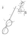
- Figure 1 shows a commercial glasses 1 with a left Temples 2 and a right temple 3.
- a left temples 2 At the back End of the right eyeglass temple 3 is in the usual way Carrying body 4 pushed from plastic.
- the support body 4 is bent over the front part of the eyeglass temple 3, so that the right temple 3 with worn glasses behind the ear grabs and holds the glasses.
- right temple 3 In contrast to right temple 3 is on the left temple 2 of the Carrying body removed, making the metal bendable temples tail 5 becomes visible.
- FIG. 1 further shows a hearing aid device 6 according to the invention.
- the housing of the hearing aid 6 has a relatively slim mid-range B and one in proportion to this enlarged front area A with a channel opening 7, in the attachment of the hearing aid 6 with the glasses. 1 the temples end piece 5 can be pushed.
- the hearing aid device 6 crossed by a correspondingly sized channel 8.
- the channel 8 could also be made from a cavity inside the hearing aid and a short, on the eyeglass tail closely fitting channel piece consist, the Guiding and fastening of the eyeglass temple end piece is used.
- the hearing aid device 6 comprises Furthermore, a microphone 9 with a sound inlet opening 10th for recording an acoustic input signal and conversion in an electrical signal.
- a signal processing unit 11 processing and frequency-dependent amplification occur the electrical signal.
- a handset 12 converts that processed electrical signal back into an acoustic Signal, which via a sound tube 13 and an earmold 14 passed into the ear canal of a hearing aid wearer becomes.
- To power the hearing aid 6 serves a battery, which is located in a battery compartment 15. Furthermore, via a volume control 16, the volume set or the hearing aid 6 off become.
- At least the middle region B of the hearing aid device 6 is off made of a plastically deformable material, e.g. made of silicone rubber, so that the housing in this area according to bent to the individual requirements of the hearing aid wearer can be.
- a plastically deformable material e.g. made of silicone rubber
- FIG. 1 they are related to the function the hearing aid 6 essential components (microphone 9, handset 12, signal processing unit 11, battery compartment 15) in the front part A and in the rear part C of the Hearing aid device 6.
- the middle area B are therefore located next to the channel 8 only connecting lines between the individual hearing aid components, making the case in this area opposite the enlarged front area A. or the enlarged rear portion C accordingly slim can be executed.
- FIG. 2 shows the glasses 1 according to Figure 1 with the attached thereto Hearing aid 6.
- Name and function of the individual Components correspond to the name and function according to FIG. 1.
- the housing of the Hearing aid 6 but no longer the elongated Shape as in Figure 1, but the housing is particularly in Center region B bent so that the hearing aid 6 at the left temple 2 the same function (holding the glasses) how the carrying body 4 on the right temple 3 takes over.
- the arrangement of the components of the hearing aid 6, as illustrated in Figures 1 and 2 has the Advantage that the central region B for bending the eyeglass temple end piece even can be heated. Also within the eyeglass temple end piece located in the housing contributes to this in that the hearing aid 6 after deformation its shape permanently (or possibly until a new adjustment).
- the invention offers the advantage that for the production of a Hearing glasses a standard glasses 1 can be used which is not damaged by the production of the hearing glasses becomes.
- the hearing aid wearer therefore has the option of different Try on glasses and glasses 1 after Loosen the hearing aid 6 back to its original Condition (with straps on both eyeglass tails) restore.
- the hearing aid according to the invention is not on the illustrated Design limited. Both with the glasses and with the hearing aid are within the scope of the invention, many variations conceivable. Of course, the hearing glasses also with two hearing aids according to the invention (depending one on the left and on the right temple) to the binaural Be equipped supply.
Landscapes
- Physics & Mathematics (AREA)
- Health & Medical Sciences (AREA)
- General Physics & Mathematics (AREA)
- Ophthalmology & Optometry (AREA)
- Optics & Photonics (AREA)
- Acoustics & Sound (AREA)
- General Health & Medical Sciences (AREA)
- Otolaryngology (AREA)
- Eyeglasses (AREA)
- Details Of Audible-Bandwidth Transducers (AREA)
- Adornments (AREA)
Abstract
Description
Claims (6)
- An einem Brillenbügel (2) befestigbares Hörhilfegerät (6), gekennzeichnet durch einen das Hörhilfegerät (6) zumindest teilweise durchziehenden Kanal (8) zur Aufnahme eines biegbaren Brillenbügel-Endstücks (5) und durch ein zumindest in einem Teilbereich (B) biegbares Gehäuse.
- An einem Brillenbügel (2) befestigbares Hörhilfegerät (6) nach Anspruch 1, gekennzeichnet durch einen schlanken, biegbaren Mittelbereich (B) und einen im Vergleich zu diesem vergrößerten vorderen Bereich (A) mit einer Kanalöffnung (7), in die das Brillenbügel-Endstück (5) einführbar ist.
- An einem Brillenbügel (2) befestigbares Hörhilfegerät (6) nach Anspruch 1 oder 2, dadurch gekennzeichnet, dass in dem vergrößerten vorderen Bereich (A) wenigstens ein Mikrofon (9) zur Aufnahme eines akustischen Eingangssignals angeordnet ist.
- An einem Brillenbügel (2) befestigbares Hörhilfegerät (6) nach einem der Ansprüche 1 bis 3, dadurch gekennzeichnet , dass in dem vergrößerten vorderen Bereich (A) wenigstens ein Hörer (12) zur Abgabe eines akustischen Ausgangssignals angeordnet ist.
- An einem Brillenbügel (2) befestigbares Hörhilfegerät (6) nach einem der Ansprüche 1 bis 4, gekennzeichnet durch einen im Vergleich zu dem schlanken, biegbaren Mittelbereich (B) vergrößerten hinteren Bereich (C), in dem eine Spannungsquelle angeordnet ist.
- An einem Brillenbügel (2) befestigbares Hörhilfegerät (6) nach einem der Ansprüche 1 bis 5, gekennzeichnet durch ein zumindest in dem Mittelbereich (B) aus einem thermoplastischen Kunststoff gebildetes Gehäuse.
Applications Claiming Priority (2)
| Application Number | Priority Date | Filing Date | Title |
|---|---|---|---|
| DE10343010 | 2003-09-17 | ||
| DE10343010A DE10343010B3 (de) | 2003-09-17 | 2003-09-17 | An einem Brillenbügel befestigbares Hörhilfegerät |
Publications (2)
| Publication Number | Publication Date |
|---|---|
| EP1517170A1 true EP1517170A1 (de) | 2005-03-23 |
| EP1517170B1 EP1517170B1 (de) | 2010-11-03 |
Family
ID=34177795
Family Applications (1)
| Application Number | Title | Priority Date | Filing Date |
|---|---|---|---|
| EP04019231A Expired - Lifetime EP1517170B1 (de) | 2003-09-17 | 2004-08-12 | An einem Brillenbügel befestigbares Hörhilfegerät |
Country Status (5)
| Country | Link |
|---|---|
| US (1) | US7103192B2 (de) |
| EP (1) | EP1517170B1 (de) |
| AT (1) | ATE487157T1 (de) |
| DE (2) | DE10343010B3 (de) |
| DK (1) | DK1517170T3 (de) |
Cited By (2)
| Publication number | Priority date | Publication date | Assignee | Title |
|---|---|---|---|---|
| EP2233965A1 (de) | 2009-03-24 | 2010-09-29 | Bruckhoff Apparatebau GmbH | Hörgerätmodul und Hörbrille |
| CN107113486A (zh) * | 2014-10-30 | 2017-08-29 | 索尼公司 | 声音输出设备 |
Families Citing this family (19)
| Publication number | Priority date | Publication date | Assignee | Title |
|---|---|---|---|---|
| US7735996B2 (en) | 2005-05-24 | 2010-06-15 | Varibel B.V. | Connector assembly for connecting an earpiece of a hearing aid to glasses temple |
| EP1727393A1 (de) * | 2005-05-24 | 2006-11-29 | Varibel B.V. | Verbindungseinrichtung zum Verbinden eines Ohrpassstückes eines Hörgerätes mit einer Brillenfassung |
| EP2036395A1 (de) * | 2006-06-20 | 2009-03-18 | Widex A/S | Gehäuse für ein hörgerät, hörgerät und verfahren zum herstellen eines hörgeräts |
| FR2910135B1 (fr) * | 2006-12-14 | 2009-02-20 | Xavier Arthur Carriou | Procede d'extrusion de branche de lunette pour y loger un appareil auditif |
| DE102007028652A1 (de) * | 2007-06-21 | 2009-01-02 | Bruckhoff Apparatebau Gmbh | Hörbrille |
| EP2681610B1 (de) * | 2011-03-04 | 2016-06-08 | Silvietta S.R.L. | Zusammenschiebbare brille |
| US8918197B2 (en) | 2012-06-13 | 2014-12-23 | Avraham Suhami | Audio communication networks |
| US8543061B2 (en) | 2011-05-03 | 2013-09-24 | Suhami Associates Ltd | Cellphone managed hearing eyeglasses |
| JP5945426B2 (ja) * | 2012-02-06 | 2016-07-05 | オリンパス株式会社 | ウェアラブル機器取り付け用眼鏡モダン |
| EP3143460B1 (de) | 2014-05-12 | 2018-10-24 | Beausoleil | Gehäuse für die aufnahme eines hörgerät |
| US20170102560A1 (en) * | 2015-10-13 | 2017-04-13 | James V. Murphy | Hearing aid holder for use with eyewear |
| US20190132683A1 (en) | 2017-10-31 | 2019-05-02 | Starkey Laboratories, Inc. | Hearing device including a sensor and a method of forming same |
| CN114127846B (zh) | 2019-07-21 | 2025-09-12 | 纽安思听力有限公司 | 语音跟踪收听设备 |
| US10986452B1 (en) * | 2019-10-15 | 2021-04-20 | Richard Hilvers | Hearing aid mounting assembly |
| WO2021074818A1 (en) | 2019-10-16 | 2021-04-22 | Nuance Hearing Ltd. | Beamforming devices for hearing assistance |
| US12513446B1 (en) * | 2022-02-25 | 2025-12-30 | E-filliate, Inc. | Earbuds with turn wheel control |
| US12464296B2 (en) | 2023-09-28 | 2025-11-04 | Nuance Hearing Ltd. | Hearing aid with own-voice mitigation |
| US12452611B2 (en) | 2023-10-23 | 2025-10-21 | Nuance Hearing Ltd. | Feedback cancellation in a hearing aid device using tap coherence values |
| US12658870B2 (en) | 2024-04-24 | 2026-06-16 | Nuance Hearing Ltd. | Howl detection in an audio system |
Citations (6)
| Publication number | Priority date | Publication date | Assignee | Title |
|---|---|---|---|---|
| DE1724439U (de) * | 1956-01-25 | 1956-06-21 | Siemens Reiniger Werke Ag | Elektrische hoerhilfe. |
| US2999136A (en) * | 1956-01-06 | 1961-09-05 | Telex Inc | Spectacle hearing aid |
| US3000462A (en) * | 1954-01-18 | 1961-09-19 | Alonzo L Smith | Air-conduction hearing aid clamps |
| US3382327A (en) * | 1965-05-07 | 1968-05-07 | Non Slip Temple Company Inc | Hearing aid eyeglass frame |
| US3825700A (en) * | 1973-03-02 | 1974-07-23 | Sonotone Corp | Articulated hearing aid temple and behind-the-ear hearing aid element |
| DE4333559A1 (de) * | 1993-10-01 | 1995-04-06 | Werner Weber | Brille mit Hörgerät |
Family Cites Families (7)
| Publication number | Priority date | Publication date | Assignee | Title |
|---|---|---|---|---|
| GB1051687A (de) * | 1963-05-06 | |||
| DE8336526U1 (de) * | 1983-12-20 | 1985-10-03 | Optische Werke G. Rodenstock, 8000 München | Weichummantelter Brillenbügel-Ohrbereich |
| DE8706344U1 (de) * | 1987-05-04 | 1987-06-19 | Bruckhoff, Henning, 3000 Hannover | Hörbrille |
| DE8808620U1 (de) | 1988-07-05 | 1988-09-08 | Siemens AG, 1000 Berlin und 8000 München | Brillenadapter für ein Hinter-dem-Ohr-Hörgerät |
| WO1996013136A1 (en) * | 1992-02-14 | 1996-05-02 | Da Silva Jean Pierre M | Audio-adapted eyeglass retainer |
| US6176576B1 (en) * | 1997-06-06 | 2001-01-23 | Radians, Inc. | Eyewear supported by a wearer's concha of an ear |
| DE50202909D1 (de) * | 2001-02-16 | 2005-06-02 | Audifon Ag Zuerich | Hörgerät für den einbau in einem seitenbügel einer optischen brille |
-
2003
- 2003-09-17 DE DE10343010A patent/DE10343010B3/de not_active Expired - Fee Related
-
2004
- 2004-08-12 AT AT04019231T patent/ATE487157T1/de active
- 2004-08-12 EP EP04019231A patent/EP1517170B1/de not_active Expired - Lifetime
- 2004-08-12 DK DK04019231.2T patent/DK1517170T3/da active
- 2004-08-12 DE DE502004011843T patent/DE502004011843D1/de not_active Expired - Lifetime
- 2004-09-17 US US10/943,451 patent/US7103192B2/en not_active Expired - Fee Related
Patent Citations (6)
| Publication number | Priority date | Publication date | Assignee | Title |
|---|---|---|---|---|
| US3000462A (en) * | 1954-01-18 | 1961-09-19 | Alonzo L Smith | Air-conduction hearing aid clamps |
| US2999136A (en) * | 1956-01-06 | 1961-09-05 | Telex Inc | Spectacle hearing aid |
| DE1724439U (de) * | 1956-01-25 | 1956-06-21 | Siemens Reiniger Werke Ag | Elektrische hoerhilfe. |
| US3382327A (en) * | 1965-05-07 | 1968-05-07 | Non Slip Temple Company Inc | Hearing aid eyeglass frame |
| US3825700A (en) * | 1973-03-02 | 1974-07-23 | Sonotone Corp | Articulated hearing aid temple and behind-the-ear hearing aid element |
| DE4333559A1 (de) * | 1993-10-01 | 1995-04-06 | Werner Weber | Brille mit Hörgerät |
Cited By (4)
| Publication number | Priority date | Publication date | Assignee | Title |
|---|---|---|---|---|
| EP2233965A1 (de) | 2009-03-24 | 2010-09-29 | Bruckhoff Apparatebau GmbH | Hörgerätmodul und Hörbrille |
| DE102009014114A1 (de) | 2009-03-24 | 2010-10-07 | Bruckhoff Apparatebau Gmbh | Hörgerätmodul und Hörbrille |
| DE102009014114B4 (de) * | 2009-03-24 | 2015-07-23 | Bruckhoff Apparatebau Gmbh | Hörgerätmodul und Hörbrille |
| CN107113486A (zh) * | 2014-10-30 | 2017-08-29 | 索尼公司 | 声音输出设备 |
Also Published As
| Publication number | Publication date |
|---|---|
| ATE487157T1 (de) | 2010-11-15 |
| DE10343010B3 (de) | 2005-04-21 |
| US20050074137A1 (en) | 2005-04-07 |
| DK1517170T3 (da) | 2011-02-21 |
| EP1517170B1 (de) | 2010-11-03 |
| US7103192B2 (en) | 2006-09-05 |
| DE502004011843D1 (de) | 2010-12-16 |
Similar Documents
| Publication | Publication Date | Title |
|---|---|---|
| DE10343010B3 (de) | An einem Brillenbügel befestigbares Hörhilfegerät | |
| EP1046943B1 (de) | Hörhilfe | |
| DE102008017194B4 (de) | Hörvorrichtung zum Tragen in der Ohrmuschel mit individuellem Formteil und Verfahren zum Herstellen einer Hörvorrichtung | |
| EP3750329B1 (de) | Universal-adapter für hörgeräte und ohrhörer | |
| EP1874093A2 (de) | Hörgerät mit einer Befestigung für einen Hörerschlauch | |
| DE102007045315B3 (de) | Werkzeug zum Einsetzen eines Hörers einer Hörvorrichtung in einen Gehörgang | |
| EP2091270A1 (de) | Hörvorrichtung mit Batteriefachrastung | |
| DE102007014131A1 (de) | Hörgerät mit einer Befestigung eines Hörerschlauchs | |
| EP1962553A2 (de) | Hörvorrichtung mit magnetisch befestigter Batteriehalteeinrichtung | |
| EP2003930B1 (de) | Hörgerät mit am Gehäuserahmen befestigtem Anschlussstück | |
| DE102009038940B3 (de) | Knochenleitungshörgerät | |
| EP1967893B1 (de) | Knochenleitungsmodul zum Aufsetzen auf eine Brille, Knochenleitungshörgerät-Brille mit einem derartigen Modul und Verfahren zu ihrer Herstellung | |
| EP0695108A2 (de) | Hörgerät | |
| EP2360949A2 (de) | Hörerschlauch mit Zugentlastung sowie Hörhilfe | |
| EP1847868B1 (de) | Hinter-dem-Ohr-Hörgerät einschließlich Brillenadapter mit dünnem Schallschlauch | |
| EP2393310B1 (de) | Tief-Ohrkanal-Hörinstrument | |
| DE10050766A1 (de) | Otoplastik für Hinter-dem-Ohr (HdO)-Hörgeräte | |
| EP1909533A2 (de) | Schallleiter und Hörvorrichtung | |
| EP2056625A2 (de) | Hörhilfsgerät, insbesondere HdO-Hörgerät | |
| DE102018132445A1 (de) | Otoplastik und Verwendung einer Otoplastik | |
| EP2416595B1 (de) | Hörinstrument mit einteiligem Spritzguss-Gehäuse | |
| DE4230308C1 (en) | Hearing aid carried behind ear - has stirrup formed on housing frame carrying electrical and electromechanical components | |
| EP2227039A2 (de) | Hörvorrichtung mit einer Akustikeinheit und einem Schalenteil | |
| DE102005019994B4 (de) | Hörgerät | |
| EP2544464A1 (de) | Abformstruktur für eine Hörvorrichtung |
Legal Events
| Date | Code | Title | Description |
|---|---|---|---|
| PUAI | Public reference made under article 153(3) epc to a published international application that has entered the european phase |
Free format text: ORIGINAL CODE: 0009012 |
|
| AK | Designated contracting states |
Kind code of ref document: A1 Designated state(s): AT BE BG CH CY CZ DE DK EE ES FI FR GB GR HU IE IT LI LU MC NL PL PT RO SE SI SK TR |
|
| AX | Request for extension of the european patent |
Extension state: AL HR LT LV MK |
|
| 17P | Request for examination filed |
Effective date: 20050422 |
|
| AKX | Designation fees paid |
Designated state(s): AT BE BG CH CY CZ DE DK EE ES FI FR GB GR HU IE IT LI LU MC NL PL PT RO SE SI SK TR |
|
| 17Q | First examination report despatched |
Effective date: 20051118 |
|
| GRAP | Despatch of communication of intention to grant a patent |
Free format text: ORIGINAL CODE: EPIDOSNIGR1 |
|
| GRAS | Grant fee paid |
Free format text: ORIGINAL CODE: EPIDOSNIGR3 |
|
| GRAA | (expected) grant |
Free format text: ORIGINAL CODE: 0009210 |
|
| AK | Designated contracting states |
Kind code of ref document: B1 Designated state(s): AT BE BG CH CY CZ DE DK EE ES FI FR GB GR HU IE IT LI LU MC NL PL PT RO SE SI SK TR |
|
| REG | Reference to a national code |
Ref country code: GB Ref legal event code: FG4D Free format text: NOT ENGLISH |
|
| REG | Reference to a national code |
Ref country code: CH Ref legal event code: NV Representative=s name: SIEMENS SCHWEIZ AG Ref country code: CH Ref legal event code: EP |
|
| REG | Reference to a national code |
Ref country code: IE Ref legal event code: FG4D Free format text: LANGUAGE OF EP DOCUMENT: GERMAN |
|
| REF | Corresponds to: |
Ref document number: 502004011843 Country of ref document: DE Date of ref document: 20101216 Kind code of ref document: P |
|
| REG | Reference to a national code |
Ref country code: DK Ref legal event code: T3 |
|
| REG | Reference to a national code |
Ref country code: NL Ref legal event code: VDEP Effective date: 20101103 |
|
| REG | Reference to a national code |
Ref country code: IE Ref legal event code: FD4D |
|
| PG25 | Lapsed in a contracting state [announced via postgrant information from national office to epo] |
Ref country code: NL Free format text: LAPSE BECAUSE OF FAILURE TO SUBMIT A TRANSLATION OF THE DESCRIPTION OR TO PAY THE FEE WITHIN THE PRESCRIBED TIME-LIMIT Effective date: 20101103 Ref country code: SI Free format text: LAPSE BECAUSE OF FAILURE TO SUBMIT A TRANSLATION OF THE DESCRIPTION OR TO PAY THE FEE WITHIN THE PRESCRIBED TIME-LIMIT Effective date: 20101103 Ref country code: FI Free format text: LAPSE BECAUSE OF FAILURE TO SUBMIT A TRANSLATION OF THE DESCRIPTION OR TO PAY THE FEE WITHIN THE PRESCRIBED TIME-LIMIT Effective date: 20101103 Ref country code: SE Free format text: LAPSE BECAUSE OF FAILURE TO SUBMIT A TRANSLATION OF THE DESCRIPTION OR TO PAY THE FEE WITHIN THE PRESCRIBED TIME-LIMIT Effective date: 20101103 Ref country code: PT Free format text: LAPSE BECAUSE OF FAILURE TO SUBMIT A TRANSLATION OF THE DESCRIPTION OR TO PAY THE FEE WITHIN THE PRESCRIBED TIME-LIMIT Effective date: 20110303 Ref country code: BG Free format text: LAPSE BECAUSE OF FAILURE TO SUBMIT A TRANSLATION OF THE DESCRIPTION OR TO PAY THE FEE WITHIN THE PRESCRIBED TIME-LIMIT Effective date: 20110203 |
|
| PG25 | Lapsed in a contracting state [announced via postgrant information from national office to epo] |
Ref country code: GR Free format text: LAPSE BECAUSE OF FAILURE TO SUBMIT A TRANSLATION OF THE DESCRIPTION OR TO PAY THE FEE WITHIN THE PRESCRIBED TIME-LIMIT Effective date: 20110204 |
|
| PG25 | Lapsed in a contracting state [announced via postgrant information from national office to epo] |
Ref country code: EE Free format text: LAPSE BECAUSE OF FAILURE TO SUBMIT A TRANSLATION OF THE DESCRIPTION OR TO PAY THE FEE WITHIN THE PRESCRIBED TIME-LIMIT Effective date: 20101103 Ref country code: ES Free format text: LAPSE BECAUSE OF FAILURE TO SUBMIT A TRANSLATION OF THE DESCRIPTION OR TO PAY THE FEE WITHIN THE PRESCRIBED TIME-LIMIT Effective date: 20110214 Ref country code: CZ Free format text: LAPSE BECAUSE OF FAILURE TO SUBMIT A TRANSLATION OF THE DESCRIPTION OR TO PAY THE FEE WITHIN THE PRESCRIBED TIME-LIMIT Effective date: 20101103 Ref country code: IE Free format text: LAPSE BECAUSE OF FAILURE TO SUBMIT A TRANSLATION OF THE DESCRIPTION OR TO PAY THE FEE WITHIN THE PRESCRIBED TIME-LIMIT Effective date: 20101103 |
|
| PG25 | Lapsed in a contracting state [announced via postgrant information from national office to epo] |
Ref country code: RO Free format text: LAPSE BECAUSE OF FAILURE TO SUBMIT A TRANSLATION OF THE DESCRIPTION OR TO PAY THE FEE WITHIN THE PRESCRIBED TIME-LIMIT Effective date: 20101103 Ref country code: PL Free format text: LAPSE BECAUSE OF FAILURE TO SUBMIT A TRANSLATION OF THE DESCRIPTION OR TO PAY THE FEE WITHIN THE PRESCRIBED TIME-LIMIT Effective date: 20101103 Ref country code: SK Free format text: LAPSE BECAUSE OF FAILURE TO SUBMIT A TRANSLATION OF THE DESCRIPTION OR TO PAY THE FEE WITHIN THE PRESCRIBED TIME-LIMIT Effective date: 20101103 |
|
| PLBE | No opposition filed within time limit |
Free format text: ORIGINAL CODE: 0009261 |
|
| STAA | Information on the status of an ep patent application or granted ep patent |
Free format text: STATUS: NO OPPOSITION FILED WITHIN TIME LIMIT |
|
| 26N | No opposition filed |
Effective date: 20110804 |
|
| PGFP | Annual fee paid to national office [announced via postgrant information from national office to epo] |
Ref country code: DK Payment date: 20110822 Year of fee payment: 8 |
|
| REG | Reference to a national code |
Ref country code: DE Ref legal event code: R097 Ref document number: 502004011843 Country of ref document: DE Effective date: 20110804 |
|
| PG25 | Lapsed in a contracting state [announced via postgrant information from national office to epo] |
Ref country code: IT Free format text: LAPSE BECAUSE OF FAILURE TO SUBMIT A TRANSLATION OF THE DESCRIPTION OR TO PAY THE FEE WITHIN THE PRESCRIBED TIME-LIMIT Effective date: 20101103 |
|
| BERE | Be: lapsed |
Owner name: SIEMENS AUDIOLOGISCHE TECHNIK G.M.B.H. Effective date: 20110831 |
|
| PG25 | Lapsed in a contracting state [announced via postgrant information from national office to epo] |
Ref country code: MC Free format text: LAPSE BECAUSE OF NON-PAYMENT OF DUE FEES Effective date: 20110831 |
|
| PG25 | Lapsed in a contracting state [announced via postgrant information from national office to epo] |
Ref country code: BE Free format text: LAPSE BECAUSE OF NON-PAYMENT OF DUE FEES Effective date: 20110831 |
|
| PGFP | Annual fee paid to national office [announced via postgrant information from national office to epo] |
Ref country code: GB Payment date: 20120809 Year of fee payment: 9 |
|
| REG | Reference to a national code |
Ref country code: AT Ref legal event code: MM01 Ref document number: 487157 Country of ref document: AT Kind code of ref document: T Effective date: 20110812 |
|
| PGFP | Annual fee paid to national office [announced via postgrant information from national office to epo] |
Ref country code: FR Payment date: 20120823 Year of fee payment: 9 |
|
| PG25 | Lapsed in a contracting state [announced via postgrant information from national office to epo] |
Ref country code: AT Free format text: LAPSE BECAUSE OF NON-PAYMENT OF DUE FEES Effective date: 20110812 |
|
| PGFP | Annual fee paid to national office [announced via postgrant information from national office to epo] |
Ref country code: DE Payment date: 20121019 Year of fee payment: 9 Ref country code: CH Payment date: 20121113 Year of fee payment: 9 |
|
| PG25 | Lapsed in a contracting state [announced via postgrant information from national office to epo] |
Ref country code: LU Free format text: LAPSE BECAUSE OF NON-PAYMENT OF DUE FEES Effective date: 20110812 Ref country code: CY Free format text: LAPSE BECAUSE OF EXPIRATION OF PROTECTION Effective date: 20101103 |
|
| PG25 | Lapsed in a contracting state [announced via postgrant information from national office to epo] |
Ref country code: TR Free format text: LAPSE BECAUSE OF FAILURE TO SUBMIT A TRANSLATION OF THE DESCRIPTION OR TO PAY THE FEE WITHIN THE PRESCRIBED TIME-LIMIT Effective date: 20101103 |
|
| PG25 | Lapsed in a contracting state [announced via postgrant information from national office to epo] |
Ref country code: HU Free format text: LAPSE BECAUSE OF FAILURE TO SUBMIT A TRANSLATION OF THE DESCRIPTION OR TO PAY THE FEE WITHIN THE PRESCRIBED TIME-LIMIT Effective date: 20101103 |
|
| REG | Reference to a national code |
Ref country code: DK Ref legal event code: EBP Effective date: 20130831 Ref country code: CH Ref legal event code: PL |
|
| GBPC | Gb: european patent ceased through non-payment of renewal fee |
Effective date: 20130812 |
|
| PG25 | Lapsed in a contracting state [announced via postgrant information from national office to epo] |
Ref country code: LI Free format text: LAPSE BECAUSE OF NON-PAYMENT OF DUE FEES Effective date: 20130831 Ref country code: CH Free format text: LAPSE BECAUSE OF NON-PAYMENT OF DUE FEES Effective date: 20130831 Ref country code: DE Free format text: LAPSE BECAUSE OF NON-PAYMENT OF DUE FEES Effective date: 20140301 |
|
| REG | Reference to a national code |
Ref country code: DE Ref legal event code: R119 Ref document number: 502004011843 Country of ref document: DE Effective date: 20140301 |
|
| REG | Reference to a national code |
Ref country code: FR Ref legal event code: ST Effective date: 20140430 |
|
| PG25 | Lapsed in a contracting state [announced via postgrant information from national office to epo] |
Ref country code: GB Free format text: LAPSE BECAUSE OF NON-PAYMENT OF DUE FEES Effective date: 20130812 |
|
| PG25 | Lapsed in a contracting state [announced via postgrant information from national office to epo] |
Ref country code: FR Free format text: LAPSE BECAUSE OF NON-PAYMENT OF DUE FEES Effective date: 20130902 |
|
| PG25 | Lapsed in a contracting state [announced via postgrant information from national office to epo] |
Ref country code: DK Free format text: LAPSE BECAUSE OF NON-PAYMENT OF DUE FEES Effective date: 20130831 |