EP1517010B1 - Ventilteller - Google Patents
Ventilteller Download PDFInfo
- Publication number
- EP1517010B1 EP1517010B1 EP04019998A EP04019998A EP1517010B1 EP 1517010 B1 EP1517010 B1 EP 1517010B1 EP 04019998 A EP04019998 A EP 04019998A EP 04019998 A EP04019998 A EP 04019998A EP 1517010 B1 EP1517010 B1 EP 1517010B1
- Authority
- EP
- European Patent Office
- Prior art keywords
- plies
- valve disc
- sealing layer
- disc
- disc according
- Prior art date
- Legal status (The legal status is an assumption and is not a legal conclusion. Google has not performed a legal analysis and makes no representation as to the accuracy of the status listed.)
- Expired - Lifetime
Links
- 238000007789 sealing Methods 0.000 claims abstract description 18
- ATJFFYVFTNAWJD-UHFFFAOYSA-N Tin Chemical compound [Sn] ATJFFYVFTNAWJD-UHFFFAOYSA-N 0.000 claims description 6
- 238000010438 heat treatment Methods 0.000 claims description 4
- 239000002985 plastic film Substances 0.000 claims description 4
- 229920006255 plastic film Polymers 0.000 claims description 4
- 238000010073 coating (rubber) Methods 0.000 claims description 3
- 238000007654 immersion Methods 0.000 claims description 3
- 239000002184 metal Substances 0.000 claims description 3
- 239000004743 Polypropylene Substances 0.000 claims description 2
- 239000000853 adhesive Substances 0.000 claims description 2
- 239000004922 lacquer Substances 0.000 claims description 2
- 230000008018 melting Effects 0.000 claims description 2
- 238000002844 melting Methods 0.000 claims description 2
- 239000004033 plastic Substances 0.000 claims description 2
- -1 polypropylene Polymers 0.000 claims description 2
- 229920001155 polypropylene Polymers 0.000 claims description 2
- 239000011344 liquid material Substances 0.000 claims 2
- 239000000463 material Substances 0.000 claims 1
- 238000007493 shaping process Methods 0.000 claims 1
- 230000002093 peripheral effect Effects 0.000 abstract 1
- 238000004519 manufacturing process Methods 0.000 description 4
- 230000004927 fusion Effects 0.000 description 2
- 239000007788 liquid Substances 0.000 description 2
- 239000000126 substance Substances 0.000 description 2
- 230000003746 surface roughness Effects 0.000 description 2
- 238000005476 soldering Methods 0.000 description 1
- 238000003466 welding Methods 0.000 description 1
Images
Classifications
-
- B—PERFORMING OPERATIONS; TRANSPORTING
- B65—CONVEYING; PACKING; STORING; HANDLING THIN OR FILAMENTARY MATERIAL
- B65D—CONTAINERS FOR STORAGE OR TRANSPORT OF ARTICLES OR MATERIALS, e.g. BAGS, BARRELS, BOTTLES, BOXES, CANS, CARTONS, CRATES, DRUMS, JARS, TANKS, HOPPERS, FORWARDING CONTAINERS; ACCESSORIES, CLOSURES, OR FITTINGS THEREFOR; PACKAGING ELEMENTS; PACKAGES
- B65D83/00—Containers or packages with special means for dispensing contents
- B65D83/14—Containers for dispensing liquid or semi-liquid contents by internal gaseous pressure, i.e. aerosol containers comprising propellant
- B65D83/38—Details of the container body
Definitions
- the present invention relates to a valve disk according to the preamble of claim 1.
- Such a valve disk is known from DE 33 17 809 A1.
- valve disks on the one hand form a closure for a container and on the other hand serve to receive a valve, are mounted on containers which are filled with a pressurized medium.
- the present invention is therefore based on the object to develop a valve disk of the generic type so that an unwanted outflow of preferably gas is excluded from the filled container.
- valve disk having the features of claim 1.
- the existing microintermediate space formed by the surface roughness is hermetically filled in such a way that gas molecules are prevented from flowing through.
- the new valve disk has properties such as a one-piece part, without restricting the particular manufacturing advantages that brings the production of several layers with it.
- the new valve plate is so dense that no measurable gas leakage is observed.
- a gas-tight sealing layer may be provided a film which is applied on one side of the two blank pieces before deformation.
- plastic film to use a self-adhesive, such as polypropylene, with a metal sheet from which a layer of the blank pieces is made, is coated.
- a self-adhesive such as polypropylene
- the sheet may also be coated with a rubber coating, wherein in both cases by the deformation or the deformation forces in the manufacture of the valve disk, the respective sealing layer practically flows into the existing surface depressions.
- the sealing layer in an initially liquid form, for example as a lacquer or as a suitable plastic, which cure after application and fill in the surface depressions.
- an initially liquid form for example as a lacquer or as a suitable plastic, which cure after application and fill in the surface depressions.
- the dish layers which have been deformed together to form a plate dome, are placed in a corresponding immersion bath. Due to the capillary effect, the liquid substance enters the microinterspace and then hardens. Prerequisite is a correspondingly low viscosity of the substance.
- the solution of the object of the invention according to claim 2 takes advantage of the fact that in principle, the formed of sheet metal, superimposed blank pieces are tinned. As a result of the heat application, at least in the area of the plate dome, a fusion of the tin layers takes place, as a result of which a gas-tight bond is produced between the blank pieces.
- the sealing layer is formed by the tin layers bonded together in the sense of welding.
- a heat application of the valve disk for the purpose of melting the tin layers is sufficient in a partial region of the valve disk which, however, extends extends over the full extent, so that a hermetic seal is ensured in the outflow of the gas.
- the invention is to be realized with little manufacturing effort, which is significant insofar as such valve disks are produced in very large numbers.
- the valve disk shown in FIG. 1 comprises a total of two disk layers, namely an inner disk layer 1 and an outer disk layer 2.
- the valve disk is formed by jointly deforming two blank pieces, between which a sealing layer 6 is arranged.
- This sealing layer 6 may be provided on both plate layers 1, 2, as is the case for example when using a tinned sheet.
- the sealing layer 6 can also be applied to one of the two plate layers 1, 2, but in any case on the side of a plate layer 1, 2, which faces the other.
- Such a sealing layer 6 is applied, for example, as a gas-tight plastic film or as a rubber coating, which at least largely fills the existing surface depressions of the dish layers 1, 2 in the contact area after the deformation to the valve disk.
- This effect is achieved by filling existing surface depressions 7 of the plate layers 1, 2, so that no gas can pass from the interior of the container.
Landscapes
- Chemical & Material Sciences (AREA)
- Dispersion Chemistry (AREA)
- Engineering & Computer Science (AREA)
- Mechanical Engineering (AREA)
- Filling Or Discharging Of Gas Storage Vessels (AREA)
- Check Valves (AREA)
- Packaging For Recording Disks (AREA)
- Valve-Gear Or Valve Arrangements (AREA)
- Compressor (AREA)
- Self-Closing Valves And Venting Or Aerating Valves (AREA)
- Sliding Valves (AREA)
- Gas Exhaust Devices For Batteries (AREA)
Description
- Die vorliegende Erfindung betrifft einen Ventilteller gemäß dem Oberbegriff des Anspruchs 1.
- Ein derartiger Ventilteller ist aus der DE 33 17 809 A1 bekannt.
- Solche Ventilteller, die einerseits einen Verschluß für ein Behältnis bilden und andererseits der Aufnahme eines Ventils dienen, werden an Behältnissen montiert, die mit einem unter Druck stehenden Medium befüllt sind.
- Insbesondere bei Befüllung mit einem Gas, beispielsweise zum Betrieb einer Camping-Kochstelle oder einer Löteinrichtung, ergeben sich beim Einsatz der Ventilteller Probleme, da die aneinander liegenden, zu einem Ventilteller geformten Zuschnittstücke nicht gasdicht miteinander verbunden sind.
- Durch die Oberflächenrauhigkeit sind zwischen den beiden Lagen Mikrozwischenräume vorhanden, durch die das unter Druck stehende Gas aus dem Inneren des Behältnisses entweichen kann.
- Zwar ist die Menge des entweichenden Gases, bezogen auf eine Zeiteinheit, relativ gering, da jedoch ein Ausstrom ständig erfolgt, entweicht insgesamt gesehen über den gesamten Nutzungszeitraum des Behältnisses eine nicht unerhebliche Menge so daß das tatsächlich nutzbare Gasvolumen nur einen entsprechenden Anteil ausmacht.
- Diesem Umstand kommt vor allem deshalb eine besondere Bedeutung zu, als die Behältnisse für den genannten Verwendungszweck in großen Stückzahlen zum Einsatz kommen, wodurch sich natürlich ein entsprechender wirtschaftlicher Schaden ergibt.
- Der vorliegenden Erfindung liegt daher die Aufgabe zugrunde, einen Ventilteller der gattungsgemäßen Art so weiter zu entwickeln, daß ein ungewolltes Ausströmen von vorzugsweise Gas aus dem befüllten Behältnis ausgeschlossen ist.
- Diese Aufgabe wird durch einen Ventilteller gelöst, der die Merkmale des Anspruchs 1 aufweist.
- Mit Hilfe der zwischen zwei Zwischenstücken vollflächig angeordneten Dichtungsschicht wird der vorhandene, durch die Oberflächenrauhigkeit gebildete Mikrozwischenraum so hermetisch verfüllt, daß das Durchströmen von Gasmolekülen ausgeschlossen ist.
- Der neue Ventilteller besitzt insoweit Eigenschaften wie ein einstückiges Teil, ohne die insbesondere fertigungstechnischen Vorteile, die die Herstellung aus mehreren Lagen mit sich bringt, einzuschränken.
- Selbst über einen langen Zeitraum ist der neue Ventilteller so dicht, daß kein meßbarer Gasaustritt festzustellen ist.
- Aus den in der Beschreibungseinleitung genannten Gründen ergibt sich eine ganze Reihe von Vorteilen durch die Erfindung, von denen insbesondere der wirtschaftliche Aspekt zu nennen ist, da das in das Behältnis eingebrachte Gasvolumen vollständig nutzbar ist.
- Als gasdichte Dichtungsschicht kann eine Folie vorgesehen sein, die auf einer Seite der beiden Zuschnittsstücke vor der Verformung aufgebracht ist.
- Dabei ist nach einem weiteren Gedanken vorgesehen, als Kunststofffolie eine selbsthaftende einzusetzen, beispielsweise Polypropylen, mit der eine Blechtafel, aus der eine Lage der Zuschnittsstücke gefertigt wird, beschichtet ist.
- Statt einer Kunststofffolie kann das Blech auch mit einer Gummierung beschichtet sein, wobei in beiden Fällen durch die Verformung bzw. die Verformungskräfte bei der Herstellung des Ventiltellers die jeweilige Dichtungsschicht praktisch in die vorhandenen Oberflächenvertiefungen einfließt.
- Ebenfalls denkbar ist die Dichtungsschicht in zunächst flüssiger Form aufzutragen, bspw. als Lack oder als geeigneter Kunststoff, die nach dem Auftrag aushärten und die Oberflächenvertiefungen ausfüllen. Zum Auftrag werden die zu einem Tellerdom gemeinsam verformten Tellerlagen in ein entsprechendes Tauchbad gegeben. Durch die Kapillarwirkung gelangt der flüssige Stoff in den Mikrozwischenraum und härtet danach aus. Voraussetzung ist eine entsprechend geringe Viskosität des Stoffes.
- Die Lösung der Aufgabe der Erfindung entsprechend dem Anspruch 2 macht sich zunutze, daß grundsätzlich die aus Blech gebildeten, aufeinander liegenden Zuschnittsstücke verzinnt sind. Durch die Wärmeaufbringung zumindest im Bereich des Tellerdomes erfolgt eine Verschmelzung der Zinnschichten, wodurch ein gasdichter Verbund zwischen den Zuschnittsstücken hergestellt wird. In diesem Fall wird die Dichtungsschicht durch die im Sinne eines Schweißens miteinander verbundenen Zinnschichten gebildet.
- Eine Wärmebeaufschlagung des Ventiltellers zum Zwecke des Schmelzens der Zinnschichten reicht in einem Teilbereich des Ventiltellers aus, der sich jedoch über den vollen Umfang erstreckt, so daß eine hermetische Abdichtung in Ausströmrichtung des Gases gewährleistet ist.
- Im übrigen ist die Erfindung mit geringem fertigungstechnischen Aufwand zu realisieren, was insofern von Bedeutung ist, als solche Ventilteller in sehr großen Stückzahlen hergestellt werden.
- Weitere vorteilhafte Ausbildungen der Erfindung sind in den Unteransprüchen gekennzeichnet.
- Ein Ausführungsbeispiel der Erfindung wird nachfolgend anhand der beigefügten Zeichnungen beschrieben.
- Es zeigen:
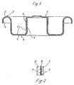
- Figur 1
- einen erfindungsgemäßen Ventilteller in einer geschnittenen Seitenansicht,
- Figur 2
- eine Einzelheit des Ventiltellers, ebenfalls in einer geschnittenen Seitenansicht.
- Der in der Figur 1 gezeigte Ventilteller besteht insgesamt aus zwei Tellerlagen, und zwar aus einer inneren Tellerlage 1 sowie einer äußeren Tellerlage 2.
- Der Ventilteller ist durch gemeinsames Verformen von zwei Zuschnittsstücken gebildet, zwischen denen eine Dichtungsschicht 6 angeordnet ist.
- Diese Dichtungsschicht 6 kann auf beiden Tellerlagen 1, 2 vorgesehen sein, wie dies beispielsweise beim Einsatz eines verzinnten Bleches der Fall ist.
- Statt dessen kann die Dichtungsschicht 6 auch auf eine der beiden Tellerlagen 1, 2 aufgebracht sein, in jedem Fall aber auf der Seite einer Tellerlage 1, 2, die der anderen zugewandt ist.
- Eine solche Dichtungsschicht 6 ist beispielsweise als gasdichte Kunststoffolie oder als Gummierung aufgebracht, die nach der Verformung zu dem Ventilteller die vorhandenen Oberflächenvertiefungen der Tellerlagen 1, 2 im Berührungsbereich zumindest weitgehend ausfüllt.
- Bei Einsatz von verzinnten Blechen als Zuschnittsstücke reicht eine Erwärmung im oberen, also im Kopfbereich eines Tellerdomes 5, der ebenso angeformt ist wie ein umlaufender Kragen 3, durch den der Ventilteller mit einem nicht dargestellten Behältnis verbindbar ist.
- Durch die Erwärmung im Kopfbereich des Tellerdomes 5, der sich ausgehend von einem radialen Tellerboden 4 axial erstreckt, wird ein Verschmelzen der beiden einander zugewandten Zinnschichten zu einer Dichtungsschicht erreicht, die sich über den gesamten Umfang des Tellerdomes 5 erstreckt. Auch hierdurch wird ein gasdichter Verbund der Tellerlagen 1, 2 erzielt.
- Dieser Effekt wird durch das Ausfüllen vorhandener Oberflächenvertiefungen 7 der Tellerlagen 1, 2 erreicht, so daß kein Gas aus dem Inneren des Behältnisses passieren kann.
-
- 1
- innere Tellerlage
- 2
- äußere Tellerlage
- 3
- Kragen
- 4
- Tellerboden
- 5
- Tellerdom
- 6
- Dichtungsschicht
- 7
- Oberflächenvertiefungen
Claims (11)
- Ventilteller mit einem Tellerdom (5), für ein vorzugsweise mit Gas befülltes Behältnis, der aus mindestens zwei Tellerlagen (1, 2) von gemeinsam verformten Zuschnittsstücken gebildet ist, dadurch gekennzeichnet, daß zwischen den Tellerlagen (1, 2) zumindest in einem vollumfänglichen Teilbereich eine gasdichte Dichtungsschicht (6) angeordnet ist, durch die vorhandene Oberflächenvertiefungen (7) der Tellerlagen (1, 2) zumindest weitgehend ausgefüllt sind.
- Ventilteller nach Anspruch 1, bei dem die Tellerlagen (1, 2) aus einem verzinnten Blech bestehen, dadurch gekennzeichnet, daß die Dichtungsschicht (6) durch zumindest partielles Erwärmen der verformten Tellerlagen (1, 2) und Schmelzen der Zinnschichten gebildet ist.
- Ventilteller nach Anspruch 2, dadurch gekennzeichnet, daß die Dichtungsschicht (6) durch Erwärmen des Kopfbereiches des Tellerdomes (5) gebildet ist.
- Ventilteller nach Anspruch 1, dadurch gekennzeichnet, daß die Dichtungsschicht (6) aus einer gasdichten Folie, vorzugsweise einer Kunststofffolie, besteht.
- Ventilteller nach Anspruch 4, dadurch gekennzeichnet, daß die Folie vor der Verformung der Zuschnittsstücke zumindest auf eine der zwei aneinander liegenden Lagen aufgebracht ist.
- Ventilteller nach einem der vorhergehenden Ansprüche, dadurch gekennzeichnet, daß als Dichtungsschicht (6) auf eine der Lagen der Zuschnittsstücke eine Gummierung aufgebracht ist.
- Ventilteller nach einem der vorhergehenden Ansprüche, dadurch gekennzeichnet, daß die aufgebrachte Folie selbsthaftend ist.
- Ventilteller nach einem der vorhergehenden Ansprüche, dadurch gekennzeichnet, daß die Folie aus Polypropylen besteht.
- Ventilteller nach einem der vorhergehenden Ansprüche, dadurch gekennzeichnet, daß die Dichtungsschicht (6) aus einem zunächst flüssigen, nach einem Einbringen zwischen die Tellerlagen (1, 2) ausgehärteten Stoff besteht.
- Ventilteller nach Anspruch 9, dadurch gekennzeichnet, daß der zunächst flüssige Stoff durch Tauchen der gemeinsam verformten Tellerlagen (1, 2) in ein entsprechendes Tauchbad aufgetragen ist.
- Ventilteller nach einem der vorhergehenden Ansprüche, dadurch gekennzeichnet, daß der Stoff aus einem Lack, einem Kunststoff oder dergleichen besteht.
Priority Applications (1)
| Application Number | Priority Date | Filing Date | Title |
|---|---|---|---|
| PL04019998T PL1517010T3 (pl) | 2003-09-20 | 2004-08-24 | Grzybek zaworu |
Applications Claiming Priority (2)
| Application Number | Priority Date | Filing Date | Title |
|---|---|---|---|
| DE10343629A DE10343629A1 (de) | 2003-09-20 | 2003-09-20 | Ventilteller |
| DE10343629 | 2003-09-20 |
Publications (3)
| Publication Number | Publication Date |
|---|---|
| EP1517010A2 EP1517010A2 (de) | 2005-03-23 |
| EP1517010A3 EP1517010A3 (de) | 2005-04-06 |
| EP1517010B1 true EP1517010B1 (de) | 2006-03-15 |
Family
ID=34177860
Family Applications (1)
| Application Number | Title | Priority Date | Filing Date |
|---|---|---|---|
| EP04019998A Expired - Lifetime EP1517010B1 (de) | 2003-09-20 | 2004-08-24 | Ventilteller |
Country Status (5)
| Country | Link |
|---|---|
| EP (1) | EP1517010B1 (de) |
| AT (1) | ATE320392T1 (de) |
| DE (2) | DE10343629A1 (de) |
| ES (1) | ES2260718T3 (de) |
| PL (1) | PL1517010T3 (de) |
Family Cites Families (4)
| Publication number | Priority date | Publication date | Assignee | Title |
|---|---|---|---|---|
| US3702669A (en) * | 1970-02-05 | 1972-11-14 | Ronald F Ewald | Aerosol container |
| ZA807387B (en) * | 1979-12-08 | 1981-11-25 | Metal Box Co Ltd | Containers |
| DE3317809C2 (de) * | 1983-05-17 | 1994-09-15 | Ewald Euscher Fa | Ventilteller für Behälterventile, sowie Verfahren zu seiner Herstellung |
| GB2145775B (en) * | 1983-08-31 | 1987-08-05 | Metal Box Plc | Pressurisable containers |
-
2003
- 2003-09-20 DE DE10343629A patent/DE10343629A1/de not_active Ceased
-
2004
- 2004-08-24 EP EP04019998A patent/EP1517010B1/de not_active Expired - Lifetime
- 2004-08-24 DE DE502004000349T patent/DE502004000349D1/de not_active Expired - Lifetime
- 2004-08-24 PL PL04019998T patent/PL1517010T3/pl unknown
- 2004-08-24 AT AT04019998T patent/ATE320392T1/de not_active IP Right Cessation
- 2004-08-24 ES ES04019998T patent/ES2260718T3/es not_active Expired - Lifetime
Also Published As
| Publication number | Publication date |
|---|---|
| PL1517010T3 (pl) | 2006-07-31 |
| ATE320392T1 (de) | 2006-04-15 |
| ES2260718T3 (es) | 2006-11-01 |
| DE502004000349D1 (de) | 2006-05-11 |
| EP1517010A2 (de) | 2005-03-23 |
| DE10343629A1 (de) | 2005-04-14 |
| EP1517010A3 (de) | 2005-04-06 |
Similar Documents
| Publication | Publication Date | Title |
|---|---|---|
| DE69214107T2 (de) | Ausgabebehälter für eine viskose Flüssigkeit | |
| DE3802314C1 (de) | ||
| CH682480A5 (de) | Verpackungstube. | |
| DE3012342A1 (de) | Mehrschichtfolie fuer den verschluss von gefaessen | |
| EP1062397B1 (de) | Doppellagenblech aus zwei deckblechen und einer zwischenlage | |
| DE1877377U (de) | Kronenkappe mit dichtungsring. | |
| EP1414706B1 (de) | Verfahren zur Herstellung eines Verpackungsbehälters | |
| EP3482431A1 (de) | Gehäuseteil einer batteriezelle oder für eine batteriezelle sowie verfahren zum applizieren eines berstelements an einem gehäuseteil einer batteriezelle | |
| EP1227987A1 (de) | Behälter mit innenbeutel | |
| EP0819086A1 (de) | Dose mit einer verschlussmembran aus folie, sowie verfahren, vorrichtung und folie zur herstellung der dose | |
| DE102017004657A1 (de) | Behälter mit Innenbeutel | |
| EP1517010B1 (de) | Ventilteller | |
| DE1281514B (de) | Verfahren zur Herstellung einer druckfesten und gasdichten Verbindung zwischen einerporoesen Scheibe und ihrer Halterung | |
| EP3789318B1 (de) | Verfahren zur herstellung einer getränkekapsel mit dichtring | |
| DE2162307A1 (de) | Druckbehälter | |
| CH653305A5 (de) | Verfahren zum herstellen eines dosendeckels. | |
| EP1271043B1 (de) | Arbeitsverfahren zur Abdichtung von Leckagen | |
| EP1401644B1 (de) | Zu einem formbauteil umformbare blechplatine | |
| DE2915118C2 (de) | Verfahren zum Aufbringen einer mit einem thermoplastischen Material beschichteten Folie auf einen aus nicht thermoplastischem Material bestehenden Behälter und Vorrichtung zur Durchführung des Verfahrens | |
| EP1106277B1 (de) | Druckluftbehälter | |
| DE102018203324B4 (de) | Verfahren zur Herstellung eines Gasgenerators und Gasgenerator | |
| DE19621617C2 (de) | Verfahren zur Herstellung eines Schraubdeckels | |
| DE102007000244A1 (de) | Druckgasbehälter, insbesondere für Fahrzeuge, und ein Verfahren zu dessen Herstellung | |
| US2433806A (en) | Process for making containers | |
| DE102014113202A1 (de) | Verschlussvorrichtung für einen Behälter |
Legal Events
| Date | Code | Title | Description |
|---|---|---|---|
| PUAI | Public reference made under article 153(3) epc to a published international application that has entered the european phase |
Free format text: ORIGINAL CODE: 0009012 |
|
| PUAL | Search report despatched |
Free format text: ORIGINAL CODE: 0009013 |
|
| AK | Designated contracting states |
Kind code of ref document: A2 Designated state(s): AT BE BG CH CY CZ DE DK EE ES FI FR GB GR HU IE IT LI LU MC NL PL PT RO SE SI SK TR |
|
| AX | Request for extension of the european patent |
Extension state: AL HR LT LV MK |
|
| AK | Designated contracting states |
Kind code of ref document: A3 Designated state(s): AT BE BG CH CY CZ DE DK EE ES FI FR GB GR HU IE IT LI LU MC NL PL PT RO SE SI SK TR |
|
| AX | Request for extension of the european patent |
Extension state: AL HR LT LV MK |
|
| RIC1 | Information provided on ipc code assigned before grant |
Ipc: 7B 65D 83/14 A |
|
| 17P | Request for examination filed |
Effective date: 20050312 |
|
| GRAP | Despatch of communication of intention to grant a patent |
Free format text: ORIGINAL CODE: EPIDOSNIGR1 |
|
| GRAS | Grant fee paid |
Free format text: ORIGINAL CODE: EPIDOSNIGR3 |
|
| RAP1 | Party data changed (applicant data changed or rights of an application transferred) |
Owner name: EWALD EUSCHER GMBH & CO. KG |
|
| AKX | Designation fees paid |
Designated state(s): AT BE BG CH CY CZ DE DK EE ES FI FR GB GR HU IE IT LI LU MC NL PL PT RO SE SI SK TR |
|
| GRAA | (expected) grant |
Free format text: ORIGINAL CODE: 0009210 |
|
| AK | Designated contracting states |
Kind code of ref document: B1 Designated state(s): AT BE BG CH CY CZ DE DK EE ES FI FR GB GR HU IE IT LI LU MC NL PL PT RO SE SI SK TR |
|
| PG25 | Lapsed in a contracting state [announced via postgrant information from national office to epo] |
Ref country code: RO Free format text: LAPSE BECAUSE OF FAILURE TO SUBMIT A TRANSLATION OF THE DESCRIPTION OR TO PAY THE FEE WITHIN THE PRESCRIBED TIME-LIMIT Effective date: 20060315 Ref country code: SK Free format text: LAPSE BECAUSE OF FAILURE TO SUBMIT A TRANSLATION OF THE DESCRIPTION OR TO PAY THE FEE WITHIN THE PRESCRIBED TIME-LIMIT Effective date: 20060315 Ref country code: IE Free format text: LAPSE BECAUSE OF FAILURE TO SUBMIT A TRANSLATION OF THE DESCRIPTION OR TO PAY THE FEE WITHIN THE PRESCRIBED TIME-LIMIT Effective date: 20060315 Ref country code: NL Free format text: LAPSE BECAUSE OF FAILURE TO SUBMIT A TRANSLATION OF THE DESCRIPTION OR TO PAY THE FEE WITHIN THE PRESCRIBED TIME-LIMIT Effective date: 20060315 Ref country code: FI Free format text: LAPSE BECAUSE OF FAILURE TO SUBMIT A TRANSLATION OF THE DESCRIPTION OR TO PAY THE FEE WITHIN THE PRESCRIBED TIME-LIMIT Effective date: 20060315 Ref country code: SI Free format text: LAPSE BECAUSE OF FAILURE TO SUBMIT A TRANSLATION OF THE DESCRIPTION OR TO PAY THE FEE WITHIN THE PRESCRIBED TIME-LIMIT Effective date: 20060315 |
|
| REG | Reference to a national code |
Ref country code: GB Ref legal event code: FG4D Free format text: NOT ENGLISH Ref country code: CH Ref legal event code: EP |
|
| REG | Reference to a national code |
Ref country code: IE Ref legal event code: FG4D Free format text: LANGUAGE OF EP DOCUMENT: GERMAN |
|
| REF | Corresponds to: |
Ref document number: 502004000349 Country of ref document: DE Date of ref document: 20060511 Kind code of ref document: P |
|
| PG25 | Lapsed in a contracting state [announced via postgrant information from national office to epo] |
Ref country code: BG Free format text: LAPSE BECAUSE OF FAILURE TO SUBMIT A TRANSLATION OF THE DESCRIPTION OR TO PAY THE FEE WITHIN THE PRESCRIBED TIME-LIMIT Effective date: 20060615 Ref country code: DK Free format text: LAPSE BECAUSE OF FAILURE TO SUBMIT A TRANSLATION OF THE DESCRIPTION OR TO PAY THE FEE WITHIN THE PRESCRIBED TIME-LIMIT Effective date: 20060615 Ref country code: SE Free format text: LAPSE BECAUSE OF FAILURE TO SUBMIT A TRANSLATION OF THE DESCRIPTION OR TO PAY THE FEE WITHIN THE PRESCRIBED TIME-LIMIT Effective date: 20060615 |
|
| GBT | Gb: translation of ep patent filed (gb section 77(6)(a)/1977) |
Effective date: 20060530 |
|
| PG25 | Lapsed in a contracting state [announced via postgrant information from national office to epo] |
Ref country code: PT Free format text: LAPSE BECAUSE OF FAILURE TO SUBMIT A TRANSLATION OF THE DESCRIPTION OR TO PAY THE FEE WITHIN THE PRESCRIBED TIME-LIMIT Effective date: 20060816 |
|
| PG25 | Lapsed in a contracting state [announced via postgrant information from national office to epo] |
Ref country code: MC Free format text: LAPSE BECAUSE OF NON-PAYMENT OF DUE FEES Effective date: 20060831 Ref country code: BE Free format text: LAPSE BECAUSE OF NON-PAYMENT OF DUE FEES Effective date: 20060831 |
|
| NLV1 | Nl: lapsed or annulled due to failure to fulfill the requirements of art. 29p and 29m of the patents act | ||
| REG | Reference to a national code |
Ref country code: IE Ref legal event code: FD4D |
|
| REG | Reference to a national code |
Ref country code: ES Ref legal event code: FG2A Ref document number: 2260718 Country of ref document: ES Kind code of ref document: T3 |
|
| ET | Fr: translation filed | ||
| PLBE | No opposition filed within time limit |
Free format text: ORIGINAL CODE: 0009261 |
|
| STAA | Information on the status of an ep patent application or granted ep patent |
Free format text: STATUS: NO OPPOSITION FILED WITHIN TIME LIMIT |
|
| 26N | No opposition filed |
Effective date: 20061218 |
|
| PG25 | Lapsed in a contracting state [announced via postgrant information from national office to epo] |
Ref country code: AT Free format text: LAPSE BECAUSE OF NON-PAYMENT OF DUE FEES Effective date: 20060824 |
|
| BERE | Be: lapsed |
Owner name: EWALD EUSCHER G.M.B.H. & CO. KG Effective date: 20060831 |
|
| PG25 | Lapsed in a contracting state [announced via postgrant information from national office to epo] |
Ref country code: GR Free format text: LAPSE BECAUSE OF FAILURE TO SUBMIT A TRANSLATION OF THE DESCRIPTION OR TO PAY THE FEE WITHIN THE PRESCRIBED TIME-LIMIT Effective date: 20060616 Ref country code: CZ Free format text: LAPSE BECAUSE OF FAILURE TO SUBMIT A TRANSLATION OF THE DESCRIPTION OR TO PAY THE FEE WITHIN THE PRESCRIBED TIME-LIMIT Effective date: 20060315 |
|
| PG25 | Lapsed in a contracting state [announced via postgrant information from national office to epo] |
Ref country code: EE Free format text: LAPSE BECAUSE OF FAILURE TO SUBMIT A TRANSLATION OF THE DESCRIPTION OR TO PAY THE FEE WITHIN THE PRESCRIBED TIME-LIMIT Effective date: 20060315 |
|
| PG25 | Lapsed in a contracting state [announced via postgrant information from national office to epo] |
Ref country code: LU Free format text: LAPSE BECAUSE OF NON-PAYMENT OF DUE FEES Effective date: 20060824 Ref country code: TR Free format text: LAPSE BECAUSE OF FAILURE TO SUBMIT A TRANSLATION OF THE DESCRIPTION OR TO PAY THE FEE WITHIN THE PRESCRIBED TIME-LIMIT Effective date: 20060315 Ref country code: HU Free format text: LAPSE BECAUSE OF FAILURE TO SUBMIT A TRANSLATION OF THE DESCRIPTION OR TO PAY THE FEE WITHIN THE PRESCRIBED TIME-LIMIT Effective date: 20060916 |
|
| PG25 | Lapsed in a contracting state [announced via postgrant information from national office to epo] |
Ref country code: CY Free format text: LAPSE BECAUSE OF FAILURE TO SUBMIT A TRANSLATION OF THE DESCRIPTION OR TO PAY THE FEE WITHIN THE PRESCRIBED TIME-LIMIT Effective date: 20060315 |
|
| REG | Reference to a national code |
Ref country code: CH Ref legal event code: PL |
|
| PG25 | Lapsed in a contracting state [announced via postgrant information from national office to epo] |
Ref country code: CH Free format text: LAPSE BECAUSE OF NON-PAYMENT OF DUE FEES Effective date: 20080831 Ref country code: LI Free format text: LAPSE BECAUSE OF NON-PAYMENT OF DUE FEES Effective date: 20080831 |
|
| PGFP | Annual fee paid to national office [announced via postgrant information from national office to epo] |
Ref country code: ES Payment date: 20100830 Year of fee payment: 7 |
|
| PGFP | Annual fee paid to national office [announced via postgrant information from national office to epo] |
Ref country code: DE Payment date: 20100809 Year of fee payment: 7 Ref country code: FR Payment date: 20100901 Year of fee payment: 7 Ref country code: IT Payment date: 20100825 Year of fee payment: 7 |
|
| PGFP | Annual fee paid to national office [announced via postgrant information from national office to epo] |
Ref country code: GB Payment date: 20100823 Year of fee payment: 7 Ref country code: PL Payment date: 20100727 Year of fee payment: 7 |
|
| GBPC | Gb: european patent ceased through non-payment of renewal fee |
Effective date: 20110824 |
|
| REG | Reference to a national code |
Ref country code: FR Ref legal event code: ST Effective date: 20120430 |
|
| PG25 | Lapsed in a contracting state [announced via postgrant information from national office to epo] |
Ref country code: IT Free format text: LAPSE BECAUSE OF NON-PAYMENT OF DUE FEES Effective date: 20110824 |
|
| REG | Reference to a national code |
Ref country code: DE Ref legal event code: R119 Ref document number: 502004000349 Country of ref document: DE Effective date: 20120301 |
|
| PG25 | Lapsed in a contracting state [announced via postgrant information from national office to epo] |
Ref country code: GB Free format text: LAPSE BECAUSE OF NON-PAYMENT OF DUE FEES Effective date: 20110824 Ref country code: FR Free format text: LAPSE BECAUSE OF NON-PAYMENT OF DUE FEES Effective date: 20110831 |
|
| PG25 | Lapsed in a contracting state [announced via postgrant information from national office to epo] |
Ref country code: PL Free format text: LAPSE BECAUSE OF NON-PAYMENT OF DUE FEES Effective date: 20110824 |
|
| REG | Reference to a national code |
Ref country code: ES Ref legal event code: FD2A Effective date: 20121207 |
|
| REG | Reference to a national code |
Ref country code: PL Ref legal event code: LAPE |
|
| PG25 | Lapsed in a contracting state [announced via postgrant information from national office to epo] |
Ref country code: ES Free format text: LAPSE BECAUSE OF NON-PAYMENT OF DUE FEES Effective date: 20110825 |
|
| PG25 | Lapsed in a contracting state [announced via postgrant information from national office to epo] |
Ref country code: DE Free format text: LAPSE BECAUSE OF NON-PAYMENT OF DUE FEES Effective date: 20120301 |