EP1516860B1 - Vorrichtung und Verfahren zum Herstellen von Glasfasern - Google Patents
Vorrichtung und Verfahren zum Herstellen von Glasfasern Download PDFInfo
- Publication number
- EP1516860B1 EP1516860B1 EP04022368.7A EP04022368A EP1516860B1 EP 1516860 B1 EP1516860 B1 EP 1516860B1 EP 04022368 A EP04022368 A EP 04022368A EP 1516860 B1 EP1516860 B1 EP 1516860B1
- Authority
- EP
- European Patent Office
- Prior art keywords
- heating
- glass fibers
- bushes
- preforms
- fiber
- Prior art date
- Legal status (The legal status is an assumption and is not a legal conclusion. Google has not performed a legal analysis and makes no representation as to the accuracy of the status listed.)
- Expired - Lifetime
Links
Images


Classifications
-
- C—CHEMISTRY; METALLURGY
- C03—GLASS; MINERAL OR SLAG WOOL
- C03B—MANUFACTURE, SHAPING, OR SUPPLEMENTARY PROCESSES
- C03B37/00—Manufacture or treatment of flakes, fibres, or filaments from softened glass, minerals, or slags
- C03B37/01—Manufacture of glass fibres or filaments
- C03B37/02—Manufacture of glass fibres or filaments by drawing or extruding, e.g. direct drawing of molten glass from nozzles; Cooling fins therefor
- C03B37/025—Manufacture of glass fibres or filaments by drawing or extruding, e.g. direct drawing of molten glass from nozzles; Cooling fins therefor from reheated softened tubes, rods, fibres or filaments, e.g. drawing fibres from preforms
- C03B37/027—Fibres composed of different sorts of glass, e.g. glass optical fibres
- C03B37/02718—Thermal treatment of the fibre during the drawing process, e.g. cooling
-
- C—CHEMISTRY; METALLURGY
- C03—GLASS; MINERAL OR SLAG WOOL
- C03B—MANUFACTURE, SHAPING, OR SUPPLEMENTARY PROCESSES
- C03B37/00—Manufacture or treatment of flakes, fibres, or filaments from softened glass, minerals, or slags
- C03B37/01—Manufacture of glass fibres or filaments
- C03B37/02—Manufacture of glass fibres or filaments by drawing or extruding, e.g. direct drawing of molten glass from nozzles; Cooling fins therefor
- C03B37/025—Manufacture of glass fibres or filaments by drawing or extruding, e.g. direct drawing of molten glass from nozzles; Cooling fins therefor from reheated softened tubes, rods, fibres or filaments, e.g. drawing fibres from preforms
- C03B37/027—Fibres composed of different sorts of glass, e.g. glass optical fibres
- C03B37/02736—Means for supporting, rotating or feeding the tubes, rods, fibres or filaments to be drawn, e.g. fibre draw towers, preform alignment, butt-joining preforms or dummy parts during feeding
-
- C—CHEMISTRY; METALLURGY
- C03—GLASS; MINERAL OR SLAG WOOL
- C03B—MANUFACTURE, SHAPING, OR SUPPLEMENTARY PROCESSES
- C03B37/00—Manufacture or treatment of flakes, fibres, or filaments from softened glass, minerals, or slags
- C03B37/01—Manufacture of glass fibres or filaments
- C03B37/02—Manufacture of glass fibres or filaments by drawing or extruding, e.g. direct drawing of molten glass from nozzles; Cooling fins therefor
- C03B37/025—Manufacture of glass fibres or filaments by drawing or extruding, e.g. direct drawing of molten glass from nozzles; Cooling fins therefor from reheated softened tubes, rods, fibres or filaments, e.g. drawing fibres from preforms
- C03B37/029—Furnaces therefor
-
- C—CHEMISTRY; METALLURGY
- C03—GLASS; MINERAL OR SLAG WOOL
- C03B—MANUFACTURE, SHAPING, OR SUPPLEMENTARY PROCESSES
- C03B37/00—Manufacture or treatment of flakes, fibres, or filaments from softened glass, minerals, or slags
- C03B37/01—Manufacture of glass fibres or filaments
- C03B37/02—Manufacture of glass fibres or filaments by drawing or extruding, e.g. direct drawing of molten glass from nozzles; Cooling fins therefor
- C03B37/03—Drawing means, e.g. drawing drums ; Traction or tensioning devices
- C03B37/032—Drawing means, e.g. drawing drums ; Traction or tensioning devices for glass optical fibres
-
- C—CHEMISTRY; METALLURGY
- C03—GLASS; MINERAL OR SLAG WOOL
- C03B—MANUFACTURE, SHAPING, OR SUPPLEMENTARY PROCESSES
- C03B2205/00—Fibre drawing or extruding details
- C03B2205/08—Sub-atmospheric pressure applied, e.g. vacuum
-
- C—CHEMISTRY; METALLURGY
- C03—GLASS; MINERAL OR SLAG WOOL
- C03B—MANUFACTURE, SHAPING, OR SUPPLEMENTARY PROCESSES
- C03B2205/00—Fibre drawing or extruding details
- C03B2205/32—Simultaneous drawing of multiple preforms to separate multiple fibres
-
- C—CHEMISTRY; METALLURGY
- C03—GLASS; MINERAL OR SLAG WOOL
- C03B—MANUFACTURE, SHAPING, OR SUPPLEMENTARY PROCESSES
- C03B2205/00—Fibre drawing or extruding details
- C03B2205/60—Optical fibre draw furnaces
- C03B2205/70—Draw furnace insulation
-
- C—CHEMISTRY; METALLURGY
- C03—GLASS; MINERAL OR SLAG WOOL
- C03B—MANUFACTURE, SHAPING, OR SUPPLEMENTARY PROCESSES
- C03B2205/00—Fibre drawing or extruding details
- C03B2205/60—Optical fibre draw furnaces
- C03B2205/72—Controlling or measuring the draw furnace temperature
Definitions
- the invention relates to a device for producing optical glass fibers from preforms, in particular multicomponent glass fibers, with a Schubuchsen having fiber furnace, with a tracking device for holding and tracking the preforms in the Schubuchsen and a drawing and Beschlagungsstrom for continuing the glass fibers to a confectioning.
- the invention comprises a method for producing glass fibers from preforms, the preforms being introduced with a tracking device into the heating bushes of the fiber furnace and the glass fibers drawn from the heating bushes cooled via a downstream cooling section and passed on via a drawing system to a packaging device become.
- Preforms consist at least of a rod of a specific glass material with a predetermined diameter.
- the glass fibers have a certain quality in terms of the diameter of each glass fiber or the diameter variance of several simultaneously produced glass fibers, with an optimal reflectivity for the guided light through the optical fiber is necessary.
- These properties are achieved in multicomponent glass fibers by multilayer preforms comprising a core rod and, for example, a cladding tube.
- the glass fibers drawn therefrom have a core and an associated jacket.
- the high reflection properties are generated by the jacket, which has a certain refractive index.
- the core rod is made of a material with a higher refractive index than that of the cladding material to ensure the light-guiding and optical properties.
- the cladding material is drawn over the core material and the two materials combine.
- the diameters of the glass fibers be kept constant.
- the temperature profiles in the fiber furnace are of crucial importance for the optical and mechanical properties of the resulting glass fibers.
- the prior art discloses a device which comprises a melting, drawing and packaging device.
- the smelting plant has a fiber furnace.
- the fiber furnace has openings into which preforms can be inserted.
- the device according to the prior art further comprises a tracking device, for holding and tracking the preforms and a drawing system for further routing of the glass fibers and a confectioning device.
- Preforms are introduced into the fiber furnace, whereby the fiber furnace is heated centrally.
- the arrangement of a number of N openings is axially symmetrical to a central axis or linear.
- the fiber bundles are brought out tangentially to the pulling device.
- this requires further deflection means, which have to generate a deflection of individual glass fibers so that the originally cylindrically arranged fibers can be converted into a band.
- Such deflecting lead to unfavorable transport of the fibers, whereby the merging is made difficult to a band-shaped fiber bundle, which is a prerequisite for a uniform further processing in a Beschlagungsstrom.
- the object of the invention is therefore to avoid the disadvantages of the prior art and to provide an apparatus and a method for producing optical glass fibers, with which the above-described quality requirements can be met, and with which a sufficient number of glass fibers, preferably of multilayer preforms, can be produced simultaneously.
- the Wienbuchsen in the fiber furnace having a matrix-like arrangement for simultaneously receiving a plurality of preforms that the main axes of the array with a predetermined offset angle ( ⁇ ) are arranged to each other, that the offset angle of the matrix axes ⁇ ⁇ 90 ° and that the from the Schwarzbuchsen drawn glass fibers band-shaped side by side lying on the drawing and Beschlagungsstrom are receivable.
- the arrangement of the heating bushes ensures that the glass fibers can be pulled out of the fiber oven with a small offset distance from each other. It is possible to deflect the glass fibers accordingly on a downstream roller.
- the offset of the glass fibers is achieved in that the matrix main axes are arranged at a predetermined offset angle to each other.
- the Schubuchsen are arranged lozenge-shaped in the fiber oven. It is further provided that the distance between the immediately adjacent Thompsonsen on each matrix axis is the same. Furthermore, it is provided that the Schubuchsen are arranged in a plane.
- a multiplicity of preforms can be guided synchronously through the heating bushes and the glass fibers produced in the fiber furnace can be drawn with a predetermined pulling speed from the preforms located in the heating bushes. It is provided according to the invention that the glass fibers are deflected on at least one downstream deflection roller without touching and crossing. Thus, the glass fibers are drawn in their entirety with the same pulling speed from the Schubuchsen the fiber furnace.
- the fiber furnace has a number of at least 110 heating bushes.
- a favorable arrangement can be achieved in that the matrix structure 10 has heating bushes in the direction of the one main matrix axis and 11 heating bushes in the direction of the other main matrix axis. It has been found that an advantageous utilization of the heating power of all Schubuchsen can be better optimized with a larger number of Schubuchsen. This unwanted temperature fluctuations are already kept structurally low.
- the glass fibers are guided by one half of the fiber furnace on a respective deflection roller and each to a Beschlagungsstrom.
- the fiber oven has a temperature control and that the temperature control includes individual regulations of the Schubuchseninnentemperatur.
- the temperature control includes individual regulations of the Schubuchseninnentemperatur.
- both the total temperature and the temperatures of the individual Schubuchsen can be controlled and regulated by the temperature control. This allows an individual adaptation of the temperature profile to external and internal influencing factors.
- the individual controls have measuring and compensating means for adjusting the temperatures of the heating bushes relative to the adjacent heating bushes.
- sensors are provided within the Schubuchsen, which are connected to the temperature control.
- the temperatures of the individual heating bushes are regulated.
- All heating bushes are heated to a setpoint, which lies in the range between about 800 ° C and 1100 ° C.
- Disturbance variables which cause the heating bushes to have different temperatures from one another and altogether from the setpoint value are compensated by respective offset settings.
- All heating bushes are regulated to the same setpoint within a temperature band of about 1 ° C.
- the temperature difference is recorded at regular intervals for each Schubuchse and deducted the determined value of the offset or attributed to him.
- long-term effects such as aging of the thermocouples and Schubuchsen or other disturbances from outside the heating bushes, also be compensated by the offset setting.
- the compensating means comprise heating and cooling elements, for example electronic components, with which the temperatures in the heating bushes can be increased or decreased as needed.
- each Thompsonbuchse has at least one heating element, preferably a plurality of separately controllable heating coils, and that between the heating element and the preform at least one diffuser for scattering the heating radiation is arranged.
- Advantage of this embodiment is that with several heating coils on the one hand, a precisely calculated temperature profile can be set in the Schubuchse. On the other hand, steep temperature gradients are smoothed by the diffuser.
- the diffuser preferably comprises a quartz tube and that the preform of the tracking device through the quartz glass is feasible.
- each heating bush has fluid for generating a laminar flow of air in the heating bush. This makes it possible to adjust pre-calculated flow conditions in an advantageous manner.
- the fluid comprises a preferably integrally connected to the diffuser arranged in the lower part of the Schubuchse extension, which is free of heating elements. This causes that under the Schubuchse an air buffer can form, which is heated by the heating radiation. The heated air is directed into the heating bush.
- the fluid at least one flow aperture comprise at the upper end of the heating bushes, which ensures an annular gap with a predetermined gap width around the preforms for the air outlet.
- the flow diaphragm makes it possible to influence the laminar velocity of the air flow by fixing the annular gap in the upper region of the heating bush. It is also possible to use a plurality of flow diaphragms with different outside diameters matched to the respective annular gaps to be covered. It can thus be easily adapted to the annular gap to different diameters of preforms or reacted to changes in the flow conditions in a Schubuchse during the drawing process. It is provided with an advantageous embodiment that the Edelbuchsen have the same annular gaps throughout the fiber furnace.
- the tracking device has a support plate with individual suspensions for receiving the individual preforms. This allows each preform to be suspended individually. In the case of a small number of glass fibers to be produced, individual individual suspensions can also remain unpopulated.
- each individual suspension has a vacuum connection for connecting the preform to a central vacuum system.
- the vacuum draws off the air between the materials so that air pockets between the layers can be avoided.
- the invention proposes that the support plate for the advance of the preforms by means of threaded spindle and guide by a gear motor is driven and braked.
- the support disk is manually and / or automatically moved into an operating position, so that the support disk is quickly moved back into its operating position after the drawing process.
- the fiber furnace has a flow collar at the output end of the Schubuchsen, by means of which an air buffer for the delayed cooling of the glass fibers can be generated. It has proven to be advantageous in this case that targeted cooling profiles for the glass fibers can be achieved with this flow collar.
- the fiber furnace downstream of a cooling section for cooling the glass fibers.
- the cooling section has a funnel through which the glass fibers can be guided to the drawing and coating installation.
- the funnel is disposed downstream of the fiber furnace and positioned below the flow collar in the cooling section, so that when setting up the device, the first molten glass drops of the preforms targeted to bamboosplatz on the drawing and Beschlagungsstrom are feasible.
- the glass drops hit when falling down on the funnel and slip with the following fiber through the funnel to the drawing and Beschlagungsstrom, where they can preferably be picked up manually and placed in the Beschlagungsstrom on sizing rollers.
- the glass fibers of each oven half can be guided via a respective sizing roll. This ensures that a large number of glass fibers can be produced and processed simultaneously.
- the glass fibers are guided in each case around the corresponding sizing roll, arranged side by side in strip form and uniformly provided with sizing agent. It is envisaged that the glass fibers will not touch.
- a further advantageous embodiment of the device is achieved in that the sizing rolls are arranged at a predetermined angle to the main matrix axes.
- the device is facilitated at the start of drawing and further ensures that the glass fibers have sufficient distance from each other while they are coated.
- the inventive method is characterized in that the glass fibers are drawn with a predetermined constant diameter from the heating bushes and cooled over the cooling section in a predetermined manner and that by means of arrangement of the heating bushes a contact and crossing free pulling the glass fibers is guaranteed.
- the glass fibers are pulled out of the heating bushes with constant pulling speed.
- the optical requirements on the glass material of the glass fibers and the physical properties of the fiber bundles thus produced are thereby sufficiently ensured that fluctuations in the drawing speed the individual glass fibers are avoided.
- the ratio of the mass of the molten glass material and the mass of the glass material taken off as the glass fiber is kept constant. This is achieved in that each preform is pulled with a controlled temperature profile in the associated Schubuchse and / or feed the support plate.
- the glass fibers drawn from the heating bushes be cooled over a predetermined temperature profile.
- the special geometric arrangement of the heating bushes ensures that the glass fibers can be pulled out of the fiber furnace and passed over the cooling section without being touched or crossed with one another. Furthermore, it is thus possible after the cooling section that the glass fibers are uniformly wetted with sizing agent on the downstream finishing rollers of a Betschungsstrom.
- the drawing of the glass fibers is performed by pulling the glass fibers from a peel roll at the same pulling rate.
- the glass fibers are also on the sizing rolls also touching and crossing on the peel-off. Thereafter, the glass fibers can be bundled and made up, so that fiber bundles or fiber cables can be produced simultaneously with a large number of glass fibers.
- the drawing speed of the peel-off roller and the feed of the carrier disk are controlled by means of an electronic data processing system.
- the temperatures in the heating bushes are regulated by means of the electronic data processing system.
- the invention provides that the glass fibers are assembled without feedback.
- the glass fibers are guided by means of a secondary role around the peel-off roller in order to obtain the largest possible Abziehreibung on the roll surface. From the minor role, the glass fibers are fed to the reaction-free confectioning device, which prevents that during assembly forces are exerted on several or individual glass fibers, which make the constancy of the pulling rate and thus the diameter accuracy in question.
- heating bushes have shown, which have at least one heating element, preferably a plurality of separately controllable heating coils, wherein between the heating element and the preform at least one diffuser for scattering the heating radiation is arranged.
- the diffuser preferably comprises a quartz tube, through which a preform can be guided.
- the fluid may comprise a preferably integrally connected to the diffuser connected in the lower part of the Edelbuchse extension, which is free of heating elements, or at least comprise a flow aperture at the upper end of the Edelbuchsen, which ensures an annular gap with a predetermined gap width around the preforms for the air outlet ,
- FIG. 1 the device 1 according to the invention with the fiber furnace 2 and a drawing and Beschlagungsstrom 3 is shown.
- the drawing and Beschlagungsstrom 3 is downstream of a confectioning 4, which reassembled the produced glass fibers 5 as a fiber bundle 6 on take-up reels 7 without any effect on the reaction.
- the cooling section 8 is interposed, wherein the glass fibers 5 are passed through a funnel 9.
- the cooling section 8 has a fiber collar 2 immediately downstream flow collar 10, which serves that the glass fibers 5 are cooled with a predetermined temperature profile.
- the glass fibers 5 are drawn off from preforms 11, wherein the preforms are introduced by means of a tracking device 12 in the fiber furnace 2.
- the individual preforms 11 are fastened to a carrier disk 13 of the tracking device 12.
- the support plate 13 is in a guide 14 by means of a in the FIG. 1 not shown gear spindle, preferably by means of a ball screw, guided and is driven by a geared motor. In this case, the support plate 13 is driven during normal tracking of the preforms 11 with the provided for pulling feed. If the pulling of the glass fibers 5 is terminated, the support disk 13 can be moved manually or, for example, at the end of the preforms 11, automatically into an operating position in which the Preformreste removed and new preforms 11 can be attached to the support plate 13.
- the fiber furnace 2 has a plurality of Bankbuchsen 15, which in FIG. 3 and 4 be explained in more detail.
- the preforms 11 are introduced by the tracking device 12 in a manner in the Schubuchsen 15 that the glass fibers 5 can be continuously guided over the Bescherungsstrom 16 of the drawing system 17 to the packaging device 4.
- the drawing unit 17 has for this purpose a peel-off roller 18, wherein the glass fibers 5 are guided by a secondary roller 19 adjacent to each other around the peel-off roller 18, so that the glass fibers 5 are pulled by the peel-off roller 18 at the same pulling speed.
- the static friction of the glass fibers 5 can be optimally maintained at the peel-off roller 18 and all glass fibers 5 are drawn from the heating bushes 15 of the fiber furnace 2 at a substantially identical pulling speed.
- An electronic data processing system controls the drawing process in accordance with the feed of the tracking device 12 and the pulling speed.
- the packaging device 4 adjusts itself automatically to the predetermined speed of the peel-off roller 18, with which the fiber bundle 6 can be wound up.
- the glass fibers 5 are pulled through the Bescherungsstrom 16 before the draw-off roller 18.
- the glass fibers 5 are arranged band-like juxtaposed by two sizing rolls 20.1, 20.2 added. It is envisaged that the glass fibers 5 are guided in each case one half of the fiber furnace 2 via one of the sizing rolls 20.1, 20.2.
- the sizing rolls 20.1, 20.2 are partially immersed, ie up to 45% in a reservoir 21.
- the glass fibers 5 are uniformly wetted with sizing agent over the surface of the sizing rolls 20.1, 20.2. Subsequently, the glass fibers 5, also arranged like a strip next to each other, received by the peeling roller 18.
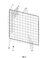
- FIG. 2 the fiber furnace 2 is shown with the inventively provided arrangement of the heating bushes 15.
- the heating bushes 15 are arranged in a plane in the form of a matrix 22.
- the matrix 22 has matrix axes 23, 24 which are arranged at an angle to one another and at whose crossing points the heating bushes 15 are arranged. In each direction of the matrix axes 23, 24, the adjacent Schubuchsen 15 are arranged at the same distance from each other.
- the matrix axes 23, 24 are arranged at a predetermined angle ⁇ to each other.
- the angle ⁇ is chosen according to the invention smaller than 90 °.
- the fiber furnace 2 has a matrix structure of 10 ⁇ 11 with a total of 110 heating bushes 15.
- a sizing roll 20.1, 20.2 out half of the drawn from the preforms 11 glass fibers 5 via a in the FIG. 2 not shown sizing roll 20.1, 20.2 out.
- the sizing rolls 20.1, 20.2 are arranged at a predetermined angle to the corresponding matrix main axis in order to ensure an optimal spacing of the glass fibers 5 on the sizing roll 20.1, 20.2.
- FIG. 3 a Bankbuchse 15 is shown in cross section to the longitudinal axis A.
- the Schubuchse 15 has at the upper end 25 an inner and outer flow orifices 26.1, 26.2, with which within the Schubuchse 15 a laminar flow of air during the melting process can be produced.
- the Schubuchse 15 further includes heating elements 27, which are electrically operated.
- the heating elements 27 are arranged as heating coils around the bushing 28, through which the in the FIG. 3 not shown preform 11 is feasible.
- a quartz tube designed as a diffuser 29 the heating coil 27 is covered with respect to the preform 11.
- an extension 31 is arranged, which acts as a flow collar. With the extension 31, it is possible to achieve a predetermined temperature profile for the cooling process of the glass fibers 5 after melting.
- the extension 31 can be made in one piece with the quartz glass. As appropriate, it has also proved a separate copper bushing as an extension 31.
- FIG. 4 the Schubuchse 15 is shown with an inserted preform 11.
- the preform 11 has a jacket tube 32 and a core rod 33.
- the preform 11 is inserted at the upper end 25 in the Schubuchse 15.
- the resulting between the outer flow aperture 26.2 and the preform 11 annular gap 34 is variable, for example, by the inner flow aperture 26.1 is removed. This ensures that the annular gap is larger. As a result, more air is carried past the preform 11 and thus a larger amount of heat is removed from the heating bush 15, which is then no longer available to the melting process.
- the cooling elements can be embedded in metal, preferably copper, in the material carrying the heating coils 27.
- the cooling elements are otherwise in the FIG. 4 not shown.
- the glass is pulled in the form of a fiber cladding and a fiber core having glass fiber 5 and passed through the extension 31, where the glass fiber 5 is already cooled in a predetermined manner.
- a targeted temperature profile can be set for the cooling process.
- special measures for the ventilation of the extension 31 or by an arrangement or geometry of the extension 31 to set a predetermined temperature profile for the cooling process of the glass fiber 5. In this case, it is advantageously achieved that a certain air flow is generated at the glass fiber 5 by the extension 31.
Landscapes
- Chemical & Material Sciences (AREA)
- Engineering & Computer Science (AREA)
- Materials Engineering (AREA)
- Geochemistry & Mineralogy (AREA)
- Manufacturing & Machinery (AREA)
- General Life Sciences & Earth Sciences (AREA)
- Life Sciences & Earth Sciences (AREA)
- Organic Chemistry (AREA)
- Physics & Mathematics (AREA)
- Thermal Sciences (AREA)
- Manufacture, Treatment Of Glass Fibers (AREA)
- Reinforced Plastic Materials (AREA)
- Surface Treatment Of Glass Fibres Or Filaments (AREA)
Applications Claiming Priority (2)
| Application Number | Priority Date | Filing Date | Title |
|---|---|---|---|
| DE10344205A DE10344205B4 (de) | 2003-09-22 | 2003-09-22 | Vorrichtung und Verfahren zum Herstellen von Glasfasern |
| DE10344205 | 2003-09-22 |
Publications (2)
| Publication Number | Publication Date |
|---|---|
| EP1516860A1 EP1516860A1 (de) | 2005-03-23 |
| EP1516860B1 true EP1516860B1 (de) | 2019-11-06 |
Family
ID=34177919
Family Applications (1)
| Application Number | Title | Priority Date | Filing Date |
|---|---|---|---|
| EP04022368.7A Expired - Lifetime EP1516860B1 (de) | 2003-09-22 | 2004-09-20 | Vorrichtung und Verfahren zum Herstellen von Glasfasern |
Country Status (5)
| Country | Link |
|---|---|
| EP (1) | EP1516860B1 (https=) |
| JP (1) | JP2005162598A (https=) |
| CN (2) | CN1298648C (https=) |
| CA (1) | CA2482105A1 (https=) |
| DE (1) | DE10344205B4 (https=) |
Families Citing this family (14)
| Publication number | Priority date | Publication date | Assignee | Title |
|---|---|---|---|---|
| FR2922884B1 (fr) * | 2007-10-29 | 2011-11-25 | Saint Gobain Technical Fabrics | Blocs de reception d'une matiere fondue, notamment du verre, et installation de fibrage pourvue de tels blocs |
| EP2243048B1 (de) | 2008-02-14 | 2019-04-24 | Schott AG | Seitenemittierende stufenindexfaser, methode der herstellung, und verwendung selbiger |
| DE102008009137B4 (de) | 2008-02-14 | 2017-09-21 | Schott Ag | Seitenemittierende Stufenindexfaser |
| DE102008009139B4 (de) | 2008-02-14 | 2021-09-23 | Schott Ag | Seitenemittierende Stufenindexfaser, Faserbündel und Flächengebilde und deren Verwendungen sowie Preformen und Verfahren zu deren Herstellung |
| DE102008009138A1 (de) | 2008-02-14 | 2009-08-27 | Schott Ag | Seitenemittierende brechwertangepasste Faser |
| DE102008034791B4 (de) | 2008-07-25 | 2022-01-20 | Schott Ag | Preformen und Verfahren zur Herstellung von seitenemittierenden Stufenindexfasern |
| CN105985014B (zh) * | 2015-02-28 | 2018-11-23 | 武汉长盈通光电技术有限公司 | 一种菱形包层保偏光纤及其制造方法 |
| CN105985015B (zh) * | 2015-02-28 | 2018-10-23 | 武汉长盈通光电技术有限公司 | 一种椭圆芯保偏光纤及其制造方法 |
| WO2018112386A1 (en) | 2016-12-16 | 2018-06-21 | Schott Corporation | Chalcogenide compositions for optical fibers and other systems |
| CN108423982B (zh) * | 2018-05-25 | 2023-05-30 | 泰安佳成机电科技有限公司 | 玻璃纤维拉丝机的强制分束行程控制装置 |
| CN108929032B (zh) * | 2018-07-26 | 2021-08-31 | 杭州富通通信技术股份有限公司 | 光纤加工方法 |
| CN114426403A (zh) * | 2022-01-20 | 2022-05-03 | 四川航天拓鑫玄武岩实业有限公司 | 一种用于调节纤维直径均匀性的涂油装置 |
| CN117620477A (zh) * | 2023-11-24 | 2024-03-01 | 新代科技(苏州)有限公司 | 一种基于激光矩形管材切割随管件外型浮动支撑的方法 |
| CN118993525B (zh) * | 2024-10-22 | 2024-12-20 | 江苏欧威环保科技发展有限公司 | 一种玻璃纤维用输送装置 |
Family Cites Families (5)
| Publication number | Priority date | Publication date | Assignee | Title |
|---|---|---|---|---|
| US3193363A (en) * | 1960-01-15 | 1965-07-06 | American Optical Corp | Light-conducting devices and apparatus for making the same |
| FR2452470B1 (https=) * | 1979-03-29 | 1984-06-29 | Gouronnec Alain | |
| KR100334779B1 (ko) * | 1999-08-25 | 2002-05-02 | 윤종용 | 광섬유 다중 인출 설비 |
| WO2002102578A1 (en) * | 2000-11-16 | 2002-12-27 | Schott Glas | Method of forming an ordered array of fibers |
| US6620350B2 (en) * | 2001-10-01 | 2003-09-16 | Hon Hai Precision Ind. Co., Ltd. | Method for making gradient refractive index optical components |
-
2003
- 2003-09-22 DE DE10344205A patent/DE10344205B4/de not_active Expired - Lifetime
-
2004
- 2004-09-20 EP EP04022368.7A patent/EP1516860B1/de not_active Expired - Lifetime
- 2004-09-21 CA CA002482105A patent/CA2482105A1/en not_active Abandoned
- 2004-09-22 CN CNB2004100959683A patent/CN1298648C/zh not_active Expired - Fee Related
- 2004-09-22 CN CNA2006101416359A patent/CN1927749A/zh active Pending
- 2004-09-22 JP JP2004275761A patent/JP2005162598A/ja not_active Withdrawn
Non-Patent Citations (1)
| Title |
|---|
| None * |
Also Published As
| Publication number | Publication date |
|---|---|
| CN1603262A (zh) | 2005-04-06 |
| CN1927749A (zh) | 2007-03-14 |
| JP2005162598A (ja) | 2005-06-23 |
| EP1516860A1 (de) | 2005-03-23 |
| DE10344205A1 (de) | 2005-05-12 |
| CA2482105A1 (en) | 2005-03-22 |
| CN1298648C (zh) | 2007-02-07 |
| DE10344205B4 (de) | 2005-09-08 |
Similar Documents
| Publication | Publication Date | Title |
|---|---|---|
| EP1516860B1 (de) | Vorrichtung und Verfahren zum Herstellen von Glasfasern | |
| DE69620468T2 (de) | Methode und apparat zum beschichten optischer fasern | |
| DE2818575C3 (de) | Verfahren und Vorrichtung zur Herstellung von Kabelelementen mit optischen Fasern | |
| EP0767148B1 (de) | Verfahren und Vorrichtung zum Herstellen eines Bauteils aus Glas durch Ziehen aus einem Rohling | |
| DE69421594T2 (de) | Ziehofen für optische fasern und ziehverfahren | |
| DE10019660B4 (de) | Verfahren zum Verspinnen einer Spinnlösung und Spinnkopf | |
| EP0887319B1 (de) | Vorrichtung und Verfahren zur Regelung der Beschichtungsdicke einer optischen Faser | |
| EP0703478B1 (de) | Verfahren zur Herstellung eines optischen Kabels aus einem Metallrohr | |
| DE2621508C2 (de) | Verfahren und Vorrichtung zum Herstellen von ummantelten optischen Fasern | |
| DE10128636C1 (de) | Verfahren zur selektiven Beeinflussung der Glasdicke bei der Herstellung von Flachglas und Vorrichtung zur Durchführung des Verfahrens | |
| DE1186976B (de) | Verfahren und Vorrichtung zur Herstellung von Faeden aus Glas oder anderem, in der Waerme erweichendem Material | |
| WO2005035453A1 (de) | Vorrichtung und verfahren zum herstellen von rohren oder stäben | |
| DE1421700C2 (de) | Verfahren zum Herstellen von lichtleitenden Fasern | |
| EP1516861B1 (de) | Vorrichtung und Verfahren zum Konfektionieren optischer Fasern | |
| DE2735186A1 (de) | Verfahren und vorrichtung zur bildung von glasfasern durch ziehen | |
| EP0275994A2 (de) | Verfahren und Vorrichtung zur Herstellung von definierten Lichtwellenleiterlängen in Lichtleitadern | |
| DE19825423A1 (de) | Vorrichtung zur Herstellung eines optischen Kabels | |
| DE10048815C1 (de) | Vorrichtung zur Herstellung eines Glasstranges | |
| DE20320801U1 (de) | Heizbuchse zur Verwendung in einem Faserofen | |
| DE3707969A1 (de) | Vefahren zum herstellen einer optischen faser | |
| US20050066689A1 (en) | Device and method for producing glass fibers | |
| DE2732012C2 (de) | Verfahren zur Herstellung von Glasfasern | |
| DE3035070A1 (de) | Verfahren zum herstellen eines glasfaser-lichtwellenleiters mit verschiedenen durchmessern und verfahren zur herstellung eines verteilerelements oder mischers fuer optische kommunikationssysteme | |
| EP1283194B1 (de) | Vorrichtung zum Herstellen eines Glasrohres oder eines Glasstabes mittels einer Ziehpfeife | |
| DE1042188B (de) | Verfahren und Vorrichtung zum Kraeuseln von Mineral- oder aehnlichen Faeden |
Legal Events
| Date | Code | Title | Description |
|---|---|---|---|
| PUAI | Public reference made under article 153(3) epc to a published international application that has entered the european phase |
Free format text: ORIGINAL CODE: 0009012 |
|
| AK | Designated contracting states |
Kind code of ref document: A1 Designated state(s): AT BE BG CH CY CZ DE DK EE ES FI FR GB GR HU IE IT LI LU MC NL PL PT RO SE SI SK TR |
|
| AX | Request for extension of the european patent |
Extension state: AL HR LT LV MK |
|
| RIN1 | Information on inventor provided before grant (corrected) |
Inventor name: WILLMES, LOTHAR Inventor name: EIS, WOLFGANG |
|
| 17P | Request for examination filed |
Effective date: 20050608 |
|
| AKX | Designation fees paid |
Designated state(s): AT BE BG CH CY CZ DE DK EE ES FI FR GB GR HU IE IT LI LU MC NL PL PT RO SE SI SK TR |
|
| 17Q | First examination report despatched |
Effective date: 20070412 |
|
| STAA | Information on the status of an ep patent application or granted ep patent |
Free format text: STATUS: EXAMINATION IS IN PROGRESS |
|
| GRAP | Despatch of communication of intention to grant a patent |
Free format text: ORIGINAL CODE: EPIDOSNIGR1 |
|
| STAA | Information on the status of an ep patent application or granted ep patent |
Free format text: STATUS: GRANT OF PATENT IS INTENDED |
|
| INTG | Intention to grant announced |
Effective date: 20190614 |
|
| GRAS | Grant fee paid |
Free format text: ORIGINAL CODE: EPIDOSNIGR3 |
|
| GRAA | (expected) grant |
Free format text: ORIGINAL CODE: 0009210 |
|
| STAA | Information on the status of an ep patent application or granted ep patent |
Free format text: STATUS: THE PATENT HAS BEEN GRANTED |
|
| AK | Designated contracting states |
Kind code of ref document: B1 Designated state(s): AT BE BG CH CY CZ DE DK EE ES FI FR GB GR HU IE IT LI LU MC NL PL PT RO SE SI SK TR |
|
| REG | Reference to a national code |
Ref country code: GB Ref legal event code: FG4D Free format text: NOT ENGLISH |
|
| REG | Reference to a national code |
Ref country code: AT Ref legal event code: REF Ref document number: 1198527 Country of ref document: AT Kind code of ref document: T Effective date: 20191115 Ref country code: CH Ref legal event code: EP |
|
| REG | Reference to a national code |
Ref country code: IE Ref legal event code: FG4D Free format text: LANGUAGE OF EP DOCUMENT: GERMAN |
|
| REG | Reference to a national code |
Ref country code: DE Ref legal event code: R096 Ref document number: 502004015838 Country of ref document: DE |
|
| REG | Reference to a national code |
Ref country code: NL Ref legal event code: MP Effective date: 20191106 |
|
| PG25 | Lapsed in a contracting state [announced via postgrant information from national office to epo] |
Ref country code: FI Free format text: LAPSE BECAUSE OF FAILURE TO SUBMIT A TRANSLATION OF THE DESCRIPTION OR TO PAY THE FEE WITHIN THE PRESCRIBED TIME-LIMIT Effective date: 20191106 Ref country code: NL Free format text: LAPSE BECAUSE OF FAILURE TO SUBMIT A TRANSLATION OF THE DESCRIPTION OR TO PAY THE FEE WITHIN THE PRESCRIBED TIME-LIMIT Effective date: 20191106 Ref country code: BG Free format text: LAPSE BECAUSE OF FAILURE TO SUBMIT A TRANSLATION OF THE DESCRIPTION OR TO PAY THE FEE WITHIN THE PRESCRIBED TIME-LIMIT Effective date: 20200206 Ref country code: PL Free format text: LAPSE BECAUSE OF FAILURE TO SUBMIT A TRANSLATION OF THE DESCRIPTION OR TO PAY THE FEE WITHIN THE PRESCRIBED TIME-LIMIT Effective date: 20191106 Ref country code: GR Free format text: LAPSE BECAUSE OF FAILURE TO SUBMIT A TRANSLATION OF THE DESCRIPTION OR TO PAY THE FEE WITHIN THE PRESCRIBED TIME-LIMIT Effective date: 20200207 Ref country code: PT Free format text: LAPSE BECAUSE OF FAILURE TO SUBMIT A TRANSLATION OF THE DESCRIPTION OR TO PAY THE FEE WITHIN THE PRESCRIBED TIME-LIMIT Effective date: 20200306 Ref country code: SE Free format text: LAPSE BECAUSE OF FAILURE TO SUBMIT A TRANSLATION OF THE DESCRIPTION OR TO PAY THE FEE WITHIN THE PRESCRIBED TIME-LIMIT Effective date: 20191106 Ref country code: ES Free format text: LAPSE BECAUSE OF FAILURE TO SUBMIT A TRANSLATION OF THE DESCRIPTION OR TO PAY THE FEE WITHIN THE PRESCRIBED TIME-LIMIT Effective date: 20191106 |
|
| PG25 | Lapsed in a contracting state [announced via postgrant information from national office to epo] |
Ref country code: CZ Free format text: LAPSE BECAUSE OF FAILURE TO SUBMIT A TRANSLATION OF THE DESCRIPTION OR TO PAY THE FEE WITHIN THE PRESCRIBED TIME-LIMIT Effective date: 20191106 Ref country code: EE Free format text: LAPSE BECAUSE OF FAILURE TO SUBMIT A TRANSLATION OF THE DESCRIPTION OR TO PAY THE FEE WITHIN THE PRESCRIBED TIME-LIMIT Effective date: 20191106 Ref country code: DK Free format text: LAPSE BECAUSE OF FAILURE TO SUBMIT A TRANSLATION OF THE DESCRIPTION OR TO PAY THE FEE WITHIN THE PRESCRIBED TIME-LIMIT Effective date: 20191106 Ref country code: RO Free format text: LAPSE BECAUSE OF FAILURE TO SUBMIT A TRANSLATION OF THE DESCRIPTION OR TO PAY THE FEE WITHIN THE PRESCRIBED TIME-LIMIT Effective date: 20191106 |
|
| REG | Reference to a national code |
Ref country code: DE Ref legal event code: R097 Ref document number: 502004015838 Country of ref document: DE |
|
| PG25 | Lapsed in a contracting state [announced via postgrant information from national office to epo] |
Ref country code: SK Free format text: LAPSE BECAUSE OF FAILURE TO SUBMIT A TRANSLATION OF THE DESCRIPTION OR TO PAY THE FEE WITHIN THE PRESCRIBED TIME-LIMIT Effective date: 20191106 |
|
| PLBE | No opposition filed within time limit |
Free format text: ORIGINAL CODE: 0009261 |
|
| STAA | Information on the status of an ep patent application or granted ep patent |
Free format text: STATUS: NO OPPOSITION FILED WITHIN TIME LIMIT |
|
| 26N | No opposition filed |
Effective date: 20200807 |
|
| PG25 | Lapsed in a contracting state [announced via postgrant information from national office to epo] |
Ref country code: SI Free format text: LAPSE BECAUSE OF FAILURE TO SUBMIT A TRANSLATION OF THE DESCRIPTION OR TO PAY THE FEE WITHIN THE PRESCRIBED TIME-LIMIT Effective date: 20191106 |
|
| PG25 | Lapsed in a contracting state [announced via postgrant information from national office to epo] |
Ref country code: IT Free format text: LAPSE BECAUSE OF FAILURE TO SUBMIT A TRANSLATION OF THE DESCRIPTION OR TO PAY THE FEE WITHIN THE PRESCRIBED TIME-LIMIT Effective date: 20191106 |
|
| REG | Reference to a national code |
Ref country code: DE Ref legal event code: R119 Ref document number: 502004015838 Country of ref document: DE |
|
| PG25 | Lapsed in a contracting state [announced via postgrant information from national office to epo] |
Ref country code: MC Free format text: LAPSE BECAUSE OF FAILURE TO SUBMIT A TRANSLATION OF THE DESCRIPTION OR TO PAY THE FEE WITHIN THE PRESCRIBED TIME-LIMIT Effective date: 20191106 |
|
| REG | Reference to a national code |
Ref country code: CH Ref legal event code: PL |
|
| REG | Reference to a national code |
Ref country code: BE Ref legal event code: MM Effective date: 20200930 |
|
| PG25 | Lapsed in a contracting state [announced via postgrant information from national office to epo] |
Ref country code: LU Free format text: LAPSE BECAUSE OF NON-PAYMENT OF DUE FEES Effective date: 20200920 |
|
| PG25 | Lapsed in a contracting state [announced via postgrant information from national office to epo] |
Ref country code: DE Free format text: LAPSE BECAUSE OF NON-PAYMENT OF DUE FEES Effective date: 20210401 |
|
| PG25 | Lapsed in a contracting state [announced via postgrant information from national office to epo] |
Ref country code: CH Free format text: LAPSE BECAUSE OF NON-PAYMENT OF DUE FEES Effective date: 20200930 Ref country code: BE Free format text: LAPSE BECAUSE OF NON-PAYMENT OF DUE FEES Effective date: 20200930 Ref country code: LI Free format text: LAPSE BECAUSE OF NON-PAYMENT OF DUE FEES Effective date: 20200930 Ref country code: IE Free format text: LAPSE BECAUSE OF NON-PAYMENT OF DUE FEES Effective date: 20200920 |
|
| PGFP | Annual fee paid to national office [announced via postgrant information from national office to epo] |
Ref country code: FR Payment date: 20210921 Year of fee payment: 18 |
|
| REG | Reference to a national code |
Ref country code: AT Ref legal event code: MM01 Ref document number: 1198527 Country of ref document: AT Kind code of ref document: T Effective date: 20200920 |
|
| PGFP | Annual fee paid to national office [announced via postgrant information from national office to epo] |
Ref country code: GB Payment date: 20210920 Year of fee payment: 18 |
|
| PG25 | Lapsed in a contracting state [announced via postgrant information from national office to epo] |
Ref country code: AT Free format text: LAPSE BECAUSE OF NON-PAYMENT OF DUE FEES Effective date: 20200920 |
|
| PG25 | Lapsed in a contracting state [announced via postgrant information from national office to epo] |
Ref country code: TR Free format text: LAPSE BECAUSE OF FAILURE TO SUBMIT A TRANSLATION OF THE DESCRIPTION OR TO PAY THE FEE WITHIN THE PRESCRIBED TIME-LIMIT Effective date: 20191106 Ref country code: CY Free format text: LAPSE BECAUSE OF FAILURE TO SUBMIT A TRANSLATION OF THE DESCRIPTION OR TO PAY THE FEE WITHIN THE PRESCRIBED TIME-LIMIT Effective date: 20191106 |
|
| GBPC | Gb: european patent ceased through non-payment of renewal fee |
Effective date: 20220920 |
|
| PG25 | Lapsed in a contracting state [announced via postgrant information from national office to epo] |
Ref country code: FR Free format text: LAPSE BECAUSE OF NON-PAYMENT OF DUE FEES Effective date: 20220930 |
|
| PG25 | Lapsed in a contracting state [announced via postgrant information from national office to epo] |
Ref country code: GB Free format text: LAPSE BECAUSE OF NON-PAYMENT OF DUE FEES Effective date: 20220920 |