EP1516860B1 - Apparatus and method for the production of glass fibres - Google Patents
Apparatus and method for the production of glass fibres Download PDFInfo
- Publication number
- EP1516860B1 EP1516860B1 EP04022368.7A EP04022368A EP1516860B1 EP 1516860 B1 EP1516860 B1 EP 1516860B1 EP 04022368 A EP04022368 A EP 04022368A EP 1516860 B1 EP1516860 B1 EP 1516860B1
- Authority
- EP
- European Patent Office
- Prior art keywords
- heating
- glass fibers
- bushes
- preforms
- fiber
- Prior art date
- Legal status (The legal status is an assumption and is not a legal conclusion. Google has not performed a legal analysis and makes no representation as to the accuracy of the status listed.)
- Active
Links
Images


Classifications
-
- C—CHEMISTRY; METALLURGY
- C03—GLASS; MINERAL OR SLAG WOOL
- C03B—MANUFACTURE, SHAPING, OR SUPPLEMENTARY PROCESSES
- C03B37/00—Manufacture or treatment of flakes, fibres, or filaments from softened glass, minerals, or slags
- C03B37/01—Manufacture of glass fibres or filaments
- C03B37/02—Manufacture of glass fibres or filaments by drawing or extruding, e.g. direct drawing of molten glass from nozzles; Cooling fins therefor
- C03B37/025—Manufacture of glass fibres or filaments by drawing or extruding, e.g. direct drawing of molten glass from nozzles; Cooling fins therefor from reheated softened tubes, rods, fibres or filaments, e.g. drawing fibres from preforms
- C03B37/027—Fibres composed of different sorts of glass, e.g. glass optical fibres
- C03B37/02718—Thermal treatment of the fibre during the drawing process, e.g. cooling
-
- C—CHEMISTRY; METALLURGY
- C03—GLASS; MINERAL OR SLAG WOOL
- C03B—MANUFACTURE, SHAPING, OR SUPPLEMENTARY PROCESSES
- C03B37/00—Manufacture or treatment of flakes, fibres, or filaments from softened glass, minerals, or slags
- C03B37/01—Manufacture of glass fibres or filaments
- C03B37/02—Manufacture of glass fibres or filaments by drawing or extruding, e.g. direct drawing of molten glass from nozzles; Cooling fins therefor
- C03B37/025—Manufacture of glass fibres or filaments by drawing or extruding, e.g. direct drawing of molten glass from nozzles; Cooling fins therefor from reheated softened tubes, rods, fibres or filaments, e.g. drawing fibres from preforms
- C03B37/027—Fibres composed of different sorts of glass, e.g. glass optical fibres
- C03B37/02736—Means for supporting, rotating or feeding the tubes, rods, fibres or filaments to be drawn, e.g. fibre draw towers, preform alignment, butt-joining preforms or dummy parts during feeding
-
- C—CHEMISTRY; METALLURGY
- C03—GLASS; MINERAL OR SLAG WOOL
- C03B—MANUFACTURE, SHAPING, OR SUPPLEMENTARY PROCESSES
- C03B37/00—Manufacture or treatment of flakes, fibres, or filaments from softened glass, minerals, or slags
- C03B37/01—Manufacture of glass fibres or filaments
- C03B37/02—Manufacture of glass fibres or filaments by drawing or extruding, e.g. direct drawing of molten glass from nozzles; Cooling fins therefor
- C03B37/025—Manufacture of glass fibres or filaments by drawing or extruding, e.g. direct drawing of molten glass from nozzles; Cooling fins therefor from reheated softened tubes, rods, fibres or filaments, e.g. drawing fibres from preforms
- C03B37/029—Furnaces therefor
-
- C—CHEMISTRY; METALLURGY
- C03—GLASS; MINERAL OR SLAG WOOL
- C03B—MANUFACTURE, SHAPING, OR SUPPLEMENTARY PROCESSES
- C03B37/00—Manufacture or treatment of flakes, fibres, or filaments from softened glass, minerals, or slags
- C03B37/01—Manufacture of glass fibres or filaments
- C03B37/02—Manufacture of glass fibres or filaments by drawing or extruding, e.g. direct drawing of molten glass from nozzles; Cooling fins therefor
- C03B37/03—Drawing means, e.g. drawing drums ; Traction or tensioning devices
- C03B37/032—Drawing means, e.g. drawing drums ; Traction or tensioning devices for glass optical fibres
-
- C—CHEMISTRY; METALLURGY
- C03—GLASS; MINERAL OR SLAG WOOL
- C03B—MANUFACTURE, SHAPING, OR SUPPLEMENTARY PROCESSES
- C03B2205/00—Fibre drawing or extruding details
- C03B2205/08—Sub-atmospheric pressure applied, e.g. vacuum
-
- C—CHEMISTRY; METALLURGY
- C03—GLASS; MINERAL OR SLAG WOOL
- C03B—MANUFACTURE, SHAPING, OR SUPPLEMENTARY PROCESSES
- C03B2205/00—Fibre drawing or extruding details
- C03B2205/32—Simultaneous drawing of multiple preforms to separate multiple fibres
-
- C—CHEMISTRY; METALLURGY
- C03—GLASS; MINERAL OR SLAG WOOL
- C03B—MANUFACTURE, SHAPING, OR SUPPLEMENTARY PROCESSES
- C03B2205/00—Fibre drawing or extruding details
- C03B2205/60—Optical fibre draw furnaces
- C03B2205/70—Draw furnace insulation
-
- C—CHEMISTRY; METALLURGY
- C03—GLASS; MINERAL OR SLAG WOOL
- C03B—MANUFACTURE, SHAPING, OR SUPPLEMENTARY PROCESSES
- C03B2205/00—Fibre drawing or extruding details
- C03B2205/60—Optical fibre draw furnaces
- C03B2205/72—Controlling or measuring the draw furnace temperature
Definitions
- the invention relates to a device for producing optical glass fibers from preforms, in particular multicomponent glass fibers, with a Schubuchsen having fiber furnace, with a tracking device for holding and tracking the preforms in the Schubuchsen and a drawing and Beschlagungsstrom for continuing the glass fibers to a confectioning.
- the invention comprises a method for producing glass fibers from preforms, the preforms being introduced with a tracking device into the heating bushes of the fiber furnace and the glass fibers drawn from the heating bushes cooled via a downstream cooling section and passed on via a drawing system to a packaging device become.
- Preforms consist at least of a rod of a specific glass material with a predetermined diameter.
- the glass fibers have a certain quality in terms of the diameter of each glass fiber or the diameter variance of several simultaneously produced glass fibers, with an optimal reflectivity for the guided light through the optical fiber is necessary.
- These properties are achieved in multicomponent glass fibers by multilayer preforms comprising a core rod and, for example, a cladding tube.
- the glass fibers drawn therefrom have a core and an associated jacket.
- the high reflection properties are generated by the jacket, which has a certain refractive index.
- the core rod is made of a material with a higher refractive index than that of the cladding material to ensure the light-guiding and optical properties.
- the cladding material is drawn over the core material and the two materials combine.
- the diameters of the glass fibers be kept constant.
- the temperature profiles in the fiber furnace are of crucial importance for the optical and mechanical properties of the resulting glass fibers.
- the prior art discloses a device which comprises a melting, drawing and packaging device.
- the smelting plant has a fiber furnace.
- the fiber furnace has openings into which preforms can be inserted.
- the device according to the prior art further comprises a tracking device, for holding and tracking the preforms and a drawing system for further routing of the glass fibers and a confectioning device.
- Preforms are introduced into the fiber furnace, whereby the fiber furnace is heated centrally.
- the arrangement of a number of N openings is axially symmetrical to a central axis or linear.
- the fiber bundles are brought out tangentially to the pulling device.
- this requires further deflection means, which have to generate a deflection of individual glass fibers so that the originally cylindrically arranged fibers can be converted into a band.
- Such deflecting lead to unfavorable transport of the fibers, whereby the merging is made difficult to a band-shaped fiber bundle, which is a prerequisite for a uniform further processing in a Beschlagungsstrom.
- the object of the invention is therefore to avoid the disadvantages of the prior art and to provide an apparatus and a method for producing optical glass fibers, with which the above-described quality requirements can be met, and with which a sufficient number of glass fibers, preferably of multilayer preforms, can be produced simultaneously.
- the Wienbuchsen in the fiber furnace having a matrix-like arrangement for simultaneously receiving a plurality of preforms that the main axes of the array with a predetermined offset angle ( ⁇ ) are arranged to each other, that the offset angle of the matrix axes ⁇ ⁇ 90 ° and that the from the Schwarzbuchsen drawn glass fibers band-shaped side by side lying on the drawing and Beschlagungsstrom are receivable.
- the arrangement of the heating bushes ensures that the glass fibers can be pulled out of the fiber oven with a small offset distance from each other. It is possible to deflect the glass fibers accordingly on a downstream roller.
- the offset of the glass fibers is achieved in that the matrix main axes are arranged at a predetermined offset angle to each other.
- the Schubuchsen are arranged lozenge-shaped in the fiber oven. It is further provided that the distance between the immediately adjacent Thompsonsen on each matrix axis is the same. Furthermore, it is provided that the Schubuchsen are arranged in a plane.
- a multiplicity of preforms can be guided synchronously through the heating bushes and the glass fibers produced in the fiber furnace can be drawn with a predetermined pulling speed from the preforms located in the heating bushes. It is provided according to the invention that the glass fibers are deflected on at least one downstream deflection roller without touching and crossing. Thus, the glass fibers are drawn in their entirety with the same pulling speed from the Schubuchsen the fiber furnace.
- the fiber furnace has a number of at least 110 heating bushes.
- a favorable arrangement can be achieved in that the matrix structure 10 has heating bushes in the direction of the one main matrix axis and 11 heating bushes in the direction of the other main matrix axis. It has been found that an advantageous utilization of the heating power of all Schubuchsen can be better optimized with a larger number of Schubuchsen. This unwanted temperature fluctuations are already kept structurally low.
- the glass fibers are guided by one half of the fiber furnace on a respective deflection roller and each to a Beschlagungsstrom.
- the fiber oven has a temperature control and that the temperature control includes individual regulations of the Schubuchseninnentemperatur.
- the temperature control includes individual regulations of the Schubuchseninnentemperatur.
- both the total temperature and the temperatures of the individual Schubuchsen can be controlled and regulated by the temperature control. This allows an individual adaptation of the temperature profile to external and internal influencing factors.
- the individual controls have measuring and compensating means for adjusting the temperatures of the heating bushes relative to the adjacent heating bushes.
- sensors are provided within the Schubuchsen, which are connected to the temperature control.
- the temperatures of the individual heating bushes are regulated.
- All heating bushes are heated to a setpoint, which lies in the range between about 800 ° C and 1100 ° C.
- Disturbance variables which cause the heating bushes to have different temperatures from one another and altogether from the setpoint value are compensated by respective offset settings.
- All heating bushes are regulated to the same setpoint within a temperature band of about 1 ° C.
- the temperature difference is recorded at regular intervals for each Schubuchse and deducted the determined value of the offset or attributed to him.
- long-term effects such as aging of the thermocouples and Schubuchsen or other disturbances from outside the heating bushes, also be compensated by the offset setting.
- the compensating means comprise heating and cooling elements, for example electronic components, with which the temperatures in the heating bushes can be increased or decreased as needed.
- each Thompsonbuchse has at least one heating element, preferably a plurality of separately controllable heating coils, and that between the heating element and the preform at least one diffuser for scattering the heating radiation is arranged.
- Advantage of this embodiment is that with several heating coils on the one hand, a precisely calculated temperature profile can be set in the Schubuchse. On the other hand, steep temperature gradients are smoothed by the diffuser.
- the diffuser preferably comprises a quartz tube and that the preform of the tracking device through the quartz glass is feasible.
- each heating bush has fluid for generating a laminar flow of air in the heating bush. This makes it possible to adjust pre-calculated flow conditions in an advantageous manner.
- the fluid comprises a preferably integrally connected to the diffuser arranged in the lower part of the Schubuchse extension, which is free of heating elements. This causes that under the Schubuchse an air buffer can form, which is heated by the heating radiation. The heated air is directed into the heating bush.
- the fluid at least one flow aperture comprise at the upper end of the heating bushes, which ensures an annular gap with a predetermined gap width around the preforms for the air outlet.
- the flow diaphragm makes it possible to influence the laminar velocity of the air flow by fixing the annular gap in the upper region of the heating bush. It is also possible to use a plurality of flow diaphragms with different outside diameters matched to the respective annular gaps to be covered. It can thus be easily adapted to the annular gap to different diameters of preforms or reacted to changes in the flow conditions in a Schubuchse during the drawing process. It is provided with an advantageous embodiment that the Edelbuchsen have the same annular gaps throughout the fiber furnace.
- the tracking device has a support plate with individual suspensions for receiving the individual preforms. This allows each preform to be suspended individually. In the case of a small number of glass fibers to be produced, individual individual suspensions can also remain unpopulated.
- each individual suspension has a vacuum connection for connecting the preform to a central vacuum system.
- the vacuum draws off the air between the materials so that air pockets between the layers can be avoided.
- the invention proposes that the support plate for the advance of the preforms by means of threaded spindle and guide by a gear motor is driven and braked.
- the support disk is manually and / or automatically moved into an operating position, so that the support disk is quickly moved back into its operating position after the drawing process.
- the fiber furnace has a flow collar at the output end of the Schubuchsen, by means of which an air buffer for the delayed cooling of the glass fibers can be generated. It has proven to be advantageous in this case that targeted cooling profiles for the glass fibers can be achieved with this flow collar.
- the fiber furnace downstream of a cooling section for cooling the glass fibers.
- the cooling section has a funnel through which the glass fibers can be guided to the drawing and coating installation.
- the funnel is disposed downstream of the fiber furnace and positioned below the flow collar in the cooling section, so that when setting up the device, the first molten glass drops of the preforms targeted to bamboosplatz on the drawing and Beschlagungsstrom are feasible.
- the glass drops hit when falling down on the funnel and slip with the following fiber through the funnel to the drawing and Beschlagungsstrom, where they can preferably be picked up manually and placed in the Beschlagungsstrom on sizing rollers.
- the glass fibers of each oven half can be guided via a respective sizing roll. This ensures that a large number of glass fibers can be produced and processed simultaneously.
- the glass fibers are guided in each case around the corresponding sizing roll, arranged side by side in strip form and uniformly provided with sizing agent. It is envisaged that the glass fibers will not touch.
- a further advantageous embodiment of the device is achieved in that the sizing rolls are arranged at a predetermined angle to the main matrix axes.
- the device is facilitated at the start of drawing and further ensures that the glass fibers have sufficient distance from each other while they are coated.
- the inventive method is characterized in that the glass fibers are drawn with a predetermined constant diameter from the heating bushes and cooled over the cooling section in a predetermined manner and that by means of arrangement of the heating bushes a contact and crossing free pulling the glass fibers is guaranteed.
- the glass fibers are pulled out of the heating bushes with constant pulling speed.
- the optical requirements on the glass material of the glass fibers and the physical properties of the fiber bundles thus produced are thereby sufficiently ensured that fluctuations in the drawing speed the individual glass fibers are avoided.
- the ratio of the mass of the molten glass material and the mass of the glass material taken off as the glass fiber is kept constant. This is achieved in that each preform is pulled with a controlled temperature profile in the associated Schubuchse and / or feed the support plate.
- the glass fibers drawn from the heating bushes be cooled over a predetermined temperature profile.
- the special geometric arrangement of the heating bushes ensures that the glass fibers can be pulled out of the fiber furnace and passed over the cooling section without being touched or crossed with one another. Furthermore, it is thus possible after the cooling section that the glass fibers are uniformly wetted with sizing agent on the downstream finishing rollers of a Betschungsstrom.
- the drawing of the glass fibers is performed by pulling the glass fibers from a peel roll at the same pulling rate.
- the glass fibers are also on the sizing rolls also touching and crossing on the peel-off. Thereafter, the glass fibers can be bundled and made up, so that fiber bundles or fiber cables can be produced simultaneously with a large number of glass fibers.
- the drawing speed of the peel-off roller and the feed of the carrier disk are controlled by means of an electronic data processing system.
- the temperatures in the heating bushes are regulated by means of the electronic data processing system.
- the invention provides that the glass fibers are assembled without feedback.
- the glass fibers are guided by means of a secondary role around the peel-off roller in order to obtain the largest possible Abziehreibung on the roll surface. From the minor role, the glass fibers are fed to the reaction-free confectioning device, which prevents that during assembly forces are exerted on several or individual glass fibers, which make the constancy of the pulling rate and thus the diameter accuracy in question.
- heating bushes have shown, which have at least one heating element, preferably a plurality of separately controllable heating coils, wherein between the heating element and the preform at least one diffuser for scattering the heating radiation is arranged.
- the diffuser preferably comprises a quartz tube, through which a preform can be guided.
- the fluid may comprise a preferably integrally connected to the diffuser connected in the lower part of the Edelbuchse extension, which is free of heating elements, or at least comprise a flow aperture at the upper end of the Edelbuchsen, which ensures an annular gap with a predetermined gap width around the preforms for the air outlet ,
- FIG. 1 the device 1 according to the invention with the fiber furnace 2 and a drawing and Beschlagungsstrom 3 is shown.
- the drawing and Beschlagungsstrom 3 is downstream of a confectioning 4, which reassembled the produced glass fibers 5 as a fiber bundle 6 on take-up reels 7 without any effect on the reaction.
- the cooling section 8 is interposed, wherein the glass fibers 5 are passed through a funnel 9.
- the cooling section 8 has a fiber collar 2 immediately downstream flow collar 10, which serves that the glass fibers 5 are cooled with a predetermined temperature profile.
- the glass fibers 5 are drawn off from preforms 11, wherein the preforms are introduced by means of a tracking device 12 in the fiber furnace 2.
- the individual preforms 11 are fastened to a carrier disk 13 of the tracking device 12.
- the support plate 13 is in a guide 14 by means of a in the FIG. 1 not shown gear spindle, preferably by means of a ball screw, guided and is driven by a geared motor. In this case, the support plate 13 is driven during normal tracking of the preforms 11 with the provided for pulling feed. If the pulling of the glass fibers 5 is terminated, the support disk 13 can be moved manually or, for example, at the end of the preforms 11, automatically into an operating position in which the Preformreste removed and new preforms 11 can be attached to the support plate 13.
- the fiber furnace 2 has a plurality of Bankbuchsen 15, which in FIG. 3 and 4 be explained in more detail.
- the preforms 11 are introduced by the tracking device 12 in a manner in the Schubuchsen 15 that the glass fibers 5 can be continuously guided over the Bescherungsstrom 16 of the drawing system 17 to the packaging device 4.
- the drawing unit 17 has for this purpose a peel-off roller 18, wherein the glass fibers 5 are guided by a secondary roller 19 adjacent to each other around the peel-off roller 18, so that the glass fibers 5 are pulled by the peel-off roller 18 at the same pulling speed.
- the static friction of the glass fibers 5 can be optimally maintained at the peel-off roller 18 and all glass fibers 5 are drawn from the heating bushes 15 of the fiber furnace 2 at a substantially identical pulling speed.
- An electronic data processing system controls the drawing process in accordance with the feed of the tracking device 12 and the pulling speed.
- the packaging device 4 adjusts itself automatically to the predetermined speed of the peel-off roller 18, with which the fiber bundle 6 can be wound up.
- the glass fibers 5 are pulled through the Bescherungsstrom 16 before the draw-off roller 18.
- the glass fibers 5 are arranged band-like juxtaposed by two sizing rolls 20.1, 20.2 added. It is envisaged that the glass fibers 5 are guided in each case one half of the fiber furnace 2 via one of the sizing rolls 20.1, 20.2.
- the sizing rolls 20.1, 20.2 are partially immersed, ie up to 45% in a reservoir 21.
- the glass fibers 5 are uniformly wetted with sizing agent over the surface of the sizing rolls 20.1, 20.2. Subsequently, the glass fibers 5, also arranged like a strip next to each other, received by the peeling roller 18.
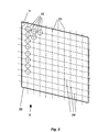
- FIG. 2 the fiber furnace 2 is shown with the inventively provided arrangement of the heating bushes 15.
- the heating bushes 15 are arranged in a plane in the form of a matrix 22.
- the matrix 22 has matrix axes 23, 24 which are arranged at an angle to one another and at whose crossing points the heating bushes 15 are arranged. In each direction of the matrix axes 23, 24, the adjacent Schubuchsen 15 are arranged at the same distance from each other.
- the matrix axes 23, 24 are arranged at a predetermined angle ⁇ to each other.
- the angle ⁇ is chosen according to the invention smaller than 90 °.
- the fiber furnace 2 has a matrix structure of 10 ⁇ 11 with a total of 110 heating bushes 15.
- a sizing roll 20.1, 20.2 out half of the drawn from the preforms 11 glass fibers 5 via a in the FIG. 2 not shown sizing roll 20.1, 20.2 out.
- the sizing rolls 20.1, 20.2 are arranged at a predetermined angle to the corresponding matrix main axis in order to ensure an optimal spacing of the glass fibers 5 on the sizing roll 20.1, 20.2.
- FIG. 3 a Bankbuchse 15 is shown in cross section to the longitudinal axis A.
- the Schubuchse 15 has at the upper end 25 an inner and outer flow orifices 26.1, 26.2, with which within the Schubuchse 15 a laminar flow of air during the melting process can be produced.
- the Schubuchse 15 further includes heating elements 27, which are electrically operated.
- the heating elements 27 are arranged as heating coils around the bushing 28, through which the in the FIG. 3 not shown preform 11 is feasible.
- a quartz tube designed as a diffuser 29 the heating coil 27 is covered with respect to the preform 11.
- an extension 31 is arranged, which acts as a flow collar. With the extension 31, it is possible to achieve a predetermined temperature profile for the cooling process of the glass fibers 5 after melting.
- the extension 31 can be made in one piece with the quartz glass. As appropriate, it has also proved a separate copper bushing as an extension 31.
- FIG. 4 the Schubuchse 15 is shown with an inserted preform 11.
- the preform 11 has a jacket tube 32 and a core rod 33.
- the preform 11 is inserted at the upper end 25 in the Schubuchse 15.
- the resulting between the outer flow aperture 26.2 and the preform 11 annular gap 34 is variable, for example, by the inner flow aperture 26.1 is removed. This ensures that the annular gap is larger. As a result, more air is carried past the preform 11 and thus a larger amount of heat is removed from the heating bush 15, which is then no longer available to the melting process.
- the cooling elements can be embedded in metal, preferably copper, in the material carrying the heating coils 27.
- the cooling elements are otherwise in the FIG. 4 not shown.
- the glass is pulled in the form of a fiber cladding and a fiber core having glass fiber 5 and passed through the extension 31, where the glass fiber 5 is already cooled in a predetermined manner.
- a targeted temperature profile can be set for the cooling process.
- special measures for the ventilation of the extension 31 or by an arrangement or geometry of the extension 31 to set a predetermined temperature profile for the cooling process of the glass fiber 5. In this case, it is advantageously achieved that a certain air flow is generated at the glass fiber 5 by the extension 31.
Description
Die Erfindung betrifft eine Vorrichtung zum Herstellen von optischen Glasfasern aus Preformen, insbesondere von Mehrkomponentenglasfasern, mit einem Heizbuchsen aufweisenden Faserofen, mit einer Nachführvorrichtung zum Halten und Nachführen der Preformen in den Heizbuchsen und einer Zieh- und Beschlichtungsanlage zum Weiterführen der Glasfasern an eine Konfektioniervorrichtung.The invention relates to a device for producing optical glass fibers from preforms, in particular multicomponent glass fibers, with a Heizbuchsen having fiber furnace, with a tracking device for holding and tracking the preforms in the Heizbuchsen and a drawing and Beschlagungsanlage for continuing the glass fibers to a confectioning.
Des Weiteren ist von der Erfindung ein Verfahren zum Herstellen von Glasfasern aus Preformen umfasst, wobei die Preformen mit einer Nachführvorrichtung in die Heizbuchsen des Faserofens eingeführt werden und wobei die aus den Heizbuchsen gezogenen Glasfasern über eine nachgeordnete Kühlstrecke gekühlt und über eine Ziehanlage zu einer Konfektioniervorrichtung weitergeführt werden.Furthermore, the invention comprises a method for producing glass fibers from preforms, the preforms being introduced with a tracking device into the heating bushes of the fiber furnace and the glass fibers drawn from the heating bushes cooled via a downstream cooling section and passed on via a drawing system to a packaging device become.
Vorrichtungen und Verfahren zum Herstellen von Glasfasern dieser Art sind im Stand der Technik bekannt. Dabei werden Preformen in Heizbuchsen eingeführt und geschmolzen. Das Glas fließt von dem Preformen kontinuierlich ab und wird unterhalb des Faserofens aus den Heizbuchsen gezogen.Devices and methods for producing glass fibers of this type are known in the art. Thereby preforms are introduced into heating bushes and melted. The glass flows continuously away from the preform and is pulled out of the heating bushes below the fiber furnace.
Preformen bestehen zumindest aus einem Stab eines bestimmten Glasmaterials mit einem vorbestimmten Durchmesser. Insbesondere für den Einsatz von Mehrkomponentenglasfasern in Glasfaserbündeln ist es jedoch erforderlich, dass die Glasfasern eine bestimmte Qualität hinsichtlich des Durchmessers jeder Glasfaser beziehungsweise der Durchmesservarianz mehrerer gleichzeitig hergestellter Glasfasern aufweisen, wobei eine optimale Reflexionsfähigkeit für das durch die Glasfaser geleitete Licht notwendig ist. Diese Eigenschaften werden bei Mehrkomponentenglasfasern durch mehrschichtige Preformen erzielt, welche einen Kernstab und zum Beispiel ein Mantelrohr umfassen. Die daraus gezogenen Glasfasern weisen einen Kern und einen damit verbundenen Mantel auf. Dabei werden die hohen Reflexionseigenschaften durch den Mantel erzeugt, welcher eine bestimmte Brechungszahl aufweist. Der Kernstab besteht aus einem Material mit einer höheren Brechzahl als die des Mantelmaterials, um die lichtleitenden und optischen Eigenschaften zu gewährleisten.Preforms consist at least of a rod of a specific glass material with a predetermined diameter. In particular, for the use of multi-component glass fibers in glass fiber bundles, however, it is necessary that the glass fibers have a certain quality in terms of the diameter of each glass fiber or the diameter variance of several simultaneously produced glass fibers, with an optimal reflectivity for the guided light through the optical fiber is necessary. These properties are achieved in multicomponent glass fibers by multilayer preforms comprising a core rod and, for example, a cladding tube. The glass fibers drawn therefrom have a core and an associated jacket. The high reflection properties are generated by the jacket, which has a certain refractive index. The core rod is made of a material with a higher refractive index than that of the cladding material to ensure the light-guiding and optical properties.
Beim Schmelzen der Preform wird mit dem Abtropfen des ersten Glastropfens das Mantelmaterial über das Kernmaterial gezogen und die beiden Materialien vereinigen sich.As the preform melts, as the first glass drop drips, the cladding material is drawn over the core material and the two materials combine.
Um die Materialstärken konstant zu halten und optimale optische Eigenschaften der unterschiedlichen Materialien in den Glasfasern zu erzeugen, ist es erforderlich, dass die Durchmesser der Glasfasern konstant gehalten werden. Darüber hinaus sind die Temperaturverläufe im Faserofen von entscheidender Bedeutung für die optischen und mechanischen Eigenschaften der daraus entstehenden Glasfasern.In order to keep the material thicknesses constant and to produce optimal optical properties of the different materials in the glass fibers, it is necessary that the diameters of the glass fibers be kept constant. In addition, the temperature profiles in the fiber furnace are of crucial importance for the optical and mechanical properties of the resulting glass fibers.
Hierzu werden im Stand der Technik Herstellungsweisen unterschieden, welche im Wesentlichen von der Art und Qualität der zu erzeugenden Glasfasern beziehungsweise der Geschwindigkeit der Fasererzeugung und der Anzahl der gleichzeitig herzustellenden Glasfasern abhängen.For this purpose, a distinction is made in the prior art methods of production, which depend essentially on the type and quality of the glass fibers to be produced or the speed of fiber production and the number of simultaneously produced glass fibers.
Aus der
Sie werden wegen der erhöhten Anforderungen an die Durchmessergenauigkeit und wegen der damit notwendig werdenden Prüfmaßnahmen stets einzeln gezogen und nach dem Ziehofen auch einzeln nachverarbeitet. Die Verbesserungen, welche mit der
Diese Herstellungsweise ist für die Erzeugung von Mehrkomponentenglasfasern ungeeignet, da meist eine Vielzahl von Glasfasern in Glasfaserbündeln verwendet werden, welche hinsichtlich der Durchmessergenauigkeit und der Beschichtung andere Anforderungen zu erfüllen haben. Es hat sich erwiesen, dass eine wirtschaftliche Herstellung derartiger Glasfaserbündel mit Einzelfaserziehvorrichtungen, auch wenn sie zu mehreren parallelgeschaltet sind, nicht möglich ist.This method of manufacture is unsuitable for the production of multicomponent glass fibers, since a large number of glass fibers are usually used in glass fiber bundles, which have different requirements with regard to the diameter accuracy and the coating. It has been found that economical production of such fiberglass bundles with single-fiber drawing devices, even if they are connected in parallel to several, is not possible.
Insbesondere hat sich als Nachteil solcher Vorrichtungen erwiesen, dass trotz Parallelschaltung von mehreren Einzelfaserziehanlagen die Anzahl der Glasfasern erheblich unter dem Notwendigen begrenzt bleibt. Zur wirtschaftlichen Herstellung von Glasfaserbündeln sollten eine Vielzahl von Einzelfasern gleichzeitig hergestellt werden können. Auch ist die auf die Einzelfaser bezogene Nachverarbeitung bei der Vorrichtung nach dem Stand der Technik mit erheblichen Kosten verbunden, so dass eine Erzeugung von Faserbündeln für optische Systeme damit unwirtschaftlich wäre.In particular, it has proved to be a disadvantage of such devices that, despite the parallel connection of a plurality of individual fiber drawing systems, the number of glass fibers remains considerably below what is necessary. For the economic production of glass fiber bundles, a large number of individual fibers should be able to be produced simultaneously. Also In the case of the device according to the prior art, the post-processing relating to the single-fiber is associated with considerable costs, so that the production of fiber bundles for optical systems would thus be uneconomical.
Gegenüber den für die Datenübertragung verwendeten Glasfasern kommt es bei Mehrkomponentenglasfasern weniger auf die Qualität der Einzelfasern als auf die des gesamten Faserbündels an. Daneben spielen, anders als bei Datenübertragungsfasern, für die Verwendung von Glasfaserbündel aus Mehrkomponentenglasfasern Wirtschaftlichkeitserwägungen eine wesentlich größere Rolle. Es hat sich gezeigt, dass bei Einzelführung der Glasfasern, wie im vorgenannten Stand der Technik dargestellt, diese Anforderungen nicht gewährleistet werden können.Compared to the glass fibers used for data transmission, the quality of the individual fibers is less important for multicomponent glass fibers than for the entire fiber bundle. In addition, unlike data transmission fibers, economy considerations play a much greater role in the use of glass fiber bundles made of multicomponent glass fibers. It has been shown that with individual guidance of the glass fibers, as shown in the aforementioned prior art, these requirements can not be guaranteed.
In der Druckschrift
Nachteil dieses Standes der Technik ist, dass bei Verwendung von mehr als N=4 Heizbuchsen eine axialsymmetrische Anordnung zu einer kreisförmigen Vorrichtung führt, da die Öffnungen zentral um die Achse verteilt sind. Bei einer linearen Anordnung sind die Öffnungen gerade nebeneinander (d.h. auf einer Geraden) angeordnet. Beides ist nachteilig, da diese Anordnungen zu erheblichen Platzbedarf führen. Außerdem zeigt der Stand der Technik einen zentralen Heizofen auf, der in beiden gezeigten Anordnungen einen Temperaturgradienten aufweist, so dass die Fasern bei größerer Anzahl nicht mit derselben Temperatur gezogen würden, was zu unterschiedlicher Qualität der Fasern führt. Das Ergebnis einer solchen Herstellungsweise sind Faserbündel, welchen homogene Abbildungseigenschaften der Einzelfasern fehlen, so dass es zu unvorhergesehenen Abbildungsfehlern bei der Signalübertragung durch ein solches Faserbündel kommen kann.Disadvantage of this prior art is that when using more than N = 4 Heizbuchsen an axially symmetric arrangement leads to a circular device, since the openings are distributed centrally around the axis. In a linear arrangement, the openings are just next to each other (ie on a straight line). Both are disadvantageous, since these arrangements lead to considerable space requirements. In addition, the prior art shows a central heating furnace which has a temperature gradient in both arrangements shown so that the larger number of fibers would not be drawn at the same temperature, resulting in different quality fibers. The result of such a method of production are fiber bundles, which lack homogeneous imaging properties of the individual fibers, so that unforeseen aberrations in the signal transmission through such a fiber bundle can occur.
Außerdem wird im Stand der Technik offenbart, dass die Faserbündel tangential zur Ziehvorrichtung herausgeführt werden. In Zusammenhang mit der axialsymmetrischen Anordnung mit NxN Öffnungen sind dazu weitere Umlenkmittel nötig, die eine Umlenkung von einzelnen Glasfasern erzeugen müssen, damit die ursprünglich zylindrisch angeordneten Fasern in ein Band überführt werden können. Solche Umlenkmittel führen zu ungünstigem Transport der Fasern, womit das Zusammenführen zu einem bandförmigen Faserbündel erschwert wird, was Voraussetzung für eine gleichmäßige Weiterverarbeitung in einer Beschlichtungsanlage ist.In addition, it is disclosed in the prior art that the fiber bundles are brought out tangentially to the pulling device. In connection with the axisymmetric arrangement with NxN openings, this requires further deflection means, which have to generate a deflection of individual glass fibers so that the originally cylindrically arranged fibers can be converted into a band. Such deflecting lead to unfavorable transport of the fibers, whereby the merging is made difficult to a band-shaped fiber bundle, which is a prerequisite for a uniform further processing in a Beschlagungsanlage.
Aufgabe der Erfindung ist es daher, die Nachteile des Standes der Technik zu vermeiden und eine Vorrichtung sowie ein Verfahren zum Herstellen optischer Glasfasern bereitzustellen, mit welchen die vorbeschriebenen Qualitätsanforderungen erfüllt werden können, und mit denen eine ausreichende Anzahl an Glasfasern, vorzugsweise aus mehrschichtigen Preformen, gleichzeitig herstellbar ist.The object of the invention is therefore to avoid the disadvantages of the prior art and to provide an apparatus and a method for producing optical glass fibers, with which the above-described quality requirements can be met, and with which a sufficient number of glass fibers, preferably of multilayer preforms, can be produced simultaneously.
Eine Lösung der Aufgabe wird durch die Hauptansprüche, erfindungsgemäße Weiterbildungen und Ausgestaltungen der Vorrichtung beziehungsweise des Verfahrens durch die Unteransprüche zur Verfügung gestellt.A solution to the problem is provided by the main claims, developments of the invention and embodiments of the device or the method by the dependent claims.
Es ist dabei erfindungsgemäß vorgesehen, dass die Heizbuchsen im Faserofen eine matrixartige Anordnung zur gleichzeitigen Aufnahme mehrerer Preformen aufweisen, dass die Matrixhauptachsen der Anordnung mit einem vorbestimmten Versatzwinkel (α) zueinander angeordnet sind, dass der Versatzwinkel der Matrixachsen α < 90° ist und dass die aus den Heizbuchsen gezogenen Glasfasern bandförmig nebeneinander liegend von der Zieh- und Beschlichtungsanlage aufnehmbar sind.It is inventively provided that the Heizbuchsen in the fiber furnace having a matrix-like arrangement for simultaneously receiving a plurality of preforms that the main axes of the array with a predetermined offset angle (α) are arranged to each other, that the offset angle of the matrix axes α <90 ° and that the from the Heizbuchsen drawn glass fibers band-shaped side by side lying on the drawing and Beschlagungsanlage are receivable.
Die Anordnung der Heizbuchsen gewährleistet dabei, dass die Glasfasern mit einem kleinen Versatzabstand zueinander aus dem Faserofen gezogen werden können. Dabei ist es möglich, die Glasfasern dementsprechend auf einer nachgeordneten Walze umzulenken.The arrangement of the heating bushes ensures that the glass fibers can be pulled out of the fiber oven with a small offset distance from each other. It is possible to deflect the glass fibers accordingly on a downstream roller.
Der Versatz der Glasfasern wird dadurch erreicht, dass die Matrixhauptachsen mit einem vorbestimmten Versatzwinkel zueinander angeordnet sind. Hierzu ist in vorteilhafter Weise vorgesehen, dass die Heizbuchsen im Faserofen rautenförmig angeordnet sind. Dabei ist weiter vorgesehen, dass der Abstand zwischen den unmittelbar benachbarten Heizbuchsen auf jeder Matrixachse gleich ist. Des Weiteren ist vorgesehen, dass die Heizbuchsen in einer Ebene angeordnet sind.The offset of the glass fibers is achieved in that the matrix main axes are arranged at a predetermined offset angle to each other. For this purpose, it is advantageously provided that the Heizbuchsen are arranged lozenge-shaped in the fiber oven. It is further provided that the distance between the immediately adjacent Heizbuchsen on each matrix axis is the same. Furthermore, it is provided that the Heizbuchsen are arranged in a plane.
Mit der erfindungsgemäßen Vorrichtung können eine Vielzahl von Preformen synchron durch die Heizbuchsen geführt und die im Faserofen hergestellten Glasfasern mit einer vorgegebenen Ziehgeschwindigkeit aus den in den Heizbuchsen befindlichen Preformen gezogen werden. Dabei ist erfindungsgemäß vorgesehen, dass die Glasfasern auf wenigstens einer nachgeordneten Umlenkwalze, ohne sich zu berühren und zu kreuzen, umgelenkt werden. Somit werden die Glasfasern in ihrer Gesamtheit mit gleicher Ziehgeschwindigkeit aus den Heizbuchsen des Faserofens gezogen.With the device according to the invention, a multiplicity of preforms can be guided synchronously through the heating bushes and the glass fibers produced in the fiber furnace can be drawn with a predetermined pulling speed from the preforms located in the heating bushes. It is provided according to the invention that the glass fibers are deflected on at least one downstream deflection roller without touching and crossing. Thus, the glass fibers are drawn in their entirety with the same pulling speed from the Heizbuchsen the fiber furnace.
Dadurch, dass jeder von der Nachführvorrichtung geführten Preform eine Heizbuchse zugeordnet ist, wird ein gleichzeitiges Ziehen von Glasfasern aus allen Preformen ermöglicht.Characterized in that each preform guided by the tracking device is assigned a Heizbuchse, a simultaneous drawing of glass fibers from all preforms is possible.
Eine vorteilhafte Ausgestaltung der Vorrichtung wird erfindungsgemäß dadurch zur Verfügung gestellt, dass der Faserofen eine Anzahl von wenigstens 110 Heizbuchsen aufweist. Dabei ist eine günstige Anordnung dadurch erreichbar, dass die Matrixstruktur 10 Heizbuchsen in Richtung der einen Matrixhauptachse und 11 Heizbuchsen in Richtung der anderen Matrixhauptachse aufweist. Es hat sich nämlich erwiesen, dass eine vorteilhafte Ausnutzung der Heizleistung aller Heizbuchsen mit einer größeren Anzahl an Heizbuchsen besser optimiert werden kann. Dabei werden ungewünschte Temperaturschwankungen bereits konstruktiv gering gehalten. Bei dieser Ausführungsform werden die Glasfasern von jeweils einer Hälfte des Faserofens auf je eine Umlenkrolle und jeweils zu einer Beschlichtungsanlage geführt.An advantageous embodiment of the device according to the invention is provided by the fact that the fiber furnace has a number of at least 110 heating bushes. In this case, a favorable arrangement can be achieved in that the
Um das gewünschte und erforderliche Temperaturprofil zu gewährleisten, ist vorgesehen, dass der Faserofen eine Temperaturregelung aufweist und dass die Temperaturregelung Einzelregelungen der Heizbuchseninnentemperatur umfasst. Somit können über die Temperaturregelung sowohl die Gesamttemperatur als auch die Temperaturen der einzelnen Heizbuchsen kontrolliert und geregelt werden. Dies ermöglicht, eine individuelle Anpassung des Temperaturprofils an äußere und innere Einflussfaktoren.In order to ensure the desired and required temperature profile, it is provided that the fiber oven has a temperature control and that the temperature control includes individual regulations of the Heizbuchseninnentemperatur. Thus, both the total temperature and the temperatures of the individual Heizbuchsen can be controlled and regulated by the temperature control. This allows an individual adaptation of the temperature profile to external and internal influencing factors.
Um die Temperaturen jeweils zu ermitteln und die Temperaturen der einzelnen Heizbuchsen einzeln zu verändern, wird erfindungsgemäß vorgeschlagen, dass die Einzelregelungen Mess- und Ausgleichsmittel zum Abstimmen der Temperaturen der Heizbuchsen relativ zu den benachbarten Heizbuchsen aufweisen. Hierzu sind Sensoren innerhalb der Heizbuchsen vorgesehen, welche mit der Temperaturregelung verbunden sind. Mittels der Sensorwerte werden die Temperaturen der einzelnen Heizbuchsen geregelt. Alle Heizbuchsen werden auf einen Sollwert geheizt, welcher im Bereich zwischen etwa 800°C und 1100°C liegt. Mit der Einzelregelung kann somit in vorteilhafter Weise erreicht werden, dass alle Heizbuchsen individuell auf den Sollwert geregelt werden. Störgrößen, welche bewirken, dass die Heizbuchsen untereinander und insgesamt vom Sollwert abweichende Temperaturen aufweisen, werden durch jeweilige Offseteinstellungen ausgeglichen. Alle Heizbuchsen werden dabei auf den gleichen Sollwert innerhalb eines Temperaturbands von etwa 1°C geregelt. Um Temperaturdifferenzen zwischen den Heizbuchsen untereinander auszugleichen, wird in regelmäßigen Abständen für jede Heizbuchse die Temperaturdifferenz aufgenommen und der ermittelte Wert vom Offset abgezogen oder ihm zugerechnet. Somit können Langzeiteffekte, wie Alterung der Thermoelemente und Heizbuchsen oder sonstige Störgrößen von außerhalb der Heizbuchsen, ebenfalls durch die Offseteinstellung ausgeglichen werden. Die Ausgleichsmittel umfassen Heiz- als auch Kühlelemente, beispielsweise elektronische Bauelemente, mit welchen in den Heizbuchsen je nach Bedarf die Temperaturen erhöht oder gesenkt werden können. In vorteilhafter Weise ist es somit möglich, definierte Zustände der Heizbuchsen und somit des Gesamtsystems des Faserofens einzustellen.In order to determine the temperatures in each case and to change the temperatures of the individual heating bushes individually, it is proposed according to the invention that the individual controls have measuring and compensating means for adjusting the temperatures of the heating bushes relative to the adjacent heating bushes. For this purpose, sensors are provided within the Heizbuchsen, which are connected to the temperature control. By means of the sensor values, the temperatures of the individual heating bushes are regulated. All heating bushes are heated to a setpoint, which lies in the range between about 800 ° C and 1100 ° C. With the individual control can thus be achieved in an advantageous manner be that all heating bushes are individually adjusted to the setpoint. Disturbance variables which cause the heating bushes to have different temperatures from one another and altogether from the setpoint value are compensated by respective offset settings. All heating bushes are regulated to the same setpoint within a temperature band of about 1 ° C. To compensate for temperature differences between the heat sockets with each other, the temperature difference is recorded at regular intervals for each Heizbuchse and deducted the determined value of the offset or attributed to him. Thus, long-term effects, such as aging of the thermocouples and Heizbuchsen or other disturbances from outside the heating bushes, also be compensated by the offset setting. The compensating means comprise heating and cooling elements, for example electronic components, with which the temperatures in the heating bushes can be increased or decreased as needed. Advantageously, it is thus possible to set defined states of the Heizbuchsen and thus the overall system of the fiber furnace.
Des Weiteren wird erfindungsgemäß vorgeschlagen, dass jede Heizbuchse zumindest ein Heizelement, vorzugsweise mehrere gesondert ansteuerbare Heizwendeln, aufweist und dass zwischen dem Heizelement und der Preform zumindest ein Diffusor zum Streuen der Heizstrahlung angeordnet ist. Vorteil dieser Ausführungsform ist es, dass mit mehreren Heizwendeln zum einen ein genau berechnetes Temperaturprofil in der Heizbuchse eingestellt werden kann. Zum anderen werden steile Temperaturgefälle durch den Diffusor geglättet. Dabei ist vorgesehen, dass der Diffusor vorzugsweise ein Quarzrohr umfasst und dass die Preform von der Nachführvorrichtung durch das Quarzglas führbar ist.Furthermore, the invention proposes that each Heizbuchse has at least one heating element, preferably a plurality of separately controllable heating coils, and that between the heating element and the preform at least one diffuser for scattering the heating radiation is arranged. Advantage of this embodiment is that with several heating coils on the one hand, a precisely calculated temperature profile can be set in the Heizbuchse. On the other hand, steep temperature gradients are smoothed by the diffuser. It is provided that the diffuser preferably comprises a quartz tube and that the preform of the tracking device through the quartz glass is feasible.
Innerhalb der Heizbuchse, aber besonders innerhalb des Quarzrohres, können sich ungewünschte Strömungsbedingungen ergeben, welche dazu führen, dass die Preform mit kalter Luft beaufschlagt wird. Um dies zu vermeiden wird erfindungsgemäß vorgeschlagen, dass jede Heizbuchse Strömungsmittel zur Erzeugung einer laminaren Luftströmung in der Heizbuchse aufweist. Hierdurch ist es möglich, in vorteilhafter Weise vorberechnete Strömungsbedingungen einzustellen. Dabei ist vorgesehen, dass die Strömungsmittel eine vorzugsweise einstückig mit dem Diffusor verbundene im unteren Teil der Heizbuchse angeordnete Verlängerung umfassen, welche frei von Heizelementen ist. Dies bewirkt, dass sich unter der Heizbuchse ein Luftpuffer bilden kann, welches durch die Heizstrahlung aufgeheizt wird. Die aufgeheizte Luft wird in die Heizbuchse geleitet. Damit die Strömungsgeschwindigkeit der eingeleiteten Luft nicht ungewünscht dabei zunimmt, ist erfindungsgemäß vorgesehen, dass die Strömungsmittel zumindest eine Strömungsblende am oberen Ende der Heizbuchsen umfassen, welche für den Luftabzug einen Ringspalt mit vorbestimmter Spaltbreite um die Preformen gewährleistet. Durch die Strömungsblende ist es möglich, die Laminargeschwindigkeit der Luftströmung durch Festlegung des Ringspalts im oberen Bereich der Heizbuchse zu beeinflussen. Es ist auch möglich, mehrere Strömungsblenden mit unterschiedlichen, auf die jeweils abzudeckenden Ringspalte abgestimmte Außendurchmesser zu verwenden. Es kann somit in einfacher Weise der Ringspalt an verschiedene Durchmesser von Preformen angepasst oder auf Änderungen der Strömungsbedingungen in einer Heizbuchse während des Ziehprozesses reagiert werden. Dabei ist mit einer vorteilhaften Ausführungsform vorgesehen, dass die Heizbuchsen im gesamten Faserofen die gleichen Ringspalte aufweisen.Within the heating bush, but especially within the quartz tube, undesirable flow conditions may result, which cause the preform to be exposed to cold air. To avoid this, it is proposed according to the invention that each heating bush has fluid for generating a laminar flow of air in the heating bush. This makes it possible to adjust pre-calculated flow conditions in an advantageous manner. It is provided that the fluid comprises a preferably integrally connected to the diffuser arranged in the lower part of the Heizbuchse extension, which is free of heating elements. This causes that under the Heizbuchse an air buffer can form, which is heated by the heating radiation. The heated air is directed into the heating bush. So that the flow velocity of the introduced air does not undesirably increase, it is provided according to the invention that the fluid at least one flow aperture comprise at the upper end of the heating bushes, which ensures an annular gap with a predetermined gap width around the preforms for the air outlet. The flow diaphragm makes it possible to influence the laminar velocity of the air flow by fixing the annular gap in the upper region of the heating bush. It is also possible to use a plurality of flow diaphragms with different outside diameters matched to the respective annular gaps to be covered. It can thus be easily adapted to the annular gap to different diameters of preforms or reacted to changes in the flow conditions in a Heizbuchse during the drawing process. It is provided with an advantageous embodiment that the Heizbuchsen have the same annular gaps throughout the fiber furnace.
Erfindungsgemäß wird weiter vorgeschlagen, dass die Nachführvorrichtung eine Tragscheibe mit Einzelaufhängungen zur Aufnahme der einzelnen Preformen aufweist. Damit kann jede Preform einzeln aufgehängt werden. Bei geringer Anzahl von herzustellenden Glasfasern können dabei einzelne Einzelaufhängungen auch unbestückt bleiben.According to the invention it is further proposed that the tracking device has a support plate with individual suspensions for receiving the individual preforms. This allows each preform to be suspended individually. In the case of a small number of glass fibers to be produced, individual individual suspensions can also remain unpopulated.
Es ist außerdem in vorteilhafter Weise vorgesehen, dass die Einzelaufhängungen an der Tragscheibe eine mit der Heizbuchsenanordnung korrespondierende matrixartige Anordnung aufweisen. Dadurch wird es möglich, dass die Preformen achssymmetrisch zu den Achsen der Heizbuchsen einführbar sind und Abweichungen des Randabstandes der Preformen zu jeweils ihrer Heizbuchse vermieden werden.It is also provided in an advantageous manner that the individual suspensions on the support disc have a corresponding with the Heizbuchsenanordnung matrix-like arrangement. This makes it possible that the preforms are axially symmetrical to the axes of Heizbuchsen inserted and deviations of the edge distance of the preforms are avoided in each case their Heizbuchse.
In vorteilhafter Weise wird das Zusammenschmelzen des Mantel- und Kernmaterials dadurch verbessert, dass jede Einzelaufhängung einen Vakuumanschluss zur Verbindung der Preform an ein zentrales Vakuumsystem aufweist. Das Vakuum zieht dabei die zwischen den Materialien befindliche Luft ab, so dass Lufteinschlüsse zwischen den Schichten vermieden werden können.Advantageously, the melting together of the sheath and core material is improved in that each individual suspension has a vacuum connection for connecting the preform to a central vacuum system. The vacuum draws off the air between the materials so that air pockets between the layers can be avoided.
Um einen synchronen Vorschub aller in der Tragscheibe angeordneten Preformen und damit eine zuverlässige Herstellung von weitgehend identischen Faserdurchmessern zu erreichen, wird erfindungsgemäß vorgeschlagen, dass die Tragscheibe für den Vorschub der Preformen mittels Gewindespindel und Führung von einem Getriebemotor antreibbar und bremsbar ist.In order to achieve a synchronous feed of all arranged in the support plate preforms and thus reliable production of largely identical fiber diameters, the invention proposes that the support plate for the advance of the preforms by means of threaded spindle and guide by a gear motor is driven and braked.
Dabei ist vorgesehen, dass die Tragscheibe manuell und/oder automatisch in eine Bedienposition verfahrbar ist, so dass die Tragscheibe nach dem Ziehvorgang schnell in ihre Bedienposition zurückfahrbar ist.It is provided that the support disk is manually and / or automatically moved into an operating position, so that the support disk is quickly moved back into its operating position after the drawing process.
Es ist des Weiteren erfindungsgemäß vorgesehen, dass der Faserofen einen Strömungskragen am ausgangsseitigen Ende der Heizbuchsen aufweist, mittels dem ein Luftpuffer für die verzögerte Abkühlung der Glasfasern erzeugbar ist. Es hat sich dabei in vorteilhafter Weise erwiesen, dass mit diesem Strömungskragen gezielte Abkühlprofile für die Glasfasern erreichbar sind.It is further provided according to the invention that the fiber furnace has a flow collar at the output end of the Heizbuchsen, by means of which an air buffer for the delayed cooling of the glass fibers can be generated. It has proven to be advantageous in this case that targeted cooling profiles for the glass fibers can be achieved with this flow collar.
Erfindungsgemäß ist vorgesehen, dass dem Faserofen eine Kühlstrecke zum Kühlen der Glasfasern nachgeordnet ist. Als vorteilhaft hat sich dabei erwiesen, dass die Kühlstrecke einen Trichter aufweist, durch den die Glasfasern zur Zieh- und Beschlichtungsanlage führbar sind. Der Trichter ist dem Faserofen nachgeordnet und unterhalb des Strömungskragens in der Kühlstrecke positioniert, so dass beim Einrichten der Vorrichtung, die ersten geschmolzenen Glastropfen der Preformen gezielt zum Einrichtungsplatz an der Zieh- und Beschlichtungsanlage führbar sind. Die Glastropfen treffen beim Herunterfallen auf den Trichter und rutschen mit der nachfolgenden Glasfaser durch den Trichter zur Zieh- und Beschlichtungsanlage, wo sie vorzugsweise manuell aufgenommen und in der Beschlichtungsanlage auf Schlichtewalzen aufgelegt werden können.According to the invention it is provided that the fiber furnace downstream of a cooling section for cooling the glass fibers. It has proven to be advantageous in this case that the cooling section has a funnel through which the glass fibers can be guided to the drawing and coating installation. The funnel is disposed downstream of the fiber furnace and positioned below the flow collar in the cooling section, so that when setting up the device, the first molten glass drops of the preforms targeted to Einrichtungsplatz on the drawing and Beschlagungsanlage are feasible. The glass drops hit when falling down on the funnel and slip with the following fiber through the funnel to the drawing and Beschlagungsanlage, where they can preferably be picked up manually and placed in the Beschlagungsanlage on sizing rollers.
Es hat sich dabei als vorteilhaft erwiesen, dass die Glasfasern jeder Ofenhälfte über je eine Schlichtewalze führbar sind. Somit wird erreicht, dass eine große Anzahl an Glasfasern gleichzeitig hergestellt und weiterverarbeitet werden kann. Die Glasfasern werden dabei jeweils um die entsprechende Schlichtewalze geführt, bandförmig nebeneinander angeordnet und gleichmäßig mit Schlichtemittel versehen. Dabei ist vorgesehen, dass sich die Glasfasern nicht berühren.It has proven to be advantageous that the glass fibers of each oven half can be guided via a respective sizing roll. This ensures that a large number of glass fibers can be produced and processed simultaneously. The glass fibers are guided in each case around the corresponding sizing roll, arranged side by side in strip form and uniformly provided with sizing agent. It is envisaged that the glass fibers will not touch.
Eine weitere vorteilhafte Ausgestaltung der Vorrichtung wird dadurch erreicht, dass die Schlichtewalzen in einem vorbestimmten Winkel zu den Matrixhauptachsen angeordnet sind. Somit wird die Einrichtung der Vorrichtung beim Ziehbeginn erleichtert und weiterhin erreicht, dass die Glasfasern ausreichend Abstand voneinander haben, während sie beschlichtet werden.A further advantageous embodiment of the device is achieved in that the sizing rolls are arranged at a predetermined angle to the main matrix axes. Thus, the device is facilitated at the start of drawing and further ensures that the glass fibers have sufficient distance from each other while they are coated.
Das erfindungsgemäße Verfahren ist dadurch gekennzeichnet, dass die Glasfasern mit einem vorbestimmten gleichbleibenden Durchmesser aus den Heizbuchsen gezogen und über die Kühlstrecke in vorbestimmter Weise gekühlt werden und dass mittels Anordnung der Heizbuchsen ein berührungs- und kreuzungsfreies Ziehen der Glasfasern gewährleistet wird. Die Glasfasern werden hierzu mit gleichbleibender Ziehgeschwindigkeit aus den Heizbuchsen gezogen. Die optischen Anforderungen an das Glasmaterial der Glasfasern und die physikalischen Eigenschaften der damit erzeugten Faserbündel werden dadurch in ausreichender Weise gewährleistet, dass Schwankungen der Ziehgeschwindigkeit an den einzelnen Glasfasern vermieden werden. Dabei wird gemäß dem Masseflussgesetz das Verhältnis der Masse des geschmolzenen Glasmaterials und der Masse des als Glasfaser abgezogenen Glasmaterials konstant gehalten.
Dies wird dadurch erreicht, dass jede Preform mit einem geregelten Temperaturprofil in der zugeordneten Heizbuchse und/oder Vorschub der Tragscheibe gezogen wird. Des Weiteren wird vorgeschlagen, dass die aus den Heizbuchsen gezogenen Glasfasern über ein vorbestimmtes Temperaturprofil gekühlt werden.The inventive method is characterized in that the glass fibers are drawn with a predetermined constant diameter from the heating bushes and cooled over the cooling section in a predetermined manner and that by means of arrangement of the heating bushes a contact and crossing free pulling the glass fibers is guaranteed. The glass fibers are pulled out of the heating bushes with constant pulling speed. The optical requirements on the glass material of the glass fibers and the physical properties of the fiber bundles thus produced are thereby sufficiently ensured that fluctuations in the drawing speed the individual glass fibers are avoided. At this time, according to the mass flow law, the ratio of the mass of the molten glass material and the mass of the glass material taken off as the glass fiber is kept constant.
This is achieved in that each preform is pulled with a controlled temperature profile in the associated Heizbuchse and / or feed the support plate. Furthermore, it is proposed that the glass fibers drawn from the heating bushes be cooled over a predetermined temperature profile.
Dabei sorgt erfindungsgemäß die spezielle geometrische Anordnung der Heizbuchsen dafür, dass die Glasfasern ohne sich gegenseitig zu berühren oder miteinander gekreuzt zu werden, aus dem Faserofen gezogen und über die Kühlstrecke geführt werden können. Des Weiteren ist es somit nach der Kühlstrecke möglich, dass die Glasfasern bandartig auf den nachgeordneten Schlichtewalzen einer Beschlichtungsanlage gleichmäßig mit Schlichtemittel benetzt werden.According to the invention, the special geometric arrangement of the heating bushes ensures that the glass fibers can be pulled out of the fiber furnace and passed over the cooling section without being touched or crossed with one another. Furthermore, it is thus possible after the cooling section that the glass fibers are uniformly wetted with sizing agent on the downstream finishing rollers of a Beschlagungsanlage.
Das Ziehen der Glasfasern wird dadurch vorgenommen, dass die Glasfasern von einer Abziehwalze mit gleicher Ziehgeschwindigkeit gezogen werden. Dabei liegen die Glasfasern wie bereits auf den Schlichtewalzen ebenfalls berührungs- und kreuzungsfrei auf der Abziehwalze an. Danach können die Glasfasern gebündelt und konfektioniert werden, so dass Faserbündel beziehungsweise Faserkabel mit einer großen Anzahl an Glasfasern gleichzeitig hergestellt werden können.The drawing of the glass fibers is performed by pulling the glass fibers from a peel roll at the same pulling rate. Here, the glass fibers are also on the sizing rolls also touching and crossing on the peel-off. Thereafter, the glass fibers can be bundled and made up, so that fiber bundles or fiber cables can be produced simultaneously with a large number of glass fibers.
Es wird erfindungsgemäß vorgeschlagen, dass die Ziehgeschwindigkeit der Abziehwalze und der Vorschub der Tragscheibe mittels einer elektronischen Datenverarbeitungsanlage geregelt werden. Außerdem ist vorgesehen, dass die Temperaturen in den Heizbuchsen mittels der elektronischen Datenverarbeitungsanlage geregelt werden. Schließlich ist erfindungsgemäß vorgesehen, dass die Glasfasern rückwirkungsfrei konfektioniert werden. Vorzugsweise werden die Glasfasern mittels einer Nebenrolle um die Abziehwalze geführt, um eine möglichst große Abziehreibung auf der Walzenoberfläche zu erhalten. Von der Nebenrolle werden die Glasfasern an die rückwirkungsfreie Konfektioniervorrichtung geführt, womit verhindert wird, dass beim Konfektionieren Kräfte auf mehrere oder einzelne Glasfasern ausgeübt werden, welche die Konstanz der Ziehgeschwindigkeit und damit die Durchmessergenauigkeit in Frage stellen.It is proposed according to the invention that the drawing speed of the peel-off roller and the feed of the carrier disk are controlled by means of an electronic data processing system. In addition, it is provided that the temperatures in the heating bushes are regulated by means of the electronic data processing system. Finally, the invention provides that the glass fibers are assembled without feedback. Preferably, the glass fibers are guided by means of a secondary role around the peel-off roller in order to obtain the largest possible Abziehreibung on the roll surface. From the minor role, the glass fibers are fed to the reaction-free confectioning device, which prevents that during assembly forces are exerted on several or individual glass fibers, which make the constancy of the pulling rate and thus the diameter accuracy in question.
Schließlich ist es in vorteilhafter Weise möglich Heizbuchsen mit den diesbezüglich vorbeschriebenen Merkmalen in Faseröfen der erfindungsgemäßen Vorrichtung und bei dem erfindungsgemäßen Verfahren einzusetzen, wobei insbesondere Heizbuchsen Verwendung finden sollen, die Mittel zur Einzelregelung der Heizbuchseninnentemperatur und Mess- und Ausgleichsmittel zum Abstimmen der Temperaturen der Heizbuchse relativ zu benachbarten Heizbuchsen aufweisen. Vorteilhaft haben sich Heizbuchsen gezeigt, die zumindest ein Heizelement, vorzugsweise mehrere gesondert ansteuerbare Heizwendeln, aufweisen, wobei zwischen dem Heizelement und der Preform zumindest ein Diffusor zum Streuen der Heizstrahlung angeordnet ist. Weiter werden Heizbuchsen eingesetzt, wobei der Diffusor vorzugsweise ein Quarzrohr umfasst, durch das eine Preform führbar ist. Es ist außerdem vorteilhaft, Heizbuchsen zu verwenden, die Strömungsmittel zur Erzeugung einer laminaren Luftströmung in jeder Heizbuchse aufweisen. Dabei können die Strömungsmittel eine vorzugsweise einstückig mit dem Diffusor verbundene im unteren Teil der Heizbuchse angeordnete Verlängerung umfassen, welche frei von Heizelementen ist, beziehungsweise zumindest eine Strömungsblende am oberen Ende der Heizbuchsen umfassen, welche für den Luftabzug einen Ringspalt mit vorbestimmter Spaltbreite um die Preformen gewährleistet.Finally, it is advantageously possible to use Heizbuchsen with the features described in this regard in fiber furnaces of the device according to the invention and in the inventive method, in particular Heizbuchsen use have to find the means for individual control of the Heizbuchseninnentemperatur and measuring and compensating means for tuning the temperatures of the Heizbuchse relative to adjacent Heizbuchsen. Advantageously, heating bushes have shown, which have at least one heating element, preferably a plurality of separately controllable heating coils, wherein between the heating element and the preform at least one diffuser for scattering the heating radiation is arranged. Furthermore, heating bushes are used, wherein the diffuser preferably comprises a quartz tube, through which a preform can be guided. It is also advantageous to use heating bushes having fluid for generating a laminar flow of air in each heating bushing. In this case, the fluid may comprise a preferably integrally connected to the diffuser connected in the lower part of the Heizbuchse extension, which is free of heating elements, or at least comprise a flow aperture at the upper end of the Heizbuchsen, which ensures an annular gap with a predetermined gap width around the preforms for the air outlet ,
Die Erfindung wird im Folgenden anhand der Zeichnung erläutert. Es zeigen
Figur 1- eine Skizze der erfindungsgemäßen Vorrichtung;
Figur 2- den Faserofen in einer Draufsicht von oben mit der erfindungsgemäßen Anordnung der Heizbuchsen;
Figur 3- eine Heizbuchse im Querschnitt durch die Längsachse;
- Figur 4
- eine Heizbuchse nach
Fig. 3 beim Ziehen einer Preform.
- FIG. 1
- a sketch of the device according to the invention;
- FIG. 2
- the fiber furnace in a plan view from above with the inventive arrangement of the heating bushes;
- FIG. 3
- a Heizbuchse in cross-section through the longitudinal axis;
- FIG. 4
- a Heizbuchse after
Fig. 3 while pulling a preform.
In
Zwischen dem Faserofen 2 und der Beschlichtungsanlage 3 ist die Kühlstrecke 8 zwischengeordnet, wobei die Glasfasern 5 durch einen Trichter 9 hindurchgeführt werden. Die Kühlstrecke 8 weist einen dem Faserofen 2 unmittelbar nachgeordneten Strömungskragen 10 auf, welcher dazu dient, dass die Glasfasern 5 mit einem vorbestimmten Temperaturprofil abgekühlt werden.Between the
Die Glasfasern 5 werden von Preformen 11 abgezogen, wobei die Preformen mittels einer Nachführvorrichtung 12 in den Faserofen 2 eingeführt werden. Dazu werden die einzelnen Preformen 11 an einer Tragscheibe 13 der Nachführvorrichtung 12 befestigt. Die Tragscheibe 13 ist in einer Führung 14 mittels einer in der
Der Faserofen 2 weist eine Vielzahl von Heizbuchsen 15 auf, welche in
Eine elektronische Datenverarbeitungsanlage regelt dabei den Ziehvorgang entsprechend in Abhängigkeit vom Vorschub der Nachführvorrichtung 12 und der Ziehgeschwindigkeit. Die Konfektioniervorrichtung 4 stellt sich selbsttätig auf die von der Abziehwalze 18 vorgegebene Geschwindigkeit ein, mit welcher das Faserbündel 6 aufgewickelt werden kann.An electronic data processing system controls the drawing process in accordance with the feed of the
Die Glasfasern 5 werden vor der Abziehwalze 18 durch die Beschlichtungsanlage 16 gezogen. Dabei werden die Glasfasern 5 bandartig nebeneinander angeordnet von zwei Schlichtewalzen 20.1, 20.2 aufgenommen. Es ist vorgesehen, dass die Glasfasern 5 jeweils einer Hälfte des Faserofens 2 über eine der Schlichtewalzen 20.1, 20.2 geführt werden. Die Schlichtewalzen 20.1, 20.2 sind teilweise, d.h. bis zu 45% in einen Vorratsbehälter 21 eingetaucht. Die Glasfasern 5 werden über die Oberfläche der Schlichtewalzen 20.1, 20.2 gleichmäßig mit Schlichtemittel benetzt. Anschließend werden die Glasfasern 5, weiterhin bandartig nebeneinander angeordnet, von der Abziehwalze 18 aufgenommen.The
In
In einer vorteilhaften Ausführungsform weist der Faserofen 2 eine Matrixstruktur von 10 X 11 mit insgesamt 110 Heizbuchsen 15 auf. Dabei werden jeweils die Hälfte der von den Preformen 11 gezogenen Glasfasern 5 über eine in der
In
In
Durch die Strömungsblenden 26.1, 26.2, welche in die obere Öffnung der Heizbuchse 15 um die Preform 11 eingelegt sind, wird zwischen der inneren Strömungsblende 26.1 und der Preform 11 ein Ringspalt 34 gebildet. Ansonsten ist die Öffnung durch die Strömungsblenden 26.1, 26.2 abgedeckt. Die durch die Heizwendeln 27 aufgeheizte Luft strömt somit entlang der Preform 11 in Pfeilrichtung B, C nach oben aus der Heizbuchse 15 heraus. Durch die Strömungsblenden 26.1, 26.2 wird erreicht, dass die Luftströmung laminar bleibt, das heißt, dass durch die Luftströmung keine unerwünschten Abkühleffekte auftreten beziehungsweise Turbulenzen innerhalb der Heizbuchse 15 erzeugt werden. Das Temperaturprofil kann jedoch innerhalb der Heizbuchse 15 gewollt verändert werden. Wobei der zwischen der äußeren Strömungsblende 26.2 und der Preform 11 entstehende Ringspalt 34 veränderbar ist, beispielsweise indem die innere Strömungsblende 26.1 entfernt wird. Damit wird erreicht, dass der Ringspalt größer wird. Dies führt dazu, dass mehr Luft an der Preform 11 vorbeigeführt und somit eine größere Wärmemenge aus der Heizbuchse 15 abgeführt wird, welche dem Schmelzvorgang dann nicht mehr zur Verfügung steht.Through the flow orifices 26.1, 26.2, which are inserted into the upper opening of the
Es ist für die Einstellung eines Temperaturprofils innerhalb der Heizbuchse 15 vorgesehen, zusätzliche Kühlelemente einzusetzen, mittels denen Wärme der Heizwendeln 27 gesteuert abführbar ist. Die Kühlelemente können aus Metall, vorzugsweise aus Kupfer in das die Heizwendeln 27 tragende Material eingebettet sein. Die Kühlelemente sind im Übrigen in der
Aus der Heizbuchse 15 wird das Glas in Form einer einen Fasermantel und einen Faserkern aufweisenden Glasfaser 5 gezogen und durch die Verlängerung 31 geführt, wo die Glasfaser 5 bereits in vorbestimmter Weise abgekühlt wird. Mittels der Länge der Verlängerung 31 kann ein gezieltes Temperaturprofil für den Abkühlvorgang eingestellt werden. Es ist auch möglich, durch besondere Maßnahmen für die Belüftung der Verlängerung 31 oder durch eine Anordnung oder Geometrie der Verlängerung 31 ein vorbestimmtes Temperaturprofil für den Abkühlvorgang der Glasfaser 5 einzustellen. Dabei wird in vorteilhafter Weise erreicht, dass durch die Verlängerung 31 eine bestimmte Luftströmung an der Glasfaser 5 erzeugt wird.From the
- 11
- Vorrichtungcontraption
- 22
- Faserofenfiber furnace
- 33
- Zieh- und BeschlichtungsanlageDrawing and coating plant
- 44
- Konfektioniervorrichtungconfigurator
- 55
- Glasfaserglass fiber
- 66
- Faserbündelfiber bundles
- 77
- Aufwickelspuleup reel
- 88th
- Kühlstreckecooling section
- 99
- Trichterfunnel
- 1010
- Strömungskragenflow collar
- 1111
- Preformpreform
- 1212
- Nachführvorrichtungtracking device
- 1313
- Tragscheibecarrying disc
- 1414
- Führungguide
- 1515
- HeizbuchseWelding tool
- 1616
- BeschlichtungsanlageBeschlichtungsanlage
- 1717
- Ziehanlagedrawing plant
- 1818
- Abziehwalzepulling wheel
- 1919
- Nebenrollesupporting role
- 20 .120 .1
- Schlichtewalzesimple roll
- 20 .220 .2
- Schlichtewalzesimple roll
- 2121
- Vorratsbehälterreservoir
- 2222
- Matrixmatrix
- 2323
- Matrixachsearray axis
- 2424
- Matrixachsearray axis
- 2525
- oberes Endetop end
- 26 .126 .1
- Strömungsblendeflow screen
- 26 .226 .2
- Strömungsblendeflow screen
- 2727
- Heizelementheating element
- 2828
- Durchführungexecution
- 2929
- Diffusordiffuser
- 3030
- unteres Endelower end
- 3131
- Verlängerungrenewal
- 3232
- Mantelrohrcasing pipe
- 3333
- Kernstabcore rod
- 3434
- Ringspaltannular gap
- αα
- Winkelangle
Claims (31)
- Device (1) for making optical glass fibers (5) from preforms (11), in particular multicomponent glass fibers, having a fiber furnace (2) which has heating bushes (15), having a tracking device (12) for holding and tracking the preforms (11) in the heating bushes (15), and having a drawing and sizing installation (3) for forwarding the glass fibers (5) to a finishing device (4),
characterized in
the heating bushes (15) in the fiber furnace (2) have a matrix-like arrangement (22) for simultaneously accommodating a plurality of preforms (11), the matrix main axes (23, 24) of the arrangement are arranged with a predetermined offset angle (α) with respect to one another, the offset angle of the matrix axes α is smaller than 90°, and the glass fibers (5) drawn from the heating bushes (15) are receivable by the drawing and sizing installation (3) in the form of a band lying next to one another. - Device (1) according to claim 1,
characterized in
that the distance between the directly adjacent heating bushes (15) on each matrix axis (23, 24) is the same. - Device (1) according to claim 1 or 2,
characterized in
that the heating bushes (15) are arranged in a plane. - Device (1) according to one or more of claims 1 to 3,
characterized in
that a heating bush (15) is assigned to each preform (11) guided by the tracking device (12). - Device (1) according to one or more of claims 1 to 4,
characterized in
that the fiber furnace (2) has a number of at least 110 heating bushes (15). - Device (1) according to claim 5,
characterized in
that the matrix structure (22) has 10 heating bushes (15) in the direction of one matrix main axis (23) and 11 heating bushes (15) in the direction of the other matrix main axis (24). - Device (1) according to one or more of claims 1 to 6,
characterized in
that the fiber furnace (2) has a temperature control and the temperature control comprises individual controls of the internal temperature of the heating bushes. - Device (1) according to one or more of claims 1 to 7,
characterized in
that the individual controls have measuring and compensating means for adjusting the temperatures of the heating bushes (15) relative to the adjacent heating bushes (15). - Device (1) according to one or more of claims 1 to 8,
characterized in
that each heating socket (15) has at least one heating element (27), preferably a plurality of separately controllable heating coils, and at least one diffuser (29) for scattering the heating radiation is arranged between the heating element (27) and the preform (11). - Device (1) according to one or more of claims 1 to 9,
characterized in
that the diffuser (29) preferably comprises a quartz tube and the preform (11) can be guided through the quartz glass by the tracking device (12). - Device (1) according to one or more of claims 1 to 10,
characterized in
each heating bush (15) has flow means (26) for generating a laminar air flow in the heating bush (15). - Device (1) according to claim 11,
characterized in
that the flow means (26) comprise an extension (31) which is arranged preferably integrally with the diffuser (29) in the lower part of the heating bush (15) and is free of heating elements (27). - Device (1) according to claim 11 or 12,
characterized in
that the flow means (26) comprise at least one flow orifice (26.1, 26.2) at the upper end of the heating bushes (15), which, for the air outlet, ensures an annular gap (34) with a predetermined gap width around the preforms (11). - Device (1) according to one or more of claims 1 to 13,
characterized in
that the tracking device (12) has a supporting disc (13) with individual suspensions for receiving the individual preforms (11). - Device (1) according to one or more of claims 1 to 14,
characterized in
that the individual suspensions on the supporting disc (13) have a matrix-like arrangement (22) corresponding to the heating bush arrangement. - Device (1) according to one or more of claims 1 to 15,
characterized in
that each individual suspension has a vacuum connection for connecting the preform (11) to a central vacuum system. - Device (1) according to one or more of claims 1 to 16,
characterized in
that the supporting disc (13) for advancing the preforms (11) can be driven and decelerated by a geared motor by means of a threaded spindle and guide (14). - Device (1) according to one or more of claims 1 to 17,
characterized in
that the supporting disc (13) can be moved manually and/or automatically into an operating position. - Device (1) according to one or more of claims 1 to 18,
characterized in
that the fiber furnace (2) has a flow collar (10) at the outlet end (30) of the heating bushes (15), by means of which an air buffer for the delayed cooling of the glass fibers (5) can be produced. - Device (1) according to one or more of claims 1 to 19,
characterized in
that a cooling section (8) for cooling the glass fibers (5) is arranged downstream of the fiber furnace (2). - Device (1) according to one or more of claims 1 to 20,
characterized in
that the cooling section (8) has a funnel (9) through which the optical fibers (5) can be guided to the drawing and sizing installation (3). - Device (1) according to one or more of claims 1 to 21,
characterized in
that the glass fibers (5) of each furnace half can each be guided over a sizing roller (20.1, 20.2). - Device (1) according to one or more of Claims 1 to 22,
characterized in
that the size rollers (20.1, 20.2) are arranged at a predetermined angle (α) to the matrix main axes (23, 24). - Method for making glass fibers (5) from preforms (11) with a device (1) according to one or more of claims 1 to 23, wherein the preforms (11) are introduced with a tracking device (12) into the heating bushes (15) of the fiber furnace (2), and wherein the glass fibers (5) drawn from the heating bushes (15) are cooled by means of a downstream cooling section (8) and are conveyed by means of a drawing installation (17) to a finishing device (4),
characterized in
that the glass fibers (5) are drawn with a predetermined constant diameter from the heating bushes (15) and cooled over the cooling section (8) in a predetermined manner, and that the arrangement of the heating bushes (15) ensures that the glass fibers (5) are drawn without contact or crossing. - Method according to claim 24,
characterized in
that each preform (11) with a controlled temperature profile is drawn in the associated heating bush (15) and/or feed of the supporting disc (13). - Method according to claim 24 or 25, characterized in that the glass fibers (5) drawn from the heating bushes (15) are cooled through a predetermined temperature profile.
- Method according to one or more of claims 24 to 26,
characterized in
that the glass fibers (5) are uniformly wetted with sizing agent in a band-like manner on sizing rollers (20.1, 20.2) arranged downstream of a sizing installation (16). - Method according to one or more of claims 24 to 27, characterized in that the glass fibers (5) are drawn by a drawing roller (18) at the same drawing speed.
- Method according to one or more of claims 24 to 28,
characterized in
that the drawing speed of the drawing roller (18) and the feed rate of the carrier disc (13) are controlled by means of an electronic data processing system. - Method according to one or more of claims 24 to 29,
characterized in
that the temperatures in the heating bushes (15) are controlled by means of the electronic data processing system. - Method according to one or more of the claims 24 to 30,
characterized in
that the glass fibers (5) are assembled without retroactive effects.
Applications Claiming Priority (2)
| Application Number | Priority Date | Filing Date | Title |
|---|---|---|---|
| DE10344205A DE10344205B4 (en) | 2003-09-22 | 2003-09-22 | Apparatus and method for producing glass fibers |
| DE10344205 | 2003-09-22 |
Publications (2)
| Publication Number | Publication Date |
|---|---|
| EP1516860A1 EP1516860A1 (en) | 2005-03-23 |
| EP1516860B1 true EP1516860B1 (en) | 2019-11-06 |
Family
ID=34177919
Family Applications (1)
| Application Number | Title | Priority Date | Filing Date |
|---|---|---|---|
| EP04022368.7A Active EP1516860B1 (en) | 2003-09-22 | 2004-09-20 | Apparatus and method for the production of glass fibres |
Country Status (5)
| Country | Link |
|---|---|
| EP (1) | EP1516860B1 (en) |
| JP (1) | JP2005162598A (en) |
| CN (2) | CN1298648C (en) |
| CA (1) | CA2482105A1 (en) |
| DE (1) | DE10344205B4 (en) |
Families Citing this family (12)
| Publication number | Priority date | Publication date | Assignee | Title |
|---|---|---|---|---|
| FR2922884B1 (en) * | 2007-10-29 | 2011-11-25 | Saint Gobain Technical Fabrics | RECEPTION BLOCKS OF MOLTEN MATERIAL, ESPECIALLY GLASS, AND FIBERING EQUIPMENT PROVIDED WITH SUCH BLOCKS |
| DE102008009138A1 (en) | 2008-02-14 | 2009-08-27 | Schott Ag | Side emitting refractive index adapted fiber for use as e.g. part of headlamp of automobile, has light guiding core made of glass provided with external peripheral surface, where diffusion particles are applied on peripheral surface |
| DE102008034791B4 (en) | 2008-07-25 | 2022-01-20 | Schott Ag | Preforms and processes for the production of side-emitting step-index fibers |
| DE102008009137B4 (en) | 2008-02-14 | 2017-09-21 | Schott Ag | Side-emitting step index fiber |
| CN101946197B (en) | 2008-02-14 | 2014-11-26 | 肖特公开股份有限公司 | Laterally emitting step index fiber |
| DE102008009139B4 (en) | 2008-02-14 | 2021-09-23 | Schott Ag | Side-emitting step index fibers, fiber bundles and flat structures and their uses as well as preforms and processes for their production |
| CN105985015B (en) * | 2015-02-28 | 2018-10-23 | 武汉长盈通光电技术有限公司 | A kind of ellipse core polarization maintaining optical fibre and its manufacturing method |
| CN105985014B (en) * | 2015-02-28 | 2018-11-23 | 武汉长盈通光电技术有限公司 | A kind of diamond shape covering polarization maintaining optical fibre and its manufacturing method |
| EP3555010B1 (en) | 2016-12-16 | 2024-03-06 | Schott Corporation | Chalcogenide compositions for optical fibers and other systems |
| CN108423982B (en) * | 2018-05-25 | 2023-05-30 | 泰安佳成机电科技有限公司 | Forced beam splitting travel control device of glass fiber drawing machine |
| CN113387557B (en) * | 2018-07-26 | 2022-11-04 | 杭州富通通信技术股份有限公司 | Optical fiber processing device |
| CN114426403A (en) * | 2022-01-20 | 2022-05-03 | 四川航天拓鑫玄武岩实业有限公司 | A oiling station for adjusting fiber diameter homogeneity |
Family Cites Families (5)
| Publication number | Priority date | Publication date | Assignee | Title |
|---|---|---|---|---|
| US3193363A (en) * | 1960-01-15 | 1965-07-06 | American Optical Corp | Light-conducting devices and apparatus for making the same |
| FR2452470B1 (en) * | 1979-03-29 | 1984-06-29 | Gouronnec Alain | |
| KR100334779B1 (en) * | 1999-08-25 | 2002-05-02 | 윤종용 | Optical fiber multi-line drawing equipment |
| WO2002102578A1 (en) * | 2000-11-16 | 2002-12-27 | Schott Glas | Method of forming an ordered array of fibers |
| US6620350B2 (en) * | 2001-10-01 | 2003-09-16 | Hon Hai Precision Ind. Co., Ltd. | Method for making gradient refractive index optical components |
-
2003
- 2003-09-22 DE DE10344205A patent/DE10344205B4/en not_active Expired - Lifetime
-
2004
- 2004-09-20 EP EP04022368.7A patent/EP1516860B1/en active Active
- 2004-09-21 CA CA002482105A patent/CA2482105A1/en not_active Abandoned
- 2004-09-22 CN CNB2004100959683A patent/CN1298648C/en not_active Expired - Fee Related
- 2004-09-22 JP JP2004275761A patent/JP2005162598A/en not_active Withdrawn
- 2004-09-22 CN CNA2006101416359A patent/CN1927749A/en active Pending
Non-Patent Citations (1)
| Title |
|---|
| None * |
Also Published As
| Publication number | Publication date |
|---|---|
| CN1603262A (en) | 2005-04-06 |
| DE10344205B4 (en) | 2005-09-08 |
| JP2005162598A (en) | 2005-06-23 |
| EP1516860A1 (en) | 2005-03-23 |
| CA2482105A1 (en) | 2005-03-22 |
| DE10344205A1 (en) | 2005-05-12 |
| CN1927749A (en) | 2007-03-14 |
| CN1298648C (en) | 2007-02-07 |
Similar Documents
| Publication | Publication Date | Title |
|---|---|---|
| EP1516860B1 (en) | Apparatus and method for the production of glass fibres | |
| DE2818575C3 (en) | Method and device for the production of cable elements with optical fibers | |
| EP0767148B1 (en) | Process and device for manufacturing glass articles by drawing from a preform | |
| DE60035478T2 (en) | Method for cooling an optical fiber during drawing | |
| EP0887319B1 (en) | Method and apparatus for regulating the thickness of a coating of an optical fibre | |
| DE10019660B4 (en) | Process for spinning a spinning solution and spinning head | |
| EP0703478B1 (en) | Method of manufacture of an optical cable from a metal tube | |
| DE1186976B (en) | Method and device for the production of threads from glass or other material which softens in the heat | |
| DE10128636C1 (en) | Process for selectively influencing the glass thickness in the manufacture of flat glass and device for carrying out the process | |
| WO2005035453A1 (en) | Device and method for producing tubes or rods | |
| DE1421700C2 (en) | Process for the production of optical fibers | |
| EP1516861B1 (en) | Apparatus and method for manufacturing optical fibres | |
| EP0275994A2 (en) | Method and device for producing fixed lengths of optical wave guides within optical conductors | |
| DE2735186A1 (en) | METHOD AND APPARATUS FOR FORMING GLASS FIBERS THROUGH DRAWING | |
| DE10048815C1 (en) | Apparatus for producing a glass tube comprises a Danner blowpipe, and a nozzle for applying a glass stream on the casing surface of the blowpipe | |
| DE4020101A1 (en) | Optical glass fibre preform mfr. | |
| DE20320801U1 (en) | Device for producing optical glass fibers from preforms comprises heating bushings having a matrix-like arrangement for simultaneously receiving several preforms | |
| DE3707969A1 (en) | Method for producing an optical fibre | |
| EP1302503A2 (en) | Process for coating formed articles of polymeric material | |
| DE19740015B4 (en) | Apparatus and method for cooling a quartz tube | |
| US20050066689A1 (en) | Device and method for producing glass fibers | |
| DE2732012C2 (en) | Process for the production of glass fibers | |
| DE3035070A1 (en) | Glass fibre light-wave conductor varying in dia. - produced by changing drawing off velocity and molten glass temp. on drawing | |
| EP1283194B1 (en) | Apparatus for manufacturing a glass tube or rod using a draw pipe | |
| DE102004024767B4 (en) | Molding tool for production of glass tubes has molding head, over which molten glass is drawn, towards its front end, to form tube, front end of head having greater emission coefficient than its remaining sections |
Legal Events
| Date | Code | Title | Description |
|---|---|---|---|
| PUAI | Public reference made under article 153(3) epc to a published international application that has entered the european phase |
Free format text: ORIGINAL CODE: 0009012 |
|
| AK | Designated contracting states |
Kind code of ref document: A1 Designated state(s): AT BE BG CH CY CZ DE DK EE ES FI FR GB GR HU IE IT LI LU MC NL PL PT RO SE SI SK TR |
|
| AX | Request for extension of the european patent |
Extension state: AL HR LT LV MK |
|
| RIN1 | Information on inventor provided before grant (corrected) |
Inventor name: WILLMES, LOTHAR Inventor name: EIS, WOLFGANG |
|
| 17P | Request for examination filed |
Effective date: 20050608 |
|
| AKX | Designation fees paid |
Designated state(s): AT BE BG CH CY CZ DE DK EE ES FI FR GB GR HU IE IT LI LU MC NL PL PT RO SE SI SK TR |
|
| 17Q | First examination report despatched |
Effective date: 20070412 |
|
| STAA | Information on the status of an ep patent application or granted ep patent |
Free format text: STATUS: EXAMINATION IS IN PROGRESS |
|
| GRAP | Despatch of communication of intention to grant a patent |
Free format text: ORIGINAL CODE: EPIDOSNIGR1 |
|
| STAA | Information on the status of an ep patent application or granted ep patent |
Free format text: STATUS: GRANT OF PATENT IS INTENDED |
|
| INTG | Intention to grant announced |
Effective date: 20190614 |
|
| GRAS | Grant fee paid |
Free format text: ORIGINAL CODE: EPIDOSNIGR3 |
|
| GRAA | (expected) grant |
Free format text: ORIGINAL CODE: 0009210 |
|
| STAA | Information on the status of an ep patent application or granted ep patent |
Free format text: STATUS: THE PATENT HAS BEEN GRANTED |
|
| AK | Designated contracting states |
Kind code of ref document: B1 Designated state(s): AT BE BG CH CY CZ DE DK EE ES FI FR GB GR HU IE IT LI LU MC NL PL PT RO SE SI SK TR |
|
| REG | Reference to a national code |
Ref country code: GB Ref legal event code: FG4D Free format text: NOT ENGLISH |
|
| REG | Reference to a national code |
Ref country code: AT Ref legal event code: REF Ref document number: 1198527 Country of ref document: AT Kind code of ref document: T Effective date: 20191115 Ref country code: CH Ref legal event code: EP |
|
| REG | Reference to a national code |
Ref country code: IE Ref legal event code: FG4D Free format text: LANGUAGE OF EP DOCUMENT: GERMAN |
|
| REG | Reference to a national code |
Ref country code: DE Ref legal event code: R096 Ref document number: 502004015838 Country of ref document: DE |
|
| REG | Reference to a national code |
Ref country code: NL Ref legal event code: MP Effective date: 20191106 |
|
| PG25 | Lapsed in a contracting state [announced via postgrant information from national office to epo] |
Ref country code: FI Free format text: LAPSE BECAUSE OF FAILURE TO SUBMIT A TRANSLATION OF THE DESCRIPTION OR TO PAY THE FEE WITHIN THE PRESCRIBED TIME-LIMIT Effective date: 20191106 Ref country code: NL Free format text: LAPSE BECAUSE OF FAILURE TO SUBMIT A TRANSLATION OF THE DESCRIPTION OR TO PAY THE FEE WITHIN THE PRESCRIBED TIME-LIMIT Effective date: 20191106 Ref country code: BG Free format text: LAPSE BECAUSE OF FAILURE TO SUBMIT A TRANSLATION OF THE DESCRIPTION OR TO PAY THE FEE WITHIN THE PRESCRIBED TIME-LIMIT Effective date: 20200206 Ref country code: PL Free format text: LAPSE BECAUSE OF FAILURE TO SUBMIT A TRANSLATION OF THE DESCRIPTION OR TO PAY THE FEE WITHIN THE PRESCRIBED TIME-LIMIT Effective date: 20191106 Ref country code: GR Free format text: LAPSE BECAUSE OF FAILURE TO SUBMIT A TRANSLATION OF THE DESCRIPTION OR TO PAY THE FEE WITHIN THE PRESCRIBED TIME-LIMIT Effective date: 20200207 Ref country code: PT Free format text: LAPSE BECAUSE OF FAILURE TO SUBMIT A TRANSLATION OF THE DESCRIPTION OR TO PAY THE FEE WITHIN THE PRESCRIBED TIME-LIMIT Effective date: 20200306 Ref country code: SE Free format text: LAPSE BECAUSE OF FAILURE TO SUBMIT A TRANSLATION OF THE DESCRIPTION OR TO PAY THE FEE WITHIN THE PRESCRIBED TIME-LIMIT Effective date: 20191106 Ref country code: ES Free format text: LAPSE BECAUSE OF FAILURE TO SUBMIT A TRANSLATION OF THE DESCRIPTION OR TO PAY THE FEE WITHIN THE PRESCRIBED TIME-LIMIT Effective date: 20191106 |
|
| PG25 | Lapsed in a contracting state [announced via postgrant information from national office to epo] |
Ref country code: CZ Free format text: LAPSE BECAUSE OF FAILURE TO SUBMIT A TRANSLATION OF THE DESCRIPTION OR TO PAY THE FEE WITHIN THE PRESCRIBED TIME-LIMIT Effective date: 20191106 Ref country code: EE Free format text: LAPSE BECAUSE OF FAILURE TO SUBMIT A TRANSLATION OF THE DESCRIPTION OR TO PAY THE FEE WITHIN THE PRESCRIBED TIME-LIMIT Effective date: 20191106 Ref country code: DK Free format text: LAPSE BECAUSE OF FAILURE TO SUBMIT A TRANSLATION OF THE DESCRIPTION OR TO PAY THE FEE WITHIN THE PRESCRIBED TIME-LIMIT Effective date: 20191106 Ref country code: RO Free format text: LAPSE BECAUSE OF FAILURE TO SUBMIT A TRANSLATION OF THE DESCRIPTION OR TO PAY THE FEE WITHIN THE PRESCRIBED TIME-LIMIT Effective date: 20191106 |
|
| REG | Reference to a national code |
Ref country code: DE Ref legal event code: R097 Ref document number: 502004015838 Country of ref document: DE |
|
| PG25 | Lapsed in a contracting state [announced via postgrant information from national office to epo] |
Ref country code: SK Free format text: LAPSE BECAUSE OF FAILURE TO SUBMIT A TRANSLATION OF THE DESCRIPTION OR TO PAY THE FEE WITHIN THE PRESCRIBED TIME-LIMIT Effective date: 20191106 |
|
| PLBE | No opposition filed within time limit |
Free format text: ORIGINAL CODE: 0009261 |
|
| STAA | Information on the status of an ep patent application or granted ep patent |
Free format text: STATUS: NO OPPOSITION FILED WITHIN TIME LIMIT |
|
| 26N | No opposition filed |
Effective date: 20200807 |
|
| PG25 | Lapsed in a contracting state [announced via postgrant information from national office to epo] |
Ref country code: SI Free format text: LAPSE BECAUSE OF FAILURE TO SUBMIT A TRANSLATION OF THE DESCRIPTION OR TO PAY THE FEE WITHIN THE PRESCRIBED TIME-LIMIT Effective date: 20191106 |
|
| PG25 | Lapsed in a contracting state [announced via postgrant information from national office to epo] |
Ref country code: IT Free format text: LAPSE BECAUSE OF FAILURE TO SUBMIT A TRANSLATION OF THE DESCRIPTION OR TO PAY THE FEE WITHIN THE PRESCRIBED TIME-LIMIT Effective date: 20191106 |
|
| REG | Reference to a national code |
Ref country code: DE Ref legal event code: R119 Ref document number: 502004015838 Country of ref document: DE |
|
| PG25 | Lapsed in a contracting state [announced via postgrant information from national office to epo] |
Ref country code: MC Free format text: LAPSE BECAUSE OF FAILURE TO SUBMIT A TRANSLATION OF THE DESCRIPTION OR TO PAY THE FEE WITHIN THE PRESCRIBED TIME-LIMIT Effective date: 20191106 |
|
| REG | Reference to a national code |
Ref country code: CH Ref legal event code: PL |
|
| REG | Reference to a national code |
Ref country code: BE Ref legal event code: MM Effective date: 20200930 |
|
| PG25 | Lapsed in a contracting state [announced via postgrant information from national office to epo] |
Ref country code: LU Free format text: LAPSE BECAUSE OF NON-PAYMENT OF DUE FEES Effective date: 20200920 |
|
| PG25 | Lapsed in a contracting state [announced via postgrant information from national office to epo] |
Ref country code: DE Free format text: LAPSE BECAUSE OF NON-PAYMENT OF DUE FEES Effective date: 20210401 |
|
| PG25 | Lapsed in a contracting state [announced via postgrant information from national office to epo] |
Ref country code: CH Free format text: LAPSE BECAUSE OF NON-PAYMENT OF DUE FEES Effective date: 20200930 Ref country code: BE Free format text: LAPSE BECAUSE OF NON-PAYMENT OF DUE FEES Effective date: 20200930 Ref country code: LI Free format text: LAPSE BECAUSE OF NON-PAYMENT OF DUE FEES Effective date: 20200930 Ref country code: IE Free format text: LAPSE BECAUSE OF NON-PAYMENT OF DUE FEES Effective date: 20200920 |
|
| PGFP | Annual fee paid to national office [announced via postgrant information from national office to epo] |
Ref country code: FR Payment date: 20210921 Year of fee payment: 18 |
|
| REG | Reference to a national code |
Ref country code: AT Ref legal event code: MM01 Ref document number: 1198527 Country of ref document: AT Kind code of ref document: T Effective date: 20200920 |
|
| PGFP | Annual fee paid to national office [announced via postgrant information from national office to epo] |
Ref country code: GB Payment date: 20210920 Year of fee payment: 18 |
|
| PG25 | Lapsed in a contracting state [announced via postgrant information from national office to epo] |
Ref country code: AT Free format text: LAPSE BECAUSE OF NON-PAYMENT OF DUE FEES Effective date: 20200920 |
|
| PG25 | Lapsed in a contracting state [announced via postgrant information from national office to epo] |
Ref country code: TR Free format text: LAPSE BECAUSE OF FAILURE TO SUBMIT A TRANSLATION OF THE DESCRIPTION OR TO PAY THE FEE WITHIN THE PRESCRIBED TIME-LIMIT Effective date: 20191106 Ref country code: CY Free format text: LAPSE BECAUSE OF FAILURE TO SUBMIT A TRANSLATION OF THE DESCRIPTION OR TO PAY THE FEE WITHIN THE PRESCRIBED TIME-LIMIT Effective date: 20191106 |
|
| GBPC | Gb: european patent ceased through non-payment of renewal fee |
Effective date: 20220920 |
|
| PG25 | Lapsed in a contracting state [announced via postgrant information from national office to epo] |
Ref country code: FR Free format text: LAPSE BECAUSE OF NON-PAYMENT OF DUE FEES Effective date: 20220930 |
|
| PG25 | Lapsed in a contracting state [announced via postgrant information from national office to epo] |
Ref country code: GB Free format text: LAPSE BECAUSE OF NON-PAYMENT OF DUE FEES Effective date: 20220920 |