EP1516814A1 - Bergungsvorrichtung - Google Patents
Bergungsvorrichtung Download PDFInfo
- Publication number
- EP1516814A1 EP1516814A1 EP04018811A EP04018811A EP1516814A1 EP 1516814 A1 EP1516814 A1 EP 1516814A1 EP 04018811 A EP04018811 A EP 04018811A EP 04018811 A EP04018811 A EP 04018811A EP 1516814 A1 EP1516814 A1 EP 1516814A1
- Authority
- EP
- European Patent Office
- Prior art keywords
- safety net
- weights
- guide
- housing
- recovery device
- Prior art date
- Legal status (The legal status is an assumption and is not a legal conclusion. Google has not performed a legal analysis and makes no representation as to the accuracy of the status listed.)
- Granted
Links
- 238000011084 recovery Methods 0.000 title claims abstract description 13
- 230000007246 mechanism Effects 0.000 claims abstract description 10
- 230000033001 locomotion Effects 0.000 claims abstract description 5
- 230000001960 triggered effect Effects 0.000 claims description 2
- 230000001105 regulatory effect Effects 0.000 claims 1
- FBPFZTCFMRRESA-JGWLITMVSA-N D-glucitol Chemical compound OC[C@H](O)[C@@H](O)[C@H](O)[C@H](O)CO FBPFZTCFMRRESA-JGWLITMVSA-N 0.000 description 1
- 241000256251 Spodoptera frugiperda Species 0.000 description 1
- 230000001404 mediated effect Effects 0.000 description 1
- 238000000034 method Methods 0.000 description 1
- 230000006641 stabilisation Effects 0.000 description 1
- 238000011105 stabilization Methods 0.000 description 1
- 230000029305 taxis Effects 0.000 description 1
- 238000012800 visualization Methods 0.000 description 1
Images


Classifications
-
- B—PERFORMING OPERATIONS; TRANSPORTING
- B64—AIRCRAFT; AVIATION; COSMONAUTICS
- B64G—COSMONAUTICS; VEHICLES OR EQUIPMENT THEREFOR
- B64G4/00—Tools specially adapted for use in space
-
- B—PERFORMING OPERATIONS; TRANSPORTING
- B64—AIRCRAFT; AVIATION; COSMONAUTICS
- B64G—COSMONAUTICS; VEHICLES OR EQUIPMENT THEREFOR
- B64G1/00—Cosmonautic vehicles
- B64G1/22—Parts of, or equipment specially adapted for fitting in or to, cosmonautic vehicles
- B64G1/64—Systems for coupling or separating cosmonautic vehicles or parts thereof, e.g. docking arrangements
- B64G1/646—Docking or rendezvous systems
- B64G1/6462—Docking or rendezvous systems characterised by the means for engaging other vehicles
-
- B—PERFORMING OPERATIONS; TRANSPORTING
- B64—AIRCRAFT; AVIATION; COSMONAUTICS
- B64G—COSMONAUTICS; VEHICLES OR EQUIPMENT THEREFOR
- B64G1/00—Cosmonautic vehicles
- B64G1/10—Artificial satellites; Systems of such satellites; Interplanetary vehicles
- B64G1/1078—Maintenance satellites
- B64G1/1081—Maintenance satellites for debris removal
-
- B—PERFORMING OPERATIONS; TRANSPORTING
- B64—AIRCRAFT; AVIATION; COSMONAUTICS
- B64G—COSMONAUTICS; VEHICLES OR EQUIPMENT THEREFOR
- B64G1/00—Cosmonautic vehicles
- B64G1/22—Parts of, or equipment specially adapted for fitting in or to, cosmonautic vehicles
- B64G1/222—Parts of, or equipment specially adapted for fitting in or to, cosmonautic vehicles for deploying structures between a stowed and deployed state
- B64G1/2228—Parts of, or equipment specially adapted for fitting in or to, cosmonautic vehicles for deploying structures between a stowed and deployed state characterised by the hold-down or release mechanisms
-
- B—PERFORMING OPERATIONS; TRANSPORTING
- B64—AIRCRAFT; AVIATION; COSMONAUTICS
- B64G—COSMONAUTICS; VEHICLES OR EQUIPMENT THEREFOR
- B64G1/00—Cosmonautic vehicles
- B64G1/22—Parts of, or equipment specially adapted for fitting in or to, cosmonautic vehicles
- B64G1/222—Parts of, or equipment specially adapted for fitting in or to, cosmonautic vehicles for deploying structures between a stowed and deployed state
- B64G1/2229—Parts of, or equipment specially adapted for fitting in or to, cosmonautic vehicles for deploying structures between a stowed and deployed state characterised by the deployment actuating mechanism
Definitions
- the invention relates to a recovery device for free in All flying objects with a self-unfolding, connected by a leash with a spacecraft and by this net to be launched, which at its outer edge with Weights are provided.
- Devices of this type have the function, free in space flying targets, such as a satellite, the Upper stage of a rocket or any other type of rocket Space debris, capture.
- these devices can also serve to rescue astronauts who do not have one Tethers are connected to a spacecraft and the threateningly drive away from this.
- To be activated such devices generally from in space located orbital platform.
- Farther are for this purpose but also comparatively become known complex robotics systems.
- the object of the invention is to provide a device of the initially mentioned type as simple, robust and functional, at the same time form as flexible as possible.
- the invention solves this problem in that at a such device a total of at least four Management weights are provided, which have one each associated ejection mechanism at an angle to Movement direction of the safety net can be accelerated.
- the Guide weights are preferably in a housing a circle equidistant and at an angle to the longitudinal axis of the housing disposed in the outer edge region and each accelerated via an associated spring. After a a predetermined period of time becomes a net spanning the safety net Rope from an auxiliary mechanism in two of the four Leadership weights rolled up and thus losing the Captured object can be reliably prevented.
- the device according to the invention has inter alia the Advantage on that at their launch no separate Launcher is required. Because the object with a Net is enclosed, the shape of the target object is arbitrary and there are no special gripping devices or Gripping adapter necessary to the respective target object capture. Any movements of the target object are included absolutely uncritical for the functioning of the Recovery device according to the invention. Finally, can at any time a safe distance between the target object and the Orbital platform, from which the recovery device is started, be respected.
- the space platform 1 shown in Figs. 1 and 2 is provided with a Series of salvagers 2 equipped for the Trapping and transporting freely in space Objects are used.
- the latter include, among others shutdown systems that are not reactivated should, such as satellites, their life has expired, or burned out Raktoberchn ,.
- these salvage devices can also be used to rescue Astronauts are used.
- the platform 1 leads in the case of the embodiment shown here a supply of about twenty such salvage devices 2, which described in detail below with reference to Figures 2 to 9 should be.
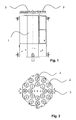
- the recovery device 2 shown in FIGS. 3 and 4 are under a cover 3 in a housing 4 a total of four Guide weights 5 to 8 arranged, which together Clamp catch net 9.
- the Guide weights 5 to 8 in the outer edge area of the network 9 integrated.
- the network 9 is before the start or the triggering the arrangement folded inside the housing. 4 accommodated.
- the guide weights 5 to 8 are how to recognize in particular in Figures 6 and 7, on a Circle equidistant and at an angle to the longitudinal axis of the Housing 4 arranged in its outer edge region.
- Each of the in the case of the embodiment described here four guide weights 5 - 8 has a mass of about one kg and is accelerated via an associated coil spring 10, which is triggered at an opening of the cover 3 and the accelerates the respective leadership weight in one direction, at an angle to the intended trajectory of the network. 9 extends radially outward. To initiate this opening the Cover 3 are a bolt cutter 11 and another, in the Center of the housing 4 arranged spring 12 is provided.
- the net 9 is in turn about one in the case of here described embodiment 60 meters long rope 14 with one arranged on the orbital platform 1 controllable Role connected. This role is in a closed Control circuit by a motor, a traction, the On-board computer of space platform 1 and by a Ground control controlled and controlled.
- Mechanisms that in the case of the here described Embodiment in two of the four guide weights 5 - 8 are integrated and one of which can be seen in Fig. 6, activated to the network 9 above or behind the target object 15 shut down.
- the mechanisms each consist of one Rotor 16, which via an electric motor 17 with low Dimensions, a so-called spin drive, is driven, a battery 18 and a microswitch 19.
- the latter activate a timer, for example after a Duration of about 60 seconds to start the engines 17, so that this one in the edge region of the network 9 between the Weights arranged cord, all four guide weights 5 - 8 connects with each other, start to roll up and so on Net 9, as can be seen in Fig. 9, close so far that the target object 15 in further or opposite Rotational movements are not released again and lost can go.
- a timer for example after a Duration of about 60 seconds to start the engines 17, so that this one in the edge region of the network 9 between the Weights arranged cord, all four guide weights 5 - 8 connects with each other, start to roll up and so on Net 9, as can be seen in Fig. 9, close so far that the target object 15 in further or opposite Rotational movements are not released again and lost can go.
- These are the drives in the guide weights. 5 with anti-reverse devices such as e.g. Worm gears or spindle drives equipped.
- the nets 9 of the individual salvage devices 2 can different diameters of about 10, 15 or more meters and adapted mesh sizes of about 0.3 to 0.5 meters and thus for different sizes of Target objects 15 be suitable.
- Each net 9 is over a rope 14, in the case of the embodiment described here a length of about 60 meters and a thickness of about one Millimeter, connected to the orbital platform 1.
- the on the orbital platform 1 located controllable winds with Engine is used to adjust the rope length and the tractive forces both during the recovery process and the necessary Stabilization of the captured as well as possible subsequent transport operations to control or Taxes. Your assigned are also a Switzerlandkraftmesser and a Bolt cutters.
- a visualization system in the form of a Camera finally allows an operator who To observe and control the capture process.
- the net 9 including the Ropes 14 are separated from the Oritalframe 1 from.
Landscapes
- Engineering & Computer Science (AREA)
- Remote Sensing (AREA)
- Aviation & Aerospace Engineering (AREA)
- Catching Or Destruction (AREA)
- Transition And Organic Metals Composition Catalysts For Addition Polymerization (AREA)
- Emergency Lowering Means (AREA)
Abstract
Description
- Fig. 1 und 2
- eine mit einer Reihe von Bergungsvorrichtungen ausgerüstetes Weltraumplattform,
- Fig. 3 und 4:
- eine der Bergungsvorrichtungen gemäß der Darstellung in Fig. 1 und 2,
- Fig. 5:
- die Bergungsvorrichtungen gemäß den Figuren 3 und 4 in einer Schnittdarstellung,
- Fig. 6 und 7:
- Detaildarstellungen der Bergungsvorrichtung gemäß den Figuren 3 und 4 in zwei unterschiedlichen Zuständen und
- Fig. 8 und 9:
- eine Anordnung gemäß Fig. 1 in zwei verschiedenen Stadien ihres Einsatzes.
Claims (10)
- Bergungsvorrichtung für frei im All fliegende Objekte, mit einem sich selbsttätig entfaltenden, über eine Leine mit einem Raumfahrzeug verbundenen und von diesem zu startenden Fangnetz, das an seinem äußeren Rand mit Gewichten versehen ist, dadurch gekennzeichnet, daß insgesamt wenigstens vier Führungsgewichte (5 - 8) vorgesehen sind, die über einen jeweils zugeordneten Auswurfmechanismus (10) unter einem Winkel zur Bewegungsrichtung des Fangnetzes (9) beschleunigbar sind.
- Vorrichtung nach Anspruch 1, dadurch gekennzeichnet, daß die Führungsgewichte (5 - 8) in einem Gehäuse (4) auf einem Kreis äquidistant und unter einem Winkel zur Längsachse des Gehäuses (4) in dessen äußerem Randbereich angeordnet und jeweils über eine zugeordnete Feder (10) beschleunigbar sind.
- Vorrichtung nach Anspruch 2, dadurch gekennzeichnet, daß die Führungsgewichte (5 - 8) beim Auslösen des Netzes gleichzeitig freigegeben werden.
- Vorrichtung nach Anspruch 2, dadurch gekennzeichnet, daß die Führungsgewichte (5 - 8) sowie das Fangnetz (9) unter einer mit dem Fangnetz (9) verbundenen Abdeckung (3) des Gehäuses (4) angeordnet sind, die ihrerseits über eine zugeordnete Feder (12) beaufschlagbar ist.
- Vorrichtung nach einem der Ansprüche 1 bis 4, dadurch gekennzeichnet, daß in wenigstens zwei der Führungsgewichte (5 - 8) Mechanismen zum Verschließen des Fangnetzes (9) hinter einem Zielobjekt (15) integriert sind.
- Vorrichtung nach Anspruch 5, dadurch gekennzeichnet, daß die Mechanismen jeweils aus einem über einen Elektromotor (17) angetriebenen Rotor (16), einer Batterie (18) sowie einem Mikroschalter 19 bestehen, wobei die Rotoren (16) auf eine die Führungsgewichte (5 - 8) miteinander verbindende Schnur wirken.
- Vorrichtung nach Anspruch 6, dadurch gekennzeichnet, daß die Mechanismen jeweils über einen eigenen voreingestellten Startverzögerungsmechanismus verfügen, der das Verschließen des Fangnetzes bis zu einem passenden Zeitpunkt nach Einfangen des Objektes verschiebt.
- Vorrichtung nach Anspruch 1, dadurch gekennzeichnet, daß die Bergungsvorrichtung über ein in seiner Länge und seinen Zugkräften einstellbares Seil mit der Orbitalplattform verbunden ist.
- Vorrichtung nach Anspruch 8, dadurch gekennzeichnet, daß der Abstand zwischen der Bergungsvorrichtung und der Orbitalplattform über die Länge und die Zugkräfte des Seiles geregelt wird.
- Vorrichtung nach Anspruch 8 und 9, dadurch gekennzeichnet, daß das Seil nach Transport des Objektes an seinen Zielort oder -orbit auf der Orbitalplattformseite abgetrennt wird und so das geborgene Objekt im Netz gesichert aussetzt.
Applications Claiming Priority (2)
| Application Number | Priority Date | Filing Date | Title |
|---|---|---|---|
| DE10342954 | 2003-09-17 | ||
| DE10342954A DE10342954B4 (de) | 2003-09-17 | 2003-09-17 | Bergungsvorrichtung |
Publications (2)
| Publication Number | Publication Date |
|---|---|
| EP1516814A1 true EP1516814A1 (de) | 2005-03-23 |
| EP1516814B1 EP1516814B1 (de) | 2006-11-15 |
Family
ID=34177793
Family Applications (1)
| Application Number | Title | Priority Date | Filing Date |
|---|---|---|---|
| EP04018811A Expired - Lifetime EP1516814B1 (de) | 2003-09-17 | 2004-08-09 | Bergungsvorrichtung |
Country Status (4)
| Country | Link |
|---|---|
| US (1) | US7168660B2 (de) |
| EP (1) | EP1516814B1 (de) |
| AT (1) | ATE345264T1 (de) |
| DE (2) | DE10342954B4 (de) |
Cited By (13)
| Publication number | Priority date | Publication date | Assignee | Title |
|---|---|---|---|---|
| CN103587728A (zh) * | 2013-10-23 | 2014-02-19 | 北京空间飞行器总体设计部 | 绳网式空间碎片抓捕与清除系统 |
| CN103587731A (zh) * | 2013-10-23 | 2014-02-19 | 北京空间飞行器总体设计部 | 一种空间飞网二级发射展开装置 |
| CN103587730A (zh) * | 2013-10-23 | 2014-02-19 | 北京空间飞行器总体设计部 | 一种空间飞网二级发射展开方法 |
| CN104807664A (zh) * | 2015-05-15 | 2015-07-29 | 中国人民解放军国防科学技术大学 | 一种空间飞网发射展开地面试验装置 |
| CN107719708A (zh) * | 2017-09-27 | 2018-02-23 | 西北工业大学深圳研究院 | 一种空间碎片的捕获及清除装置及其方法 |
| CN108516112A (zh) * | 2018-04-08 | 2018-09-11 | 浙江理工大学 | 一种自适应欠驱动式非合作目标空间捕获机构 |
| CN109204892A (zh) * | 2018-10-22 | 2019-01-15 | 北京科技大学 | 一种弹簧蓄能式飞网收口装置 |
| CN109850190A (zh) * | 2019-02-02 | 2019-06-07 | 中国人民解放军国防科技大学 | 空间随形抓捕网 |
| CN110435934A (zh) * | 2019-07-19 | 2019-11-12 | 西北工业大学 | 一种可重复使用的失效卫星回收飞行器 |
| WO2020178614A1 (en) * | 2019-03-01 | 2020-09-10 | Ecole Polytechnique Federale De Lausanne (Epfl) | Capture system adapted to capture orbital objects, in particular for deorbiting purposes |
| CN112455731A (zh) * | 2020-12-22 | 2021-03-09 | 中国人民解放军国防科技大学 | 空间目标捕获装置及空间目标捕获系统 |
| CN114084383A (zh) * | 2021-11-23 | 2022-02-25 | 中国科学院力学研究所 | 一种可控太空套索装置 |
| CN116729651A (zh) * | 2023-05-05 | 2023-09-12 | 上海宇航系统工程研究所 | 一种可伸缩锁喉式卫星喷管捕获连接装置 |
Families Citing this family (52)
| Publication number | Priority date | Publication date | Assignee | Title |
|---|---|---|---|---|
| DE102007041994B4 (de) | 2007-09-04 | 2009-08-13 | Schepelmann, Jürgen | Mechanismus zum Ausschleudern einer Stoßmasse zur Ablenkung eines störenden Satelliten auf eine tolerierbare Bahn durch Kollision |
| US8052092B2 (en) * | 2009-01-30 | 2011-11-08 | The Boeing Company | Method and apparatus for satellite orbital change using space debris |
| US8485475B2 (en) * | 2009-12-16 | 2013-07-16 | Daniel W. Allen | Debris removal management system and method of operation thereof |
| US20140064905A1 (en) * | 2011-01-10 | 2014-03-06 | Sri International | Electroadhesive System for Capturing Objects |
| DE102011013875A1 (de) | 2011-03-08 | 2012-09-13 | Astrium Gmbh | Bergungs- und Abbremsvorrichtung für frei im All fliegende Objekte |
| US8979034B2 (en) * | 2011-12-06 | 2015-03-17 | Altius Space Machines | Sticky boom non-cooperative capture device |
| US8967548B2 (en) * | 2011-12-06 | 2015-03-03 | Altius Space Machines | Direct to facility capture and release |
| CN102658873B (zh) * | 2012-05-10 | 2014-08-27 | 中国人民解放军国防科学技术大学 | 一种用于捕获太空垃圾的绳网系统 |
| FR2991671B1 (fr) * | 2012-06-08 | 2015-04-03 | Bertin Technologies Sa | Procede et dispositif de capture et de couplage en vue de la desorbitation ou reorbitation d'un objet dans l'espace |
| US9187189B2 (en) | 2012-10-12 | 2015-11-17 | The Aerospace Corporation | System, apparatus, and method for active debris removal |
| CN102991731A (zh) * | 2012-12-17 | 2013-03-27 | 北京理工大学 | 一种用于废弃航天器捕获的飞网弹射捕获装置 |
| US9434485B1 (en) * | 2013-01-25 | 2016-09-06 | Stephen C. Lehocki | Multi-purpose cargo delivery and space debris removal system |
| CN103407587B (zh) * | 2013-08-06 | 2015-07-29 | 北京航空航天大学 | 一种空间柔性网捕装置发射展开系统 |
| US10696425B2 (en) | 2013-08-09 | 2020-06-30 | The Aerospace Corporation | System for imparting linear momentum transfer for higher orbital insertion |
| US9260204B2 (en) * | 2013-08-09 | 2016-02-16 | The Aerospace Corporation | Kinetic energy storage and transfer (KEST) space launch system |
| CN103587729B (zh) * | 2013-10-23 | 2015-10-21 | 北京航空航天大学 | 一种用于空间飞网收口的双驱并置收线装置 |
| US9038959B2 (en) * | 2013-10-28 | 2015-05-26 | Fukashi Andoh | Space debris remover |
| US9187191B1 (en) * | 2014-12-01 | 2015-11-17 | Duane Lowell Jensen | Stretch skin receptacle for space object capture and release |
| WO2016172647A1 (en) * | 2015-04-22 | 2016-10-27 | Sercel Joel C | Optics and structure for space applications |
| CN106335657B (zh) * | 2015-07-09 | 2021-04-06 | 北京空间飞行器总体设计部 | 六牵引装置空间碎片网捕系统 |
| CN109071041B (zh) | 2016-02-29 | 2022-08-23 | 乐加德公司 | 紧凑型rf薄膜天线 |
| WO2017192200A1 (en) | 2016-05-05 | 2017-11-09 | The Research Foundation For The State Unversity Of New York | Compositions for treating periodontitis and dental calculus accumulation |
| KR101749058B1 (ko) | 2016-11-18 | 2017-07-03 | 박정환 | 우주쓰레기 처리장치 |
| CN107264839B (zh) * | 2017-05-18 | 2019-06-28 | 上海卫星工程研究所 | 卫星推进管路布局方法 |
| CN107200148B (zh) * | 2017-05-27 | 2018-06-29 | 中国人民解放军国防科学技术大学 | 在轨抓捕用仿生蛛网及其收纳方法 |
| EP3752423A4 (de) * | 2018-02-15 | 2021-11-17 | L'garde Inc. | Weltraummüllaufnahme und deorbitingsystem |
| US20200017242A1 (en) * | 2018-07-16 | 2020-01-16 | Jonathan Armstead | Orbital radiation shield enclosure |
| CN109625339B (zh) * | 2018-12-29 | 2022-04-15 | 西北工业大学 | 一种可控旋转角速度的微纳卫星分离装置 |
| EP4022713A4 (de) | 2019-08-30 | 2023-08-23 | L'garde, Inc. | Kompaktierbare antenne zur satellitenkommunikation |
| WO2021173229A1 (en) | 2020-02-24 | 2021-09-02 | L'garde, Inc. | Connection assembly |
| JP7773539B2 (ja) | 2020-10-14 | 2025-11-19 | ルギャルド,インク. | 宇宙での展開のためのコンパクト化可能構造 |
| CN112896561B (zh) * | 2021-01-29 | 2022-12-06 | 中国人民解放军国防科技大学 | 一种空间飞网发射装置及发射方法 |
| CN112896562B (zh) * | 2021-02-11 | 2022-10-14 | 西北工业大学 | 一种基于惯性的空间碎片绳系捕获器 |
| CN113277129B (zh) * | 2021-05-31 | 2022-07-05 | 北京理工大学 | 一种可调节发射角度的飞网弹射装置 |
| JP6968377B1 (ja) * | 2021-07-05 | 2021-11-17 | 東京都公立大学法人 | 網射出装置、網発射装置の設計方法および宇宙デブリ・不審飛行体の捕獲・処理方法 |
| WO2023281632A1 (ja) * | 2021-07-06 | 2023-01-12 | 三菱電機株式会社 | 捕獲装置および宇宙機 |
| CN113524160B (zh) * | 2021-07-20 | 2022-03-08 | 哈尔滨工业大学 | 动量自适应隔离缓释型空间抓捕装置 |
| US12017803B2 (en) | 2021-07-28 | 2024-06-25 | Rensselaer Polytechnic Institute | System and method for debris capture |
| CN113716075B (zh) * | 2021-08-10 | 2023-03-14 | 南京信息工程大学 | 一种基于机器人编队的太空垃圾智能清理系统 |
| CN113895662B (zh) * | 2021-10-11 | 2023-06-06 | 北京空间飞行器总体设计部 | 一种失效卫星捕获对接装置及方法 |
| US12549126B2 (en) | 2021-11-12 | 2026-02-10 | L'garde, Inc. | Lightweight, low stow volume, deployable solar concentrator for space applications |
| JP7067749B1 (ja) | 2021-11-30 | 2022-05-16 | 東京都公立大学法人 | 射出角度変更可能な網射出装置 |
| CN113955160B (zh) * | 2021-12-10 | 2023-06-16 | 北京科技大学 | 用于深空探测的可折展捕获装置及其操控方法 |
| CN114132506B (zh) * | 2021-12-31 | 2025-01-03 | 长春长光博翔无人机有限公司 | 机载反无人机的目标捕获装置及其方法 |
| CN114715446B (zh) * | 2022-03-24 | 2025-09-19 | 北京精密机电控制设备研究所 | 一种用于空间碎片消旋的全向可控轮式末端执行器 |
| CN114543601B (zh) * | 2022-03-28 | 2023-09-29 | 北京中科宇航技术有限公司 | 一种低冲爆炸螺栓解锁捕获装置 |
| CN115779288B (zh) * | 2022-11-18 | 2023-09-26 | 南京理工大学 | 一种适用于空间非合作目标捕获的可收口自主机动绳网 |
| CN115959308B (zh) * | 2023-01-31 | 2024-03-22 | 北京理工大学 | 一种低成本电驱动的电动力绳释放装置及离轨实验装置 |
| CN116119042B (zh) * | 2023-04-19 | 2023-07-07 | 中国科学院沈阳自动化研究所 | 一种飞网式空间碎片捕获装置 |
| WO2025071688A2 (en) * | 2023-05-23 | 2025-04-03 | Trans Astronautica Corporation | Systems and methods for capturing space objects |
| CN116946423B (zh) * | 2023-06-26 | 2025-10-31 | 杭州电子科技大学 | 基于自旋展开式绳网的无人机捕获系统 |
| CN117284505B (zh) * | 2023-11-13 | 2025-11-07 | 燕山大学 | 单元阵列集成式单自由度空间捕获手 |
Citations (2)
| Publication number | Priority date | Publication date | Assignee | Title |
|---|---|---|---|---|
| US5279482A (en) * | 1992-06-05 | 1994-01-18 | The United States Of America As Represented By The Administrator Of The National Aeronautics And Space Administration | Fingered bola body, bola with same, and methods of use |
| JPH07251799A (ja) * | 1994-03-16 | 1995-10-03 | Toshiba Corp | 宇宙航行体 |
Family Cites Families (6)
| Publication number | Priority date | Publication date | Assignee | Title |
|---|---|---|---|---|
| US3004735A (en) * | 1959-12-21 | 1961-10-17 | William H Kinard | Particle detection apparatus |
| US4750692A (en) * | 1987-04-07 | 1988-06-14 | Howard Thomas R | Satellite retrieval apparatus |
| USH1383H (en) * | 1992-03-31 | 1994-12-06 | United States Of America | Space-based tethered phased-array antenna |
| US5865401A (en) * | 1996-08-29 | 1999-02-02 | Space Systems/Loral, Inc. | Tethered space platform assembly for isolation orbiting |
| US6299107B1 (en) * | 1998-12-04 | 2001-10-09 | Honeybee Robotics, Ltd. | Spacecraft capture and docking system |
| US6655637B1 (en) * | 2002-06-24 | 2003-12-02 | The Aerospace Corporation | Spacecraft for removal of space orbital debris |
-
2003
- 2003-09-17 DE DE10342954A patent/DE10342954B4/de not_active Expired - Fee Related
-
2004
- 2004-08-09 DE DE502004001992T patent/DE502004001992D1/de not_active Expired - Lifetime
- 2004-08-09 EP EP04018811A patent/EP1516814B1/de not_active Expired - Lifetime
- 2004-08-09 AT AT04018811T patent/ATE345264T1/de not_active IP Right Cessation
- 2004-09-17 US US10/943,769 patent/US7168660B2/en not_active Expired - Lifetime
Patent Citations (2)
| Publication number | Priority date | Publication date | Assignee | Title |
|---|---|---|---|---|
| US5279482A (en) * | 1992-06-05 | 1994-01-18 | The United States Of America As Represented By The Administrator Of The National Aeronautics And Space Administration | Fingered bola body, bola with same, and methods of use |
| JPH07251799A (ja) * | 1994-03-16 | 1995-10-03 | Toshiba Corp | 宇宙航行体 |
Non-Patent Citations (1)
| Title |
|---|
| DATABASE WPI Section PQ Week 199549, Derwent World Patents Index; Class Q25, AN 1995-377542, XP002304269 * |
Cited By (20)
| Publication number | Priority date | Publication date | Assignee | Title |
|---|---|---|---|---|
| CN103587728A (zh) * | 2013-10-23 | 2014-02-19 | 北京空间飞行器总体设计部 | 绳网式空间碎片抓捕与清除系统 |
| CN103587731A (zh) * | 2013-10-23 | 2014-02-19 | 北京空间飞行器总体设计部 | 一种空间飞网二级发射展开装置 |
| CN103587730A (zh) * | 2013-10-23 | 2014-02-19 | 北京空间飞行器总体设计部 | 一种空间飞网二级发射展开方法 |
| CN103587730B (zh) * | 2013-10-23 | 2015-11-25 | 北京空间飞行器总体设计部 | 一种空间飞网二级发射展开方法 |
| CN103587731B (zh) * | 2013-10-23 | 2015-11-25 | 北京空间飞行器总体设计部 | 一种空间飞网二级发射展开装置 |
| CN104807664A (zh) * | 2015-05-15 | 2015-07-29 | 中国人民解放军国防科学技术大学 | 一种空间飞网发射展开地面试验装置 |
| CN107719708A (zh) * | 2017-09-27 | 2018-02-23 | 西北工业大学深圳研究院 | 一种空间碎片的捕获及清除装置及其方法 |
| CN108516112A (zh) * | 2018-04-08 | 2018-09-11 | 浙江理工大学 | 一种自适应欠驱动式非合作目标空间捕获机构 |
| CN108516112B (zh) * | 2018-04-08 | 2023-11-07 | 浙江理工大学 | 一种自适应欠驱动式非合作目标空间捕获机构 |
| CN109204892A (zh) * | 2018-10-22 | 2019-01-15 | 北京科技大学 | 一种弹簧蓄能式飞网收口装置 |
| CN109204892B (zh) * | 2018-10-22 | 2020-04-24 | 北京科技大学 | 一种弹簧蓄能式飞网收口装置 |
| CN109850190A (zh) * | 2019-02-02 | 2019-06-07 | 中国人民解放军国防科技大学 | 空间随形抓捕网 |
| CN109850190B (zh) * | 2019-02-02 | 2020-09-18 | 中国人民解放军国防科技大学 | 空间随形抓捕装置 |
| WO2020178614A1 (en) * | 2019-03-01 | 2020-09-10 | Ecole Polytechnique Federale De Lausanne (Epfl) | Capture system adapted to capture orbital objects, in particular for deorbiting purposes |
| CN110435934A (zh) * | 2019-07-19 | 2019-11-12 | 西北工业大学 | 一种可重复使用的失效卫星回收飞行器 |
| CN110435934B (zh) * | 2019-07-19 | 2021-02-19 | 西北工业大学 | 一种可重复使用的失效卫星回收飞行器 |
| CN112455731A (zh) * | 2020-12-22 | 2021-03-09 | 中国人民解放军国防科技大学 | 空间目标捕获装置及空间目标捕获系统 |
| CN114084383A (zh) * | 2021-11-23 | 2022-02-25 | 中国科学院力学研究所 | 一种可控太空套索装置 |
| CN114084383B (zh) * | 2021-11-23 | 2023-12-08 | 中国科学院力学研究所 | 一种可控太空套索装置 |
| CN116729651A (zh) * | 2023-05-05 | 2023-09-12 | 上海宇航系统工程研究所 | 一种可伸缩锁喉式卫星喷管捕获连接装置 |
Also Published As
| Publication number | Publication date |
|---|---|
| DE10342954B4 (de) | 2005-07-28 |
| EP1516814B1 (de) | 2006-11-15 |
| ATE345264T1 (de) | 2006-12-15 |
| US20050103939A1 (en) | 2005-05-19 |
| DE502004001992D1 (de) | 2006-12-28 |
| DE10342954A1 (de) | 2005-04-21 |
| US7168660B2 (en) | 2007-01-30 |
Similar Documents
| Publication | Publication Date | Title |
|---|---|---|
| DE10342954B4 (de) | Bergungsvorrichtung | |
| EP2497714B1 (de) | Bergungs- und Abbremsvorrichtung für frei im All fliegende Objekte | |
| DE10342953B4 (de) | Vorrichtung zum Greifen von Objekten im All | |
| DE19856670B4 (de) | Vorrichtung zum Aussetzen von Satelliten | |
| DE102010010161B4 (de) | Auslösevorrichtung für eine Last an einer Einrichtung und Unterwassereinrichtung | |
| WO2018099604A1 (de) | Startanordnung für einen flugkörper zum abfangen von fremddrohnen | |
| DE102011100971A1 (de) | Vorrichtung zum Einfangen von Weltraum-Müll | |
| DE1800121C3 (de) | Vorrichtung zur definierten Positionierung von Abwurfkörpern, insbesondere Sprengladungen | |
| DE2115501B2 (de) | Schleudersitz, insbesondere fuer hubschrauber | |
| EP1167820B1 (de) | Linearbetätigungsvorrichtung, insbesondere für Solargenerator-Entfaltsysteme für Raumfahrzeuge | |
| DE2234849B2 (de) | Von einem Windradgenerator gespeiste Zündeinrichtung, insbesondere für aus Flugzeugen abwerfbare Bomblets | |
| DE102018106058B4 (de) | Verfahren zur Unterstützung eines Luftfahrzeug-Einsatzes mittels eines unbemannten Fluggerätes | |
| EP2312256A2 (de) | Flugkörperstartvorrichtung | |
| EP3252259B1 (de) | Antriebsvorrichtung eines rollladens und rollladen | |
| DE102007041994B4 (de) | Mechanismus zum Ausschleudern einer Stoßmasse zur Ablenkung eines störenden Satelliten auf eine tolerierbare Bahn durch Kollision | |
| EP4339551A1 (de) | Vorrichtung und verfahren zur abwehr von fliegenden objekten | |
| DE102019135246B4 (de) | Fluggerät und Verfahren zum Abfangen einer Drohne | |
| EP0690285A1 (de) | Verfahren und Vorrichtung zum Auslösen von Lawinen mittels Explosivladungen | |
| EP0389852A2 (de) | Mine mit Sensordraht-Verlegeeinheit | |
| DE102022121276B4 (de) | Fallschirmvorrichtung für ein unbemanntes Luftfahrzeug | |
| DE2043869B2 (de) | Notvorrichtung zum AbscMeudern oder Schnellöffnen eines Abschnittes einer Fahrzeugkanzel, insbesondere des Kanzeldaches eines Luftfahrzeuges | |
| DE202017001485U1 (de) | Ausstoßvorrichtung | |
| DE1506010C3 (de) | ||
| DE723316C (de) | Fuer Luftfahrzeuge bestimmte Trag- und Abwurfvorrichtung fuer einen aus seiner Tragstellung unmittelbar frei fallenden, beim Abwurf auf Anlassen gesteuerten Torpedo | |
| AT407571B (de) | Verfahren zum räumen eines minenfeldes |
Legal Events
| Date | Code | Title | Description |
|---|---|---|---|
| PUAI | Public reference made under article 153(3) epc to a published international application that has entered the european phase |
Free format text: ORIGINAL CODE: 0009012 |
|
| 17P | Request for examination filed |
Effective date: 20041214 |
|
| AK | Designated contracting states |
Kind code of ref document: A1 Designated state(s): AT BE BG CH CY CZ DE DK EE ES FI FR GB GR HU IE IT LI LU MC NL PL PT RO SE SI SK TR |
|
| AX | Request for extension of the european patent |
Extension state: AL HR LT LV MK |
|
| AKX | Designation fees paid |
Designated state(s): AT BE BG CH CY CZ DE DK EE ES FI FR GB GR HU IE IT LI LU MC NL PL PT RO SE SI SK TR |
|
| GRAP | Despatch of communication of intention to grant a patent |
Free format text: ORIGINAL CODE: EPIDOSNIGR1 |
|
| GRAS | Grant fee paid |
Free format text: ORIGINAL CODE: EPIDOSNIGR3 |
|
| GRAA | (expected) grant |
Free format text: ORIGINAL CODE: 0009210 |
|
| AK | Designated contracting states |
Kind code of ref document: B1 Designated state(s): AT BE BG CH CY CZ DE DK EE ES FI FR GB GR HU IE IT LI LU MC NL PL PT RO SE SI SK TR |
|
| PG25 | Lapsed in a contracting state [announced via postgrant information from national office to epo] |
Ref country code: PL Free format text: LAPSE BECAUSE OF FAILURE TO SUBMIT A TRANSLATION OF THE DESCRIPTION OR TO PAY THE FEE WITHIN THE PRESCRIBED TIME-LIMIT Effective date: 20061115 Ref country code: CZ Free format text: LAPSE BECAUSE OF FAILURE TO SUBMIT A TRANSLATION OF THE DESCRIPTION OR TO PAY THE FEE WITHIN THE PRESCRIBED TIME-LIMIT Effective date: 20061115 Ref country code: RO Free format text: LAPSE BECAUSE OF FAILURE TO SUBMIT A TRANSLATION OF THE DESCRIPTION OR TO PAY THE FEE WITHIN THE PRESCRIBED TIME-LIMIT Effective date: 20061115 Ref country code: IE Free format text: LAPSE BECAUSE OF FAILURE TO SUBMIT A TRANSLATION OF THE DESCRIPTION OR TO PAY THE FEE WITHIN THE PRESCRIBED TIME-LIMIT Effective date: 20061115 Ref country code: SK Free format text: LAPSE BECAUSE OF FAILURE TO SUBMIT A TRANSLATION OF THE DESCRIPTION OR TO PAY THE FEE WITHIN THE PRESCRIBED TIME-LIMIT Effective date: 20061115 Ref country code: FI Free format text: LAPSE BECAUSE OF FAILURE TO SUBMIT A TRANSLATION OF THE DESCRIPTION OR TO PAY THE FEE WITHIN THE PRESCRIBED TIME-LIMIT Effective date: 20061115 Ref country code: SI Free format text: LAPSE BECAUSE OF FAILURE TO SUBMIT A TRANSLATION OF THE DESCRIPTION OR TO PAY THE FEE WITHIN THE PRESCRIBED TIME-LIMIT Effective date: 20061115 |
|
| REG | Reference to a national code |
Ref country code: GB Ref legal event code: FG4D Free format text: NOT ENGLISH |
|
| REG | Reference to a national code |
Ref country code: CH Ref legal event code: EP |
|
| REF | Corresponds to: |
Ref document number: 502004001992 Country of ref document: DE Date of ref document: 20061228 Kind code of ref document: P |
|
| REG | Reference to a national code |
Ref country code: IE Ref legal event code: FG4D Free format text: LANGUAGE OF EP DOCUMENT: GERMAN |
|
| RAP2 | Party data changed (patent owner data changed or rights of a patent transferred) |
Owner name: ASTRIUM GMBH |
|
| PG25 | Lapsed in a contracting state [announced via postgrant information from national office to epo] |
Ref country code: DK Free format text: LAPSE BECAUSE OF FAILURE TO SUBMIT A TRANSLATION OF THE DESCRIPTION OR TO PAY THE FEE WITHIN THE PRESCRIBED TIME-LIMIT Effective date: 20070215 Ref country code: BG Free format text: LAPSE BECAUSE OF FAILURE TO SUBMIT A TRANSLATION OF THE DESCRIPTION OR TO PAY THE FEE WITHIN THE PRESCRIBED TIME-LIMIT Effective date: 20070215 Ref country code: SE Free format text: LAPSE BECAUSE OF FAILURE TO SUBMIT A TRANSLATION OF THE DESCRIPTION OR TO PAY THE FEE WITHIN THE PRESCRIBED TIME-LIMIT Effective date: 20070215 |
|
| PG25 | Lapsed in a contracting state [announced via postgrant information from national office to epo] |
Ref country code: ES Free format text: LAPSE BECAUSE OF FAILURE TO SUBMIT A TRANSLATION OF THE DESCRIPTION OR TO PAY THE FEE WITHIN THE PRESCRIBED TIME-LIMIT Effective date: 20070226 |
|
| GBT | Gb: translation of ep patent filed (gb section 77(6)(a)/1977) |
Effective date: 20070207 |
|
| NLT2 | Nl: modifications (of names), taken from the european patent patent bulletin |
Owner name: ASTRIUM GMBH Effective date: 20070124 |
|
| PG25 | Lapsed in a contracting state [announced via postgrant information from national office to epo] |
Ref country code: PT Free format text: LAPSE BECAUSE OF FAILURE TO SUBMIT A TRANSLATION OF THE DESCRIPTION OR TO PAY THE FEE WITHIN THE PRESCRIBED TIME-LIMIT Effective date: 20070416 |
|
| ET | Fr: translation filed | ||
| REG | Reference to a national code |
Ref country code: IE Ref legal event code: FD4D |
|
| PLBE | No opposition filed within time limit |
Free format text: ORIGINAL CODE: 0009261 |
|
| STAA | Information on the status of an ep patent application or granted ep patent |
Free format text: STATUS: NO OPPOSITION FILED WITHIN TIME LIMIT |
|
| 26N | No opposition filed |
Effective date: 20070817 |
|
| PG25 | Lapsed in a contracting state [announced via postgrant information from national office to epo] |
Ref country code: GR Free format text: LAPSE BECAUSE OF FAILURE TO SUBMIT A TRANSLATION OF THE DESCRIPTION OR TO PAY THE FEE WITHIN THE PRESCRIBED TIME-LIMIT Effective date: 20070216 Ref country code: MC Free format text: LAPSE BECAUSE OF NON-PAYMENT OF DUE FEES Effective date: 20070831 |
|
| PG25 | Lapsed in a contracting state [announced via postgrant information from national office to epo] |
Ref country code: AT Free format text: LAPSE BECAUSE OF NON-PAYMENT OF DUE FEES Effective date: 20070809 |
|
| PG25 | Lapsed in a contracting state [announced via postgrant information from national office to epo] |
Ref country code: EE Free format text: LAPSE BECAUSE OF FAILURE TO SUBMIT A TRANSLATION OF THE DESCRIPTION OR TO PAY THE FEE WITHIN THE PRESCRIBED TIME-LIMIT Effective date: 20061115 |
|
| REG | Reference to a national code |
Ref country code: CH Ref legal event code: PL |
|
| PG25 | Lapsed in a contracting state [announced via postgrant information from national office to epo] |
Ref country code: CH Free format text: LAPSE BECAUSE OF NON-PAYMENT OF DUE FEES Effective date: 20080831 Ref country code: LI Free format text: LAPSE BECAUSE OF NON-PAYMENT OF DUE FEES Effective date: 20080831 |
|
| PG25 | Lapsed in a contracting state [announced via postgrant information from national office to epo] |
Ref country code: CY Free format text: LAPSE BECAUSE OF FAILURE TO SUBMIT A TRANSLATION OF THE DESCRIPTION OR TO PAY THE FEE WITHIN THE PRESCRIBED TIME-LIMIT Effective date: 20061115 Ref country code: LU Free format text: LAPSE BECAUSE OF NON-PAYMENT OF DUE FEES Effective date: 20070809 |
|
| PG25 | Lapsed in a contracting state [announced via postgrant information from national office to epo] |
Ref country code: TR Free format text: LAPSE BECAUSE OF FAILURE TO SUBMIT A TRANSLATION OF THE DESCRIPTION OR TO PAY THE FEE WITHIN THE PRESCRIBED TIME-LIMIT Effective date: 20061115 Ref country code: HU Free format text: LAPSE BECAUSE OF FAILURE TO SUBMIT A TRANSLATION OF THE DESCRIPTION OR TO PAY THE FEE WITHIN THE PRESCRIBED TIME-LIMIT Effective date: 20070516 |
|
| PGFP | Annual fee paid to national office [announced via postgrant information from national office to epo] |
Ref country code: NL Payment date: 20140829 Year of fee payment: 11 |
|
| PGFP | Annual fee paid to national office [announced via postgrant information from national office to epo] |
Ref country code: GB Payment date: 20140728 Year of fee payment: 11 |
|
| PGFP | Annual fee paid to national office [announced via postgrant information from national office to epo] |
Ref country code: BE Payment date: 20140812 Year of fee payment: 11 |
|
| GBPC | Gb: european patent ceased through non-payment of renewal fee |
Effective date: 20150809 |
|
| REG | Reference to a national code |
Ref country code: NL Ref legal event code: MM Effective date: 20150901 |
|
| PG25 | Lapsed in a contracting state [announced via postgrant information from national office to epo] |
Ref country code: NL Free format text: LAPSE BECAUSE OF NON-PAYMENT OF DUE FEES Effective date: 20150901 |
|
| PG25 | Lapsed in a contracting state [announced via postgrant information from national office to epo] |
Ref country code: GB Free format text: LAPSE BECAUSE OF NON-PAYMENT OF DUE FEES Effective date: 20150809 |
|
| REG | Reference to a national code |
Ref country code: FR Ref legal event code: PLFP Year of fee payment: 13 |
|
| REG | Reference to a national code |
Ref country code: DE Ref legal event code: R082 Ref document number: 502004001992 Country of ref document: DE Representative=s name: ELBPATENT-MARSCHALL & PARTNER MBB, DE |
|
| PG25 | Lapsed in a contracting state [announced via postgrant information from national office to epo] |
Ref country code: BE Free format text: LAPSE BECAUSE OF NON-PAYMENT OF DUE FEES Effective date: 20150831 |
|
| REG | Reference to a national code |
Ref country code: DE Ref legal event code: R082 Ref document number: 502004001992 Country of ref document: DE Representative=s name: ELBPATENT-MARSCHALL & PARTNER MBB, DE Ref country code: DE Ref legal event code: R081 Ref document number: 502004001992 Country of ref document: DE Owner name: AIRBUS DEFENCE AND SPACE GMBH, DE Free format text: FORMER OWNER: EADS SPACE TRANSPORTATION GMBH, 28199 BREMEN, DE |
|
| REG | Reference to a national code |
Ref country code: FR Ref legal event code: PLFP Year of fee payment: 14 |
|
| REG | Reference to a national code |
Ref country code: FR Ref legal event code: TP Owner name: AIRBUS DS GMBH, DE Effective date: 20180717 |
|
| REG | Reference to a national code |
Ref country code: FR Ref legal event code: CD Owner name: AIRBUS DS GMBH, DE Effective date: 20180718 Ref country code: FR Ref legal event code: PLFP Year of fee payment: 15 |
|
| PGFP | Annual fee paid to national office [announced via postgrant information from national office to epo] |
Ref country code: IT Payment date: 20220825 Year of fee payment: 19 Ref country code: DE Payment date: 20220819 Year of fee payment: 19 |
|
| PGFP | Annual fee paid to national office [announced via postgrant information from national office to epo] |
Ref country code: FR Payment date: 20220823 Year of fee payment: 19 |
|
| REG | Reference to a national code |
Ref country code: DE Ref legal event code: R119 Ref document number: 502004001992 Country of ref document: DE |
|
| PG25 | Lapsed in a contracting state [announced via postgrant information from national office to epo] |
Ref country code: IT Free format text: LAPSE BECAUSE OF NON-PAYMENT OF DUE FEES Effective date: 20230809 Ref country code: FR Free format text: LAPSE BECAUSE OF NON-PAYMENT OF DUE FEES Effective date: 20230831 Ref country code: DE Free format text: LAPSE BECAUSE OF NON-PAYMENT OF DUE FEES Effective date: 20240301 |