EP1516799A1 - Direction assistée électrique et procédé pour compenser l'angle correspondant - Google Patents
Direction assistée électrique et procédé pour compenser l'angle correspondant Download PDFInfo
- Publication number
- EP1516799A1 EP1516799A1 EP04022072A EP04022072A EP1516799A1 EP 1516799 A1 EP1516799 A1 EP 1516799A1 EP 04022072 A EP04022072 A EP 04022072A EP 04022072 A EP04022072 A EP 04022072A EP 1516799 A1 EP1516799 A1 EP 1516799A1
- Authority
- EP
- European Patent Office
- Prior art keywords
- angle
- resolver
- torsion
- electric power
- value
- Prior art date
- Legal status (The legal status is an assumption and is not a legal conclusion. Google has not performed a legal analysis and makes no representation as to the accuracy of the status listed.)
- Granted
Links
- 230000007257 malfunction Effects 0.000 claims description 15
- 230000014509 gene expression Effects 0.000 claims description 7
- 238000001514 detection method Methods 0.000 description 8
- 230000003247 decreasing effect Effects 0.000 description 1
- 238000010586 diagram Methods 0.000 description 1
- 230000000694 effects Effects 0.000 description 1
- 230000005284 excitation Effects 0.000 description 1
- 238000005096 rolling process Methods 0.000 description 1
- 238000004804 winding Methods 0.000 description 1
Images


Classifications
-
- B—PERFORMING OPERATIONS; TRANSPORTING
- B62—LAND VEHICLES FOR TRAVELLING OTHERWISE THAN ON RAILS
- B62D—MOTOR VEHICLES; TRAILERS
- B62D5/00—Power-assisted or power-driven steering
- B62D5/04—Power-assisted or power-driven steering electrical, e.g. using an electric servo-motor connected to, or forming part of, the steering gear
- B62D5/0457—Power-assisted or power-driven steering electrical, e.g. using an electric servo-motor connected to, or forming part of, the steering gear characterised by control features of the drive means as such
- B62D5/0481—Power-assisted or power-driven steering electrical, e.g. using an electric servo-motor connected to, or forming part of, the steering gear characterised by control features of the drive means as such monitoring the steering system, e.g. failures
- B62D5/049—Power-assisted or power-driven steering electrical, e.g. using an electric servo-motor connected to, or forming part of, the steering gear characterised by control features of the drive means as such monitoring the steering system, e.g. failures detecting sensor failures
-
- B—PERFORMING OPERATIONS; TRANSPORTING
- B62—LAND VEHICLES FOR TRAVELLING OTHERWISE THAN ON RAILS
- B62D—MOTOR VEHICLES; TRAILERS
- B62D15/00—Steering not otherwise provided for
- B62D15/02—Steering position indicators ; Steering position determination; Steering aids
- B62D15/021—Determination of steering angle
- B62D15/0215—Determination of steering angle by measuring on the steering column
-
- B—PERFORMING OPERATIONS; TRANSPORTING
- B62—LAND VEHICLES FOR TRAVELLING OTHERWISE THAN ON RAILS
- B62D—MOTOR VEHICLES; TRAILERS
- B62D6/00—Arrangements for automatically controlling steering depending on driving conditions sensed and responded to, e.g. control circuits
- B62D6/08—Arrangements for automatically controlling steering depending on driving conditions sensed and responded to, e.g. control circuits responsive only to driver input torque
- B62D6/10—Arrangements for automatically controlling steering depending on driving conditions sensed and responded to, e.g. control circuits responsive only to driver input torque characterised by means for sensing or determining torque
-
- G—PHYSICS
- G01—MEASURING; TESTING
- G01L—MEASURING FORCE, STRESS, TORQUE, WORK, MECHANICAL POWER, MECHANICAL EFFICIENCY, OR FLUID PRESSURE
- G01L3/00—Measuring torque, work, mechanical power, or mechanical efficiency, in general
- G01L3/02—Rotary-transmission dynamometers
- G01L3/04—Rotary-transmission dynamometers wherein the torque-transmitting element comprises a torsionally-flexible shaft
- G01L3/10—Rotary-transmission dynamometers wherein the torque-transmitting element comprises a torsionally-flexible shaft involving electric or magnetic means for indicating
- G01L3/101—Rotary-transmission dynamometers wherein the torque-transmitting element comprises a torsionally-flexible shaft involving electric or magnetic means for indicating involving magnetic or electromagnetic means
- G01L3/104—Rotary-transmission dynamometers wherein the torque-transmitting element comprises a torsionally-flexible shaft involving electric or magnetic means for indicating involving magnetic or electromagnetic means involving permanent magnets
-
- G—PHYSICS
- G01—MEASURING; TESTING
- G01L—MEASURING FORCE, STRESS, TORQUE, WORK, MECHANICAL POWER, MECHANICAL EFFICIENCY, OR FLUID PRESSURE
- G01L3/00—Measuring torque, work, mechanical power, or mechanical efficiency, in general
- G01L3/02—Rotary-transmission dynamometers
- G01L3/04—Rotary-transmission dynamometers wherein the torque-transmitting element comprises a torsionally-flexible shaft
- G01L3/10—Rotary-transmission dynamometers wherein the torque-transmitting element comprises a torsionally-flexible shaft involving electric or magnetic means for indicating
- G01L3/101—Rotary-transmission dynamometers wherein the torque-transmitting element comprises a torsionally-flexible shaft involving electric or magnetic means for indicating involving magnetic or electromagnetic means
- G01L3/105—Rotary-transmission dynamometers wherein the torque-transmitting element comprises a torsionally-flexible shaft involving electric or magnetic means for indicating involving magnetic or electromagnetic means involving inductive means
-
- G—PHYSICS
- G01—MEASURING; TESTING
- G01L—MEASURING FORCE, STRESS, TORQUE, WORK, MECHANICAL POWER, MECHANICAL EFFICIENCY, OR FLUID PRESSURE
- G01L3/00—Measuring torque, work, mechanical power, or mechanical efficiency, in general
- G01L3/02—Rotary-transmission dynamometers
- G01L3/04—Rotary-transmission dynamometers wherein the torque-transmitting element comprises a torsionally-flexible shaft
- G01L3/10—Rotary-transmission dynamometers wherein the torque-transmitting element comprises a torsionally-flexible shaft involving electric or magnetic means for indicating
- G01L3/109—Rotary-transmission dynamometers wherein the torque-transmitting element comprises a torsionally-flexible shaft involving electric or magnetic means for indicating involving measuring phase difference of two signals or pulse trains
-
- G—PHYSICS
- G01—MEASURING; TESTING
- G01L—MEASURING FORCE, STRESS, TORQUE, WORK, MECHANICAL POWER, MECHANICAL EFFICIENCY, OR FLUID PRESSURE
- G01L5/00—Apparatus for, or methods of, measuring force, work, mechanical power, or torque, specially adapted for specific purposes
- G01L5/22—Apparatus for, or methods of, measuring force, work, mechanical power, or torque, specially adapted for specific purposes for measuring the force applied to control members, e.g. control members of vehicles, triggers
- G01L5/221—Apparatus for, or methods of, measuring force, work, mechanical power, or torque, specially adapted for specific purposes for measuring the force applied to control members, e.g. control members of vehicles, triggers to steering wheels, e.g. for power assisted steering
Definitions
- the present invention relates to an electric power steering apparatus for detecting steering torque on the basis of a difference between rotating angles of first and second resolvers which are located at both ends of a torsion bar connected to a steering wheel, and for assisting a steering operation by controlling a motor in accordance with assist amount determined on the basis of the steering torque.
- an electric power steering apparatus which reduces steering force through a steering wheel by providing a steering mechanism connected to a steering shaft with assist force by a motor, has been known.
- a torque sensor using a torsion bar may be employed for detecting a steering torque.
- the torsion bar with a pair of rotating angle sensors is disposed between the steering shaft and a steering gear box.
- Torsion of the torsion bar i.e. the steering torque, is calculated from difference between rotating angles detected by first and second rotating angel sensors.
- resolvers can be employed because of its high mechanical reliability.
- the electric power steering apparatus having the aforementioned structure is described in Japanese Patent Laid-Open Publication No. 11-321689.
- a malfunction of the sensor is detected in such a way that described in Japanese Patent Laid-Open Publication No. 8-289521 or No. 8-210874.
- the resolver including winding coils is a kind of the electrical transformer, amplitudes of Sin phase signal and Cos phase signal vary in accordance with temperature variation. Therefore, a threshold value for aforementioned malfunction judging is needed to set at a value that temperature variation offset value T is added to the C (constant value).
- the temperature variation offset value T may set to be relatively large value to avert errors in detection caused by temperature variation. Accordingly, it is difficult to detect the malfunction immediately, and accuracy of the malfunction judging is deteriorated by temperature variation.
- the present invention has been devised to solve the above-described problems, and an object of the present invention is to provide an electric power steering apparatus capable of the detecting steering torque properly and high accuracy in simple ways by using resolvers whose mechanical reliability is high.
- present invention provides the power steering apparatus including steering wheel, a first resolver, second resolver and the motor.
- the first resolver of the pole pair number 'm' detects a rotating angle of the steering shaft and the second resolver of the pole pair number 'n' detects a rotating angle of the steering shaft through a torsion bar.
- the electric power steering apparatus further includes a torsion calculating means for calculating the torsion angle of the torsion bar from a difference between the rotating angle detected by the first resolver and the rotating angle detected by the second resolver, and a motor controlling means for controlling the motor on the basis of an assist amount derived from the calculated torsion angle.
- the torsion calculating means includes a table, for obtaining the compensation value in accordance with the value calculated by multiplying a electrical angle of the first resolver by 'n' and the value calculated by multiplying a electrical angle of the second resolver by 'm'.
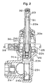
- the electric power steering apparatus 20 is mainly composed of a steering wheel 21, a steering shaft 22, a pinion shaft 23, a rack shaft 24, a torque sensor 30, a motor 40, a motor resolver 44, ball screw mechanism 50, ECU (electronic control unit) 60 and the like.
- the electric power steering apparatus detects the steering state of steering wheel 21, and generates an assisting force corresponding to the steering state by the motor 40 so as to assist the steering operation of a driver.
- Steered wheels (not shown) are connected to both ends of the rack shaft 24 respectively through a tie rod and the like.
- the ECU 60 serves as torsion calculating means and a motor controlling means
- the steering wheel 21 is connected to one end of the steering shaft 22.
- the other end of the steering shaft 22 is connected to one end of a torsion bar 31 and an input shaft 23a of the pinion shaft 23, which is accommodated in a pinion housing 25, by means of a pin 32.
- the other end 31 a of the torsion bar 31 is press fitted into one end of an output shaft 23b of the pinion shaft 23.
- the input shaft 23a and output shaft 23b are rotatably supported by bearings 33a and 33b, respectively.
- a first resolver 35 is provided between the input shaft 23a and the pinion housing 25.
- a second resolver 37 is provided between the output shaft 23b and the pinion housing 25.
- the first resolver 35 and second resolver 37 are capable of detecting a steering angle of the steering wheel 21, and are electrically connected to the ECU 60 (referring to Fig. 5) through a terminal 39 (referring to Fig. 2).
- the other end of the output shaft 23b of the pinion shaft 23 is formed with a pinion gear 23c.
- the pinion gear 23c meshes with a rack tooth 24a of the rack shaft 24 so as to construct a rack and pinion mechanism.
- the steering shaft 22 is connected to the output shaft 23b of the pinion shaft 23 so as to be able to relatively rotate with each other.
- the rotating angle of the steering shaft 22, i.e. rotating angle (mechanical angle) ⁇ m of steering wheel, can be detected on the basis of a first rotating angle (electrical angle) ⁇ e1 by the first resolver 35 and a second rotating angle (electrical angle) ⁇ e2 by the second resolver 37.
- torsion amount of the torsion bar 31 (torsion amount is corresponding to steering torque) can be detected as torsion angle in accordance with an angle difference between first rotating angle ⁇ e1 and second rotating angle ⁇ e2.
- a radial protrusion 23d is provided on the input shaft 23a of the pinion shaft 23.
- a pair of restricting portions 23e and 23e is provided on the top end of the output shaft 23b of the pinion shaft so as to restrict the rotation of the input shaft 23a by contacting the protrusion 23d.
- the contact between the protrusion 23d and the restricting portion 23e limits rotation of the torsion bar 31 with in 12 degrees (6 degree to -6 degree). That is, maximum torsion angle of the torsion bar 31 is limited within 12 degrees.
- the restricting portions 23e and the protrusion 23d serve as restriction means.
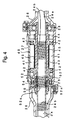
- the rack shaft 24 is accommodated in a rack housing 26 and a motor housing 27.
- a ball groove 24b is spirally formed on the intermediate portion of the rack shaft 24.
- a cylindrical motor shaft 43 which is supported by a bearing 29 so as to rotate coaxially with the rack shaft 24, is provided at outer circumference of the ball groove 24b.
- the motor shaft 43, a stator 41, an exciting coil 42 and the like configure the motor 40. Magnetic field generated by the exciting coil 42 wound on the stator 41 affects permanent magnets 45 disposed on outer periphery of the motor shaft 43 corresponding to a rotor. Thus, the motor shaft 43 can rotate.
- a ball nut 52 is installed in the inner periphery of the motor shaft 43 and formed with spiral ball groove 52a.
- a plurality of balls 54 is interposed between the ball groove 52a of the ball nut 52 and the ball groove 24b of the rack shaft 24 with allowed its rolling motion.
- the ball screw mechanism 50 which can move the rack shaft 24 in the axial direction by the rotation of the motor 43.
- the ball screw mechanism 50 which is composed of the ball groove 24b, ball groove 52a and the like, can convert rotating torque in the forward and reverse directions of the motor 43 into reciprocating force in the axial direction of the rack shaft 24.
- this configuration of the electric power steering apparatus 20 is so called a rack-assist-type power steering apparatus.
- the motor resolver 44 capable of detecting the rotating angle (electrical angle) ⁇ Me of the motor 43 is disposed between the motor shaft 43 of the motor 40 and the motor housing 27.
- the motor resolver 44 is electrically connected to the ECU 60 through a non-illustrated terminal (shown in Fig. 5).
- Fig. 5 shows controlling configuration of the electric power steering apparatus 20 according to this embodiment.
- the ECU 60 outputs excitation signal E1 to the first resolver 35, the second resolver 37 and the motor resolver 44 via a terminal 60a, 60b and 60c, respectively.
- a Sin phase signal from a Sin output terminal 35s of the first resolver 35, a Cos phase signal from a Cos output terminal 35c, a Sin phase signal from a Sin output terminal 37s of the second resolver 37, and a Cos phase signal from a Cos phase terminal 37c are inputted to the ECU 60.
- the ECU 60 calculates a steering torque T, and outputs assist command for assisting the steering operation in accordance with the steering torque T, to a motor drive circuit 62 as described later.
- the motor drive circuit 62 controls the motor 43 so as to generate the torque corresponding to the assist command.
- Rotating angle of the motor 40 is detected by the motor resolver 44.
- a Sin phase signal from Sin output terminal 44s and a Cos phase signal from Cos output terminal 44c are fed back to the motor drive circuit 62 and are inputted to the ECU 60.
- the ECU 60 calculates the steering torque of the steering wheel 21 on the basis of the signals from the first resolver 35, the second resolver 37 and the motor resolver 44, and computes the assist amount in accordance with the steering torque.
- the electrical angel ⁇ e1 obtained from the first resolver 35 has five peak points per single rotation (between mechanical angel 360 degrees) of the steering wheel 21 because the first resolver 35 is a type of pole pair number 5.
- the first resolver 35 of pole pair number 5 has five pairs of N pole and S pole, so that it is capable of outputting electrical angle corresponding to 1800 degrees (360 degrees * 5) with respect to mechanical angel of 360 degrees. That is, the first resolver 35 has fivefold resolution relative to the resolution of the resolver has one pole pair.
- the electrical angel ⁇ e2 obtained from the second resolver 37 has six peak points per single rotation (between mechanical angel 360 degrees) of the steering wheel because the second resolver 37 is a type of pole pair number 6.
- the second resolver 37 of pole pair number 6 has six pairs of N pole and S pole, so that it is capable of outputting electrical angle corresponding to 2160 degrees (360 degrees * 6) with respect to mechanical angle of 360 degrees. That is, the second resolver 37 has sixfold resolution relative to the resolution of the resolver has one pole pair.
- the first and second resolvers output the electrical angles ⁇ e1 and ⁇ e2 as resolver output signals, respectively.
- the electric angels ⁇ e1 and ⁇ e2 that are outputted at same rotating angel of the steering wheel 21 are not correspond with each other. Therefore, the ECU 60 can execute calculating transaction in accordance with the electric angel ⁇ e1 of first resolver 35 and the electrical angle ⁇ e2 of second resolver 37 so as to obtain the mechanical angle ⁇ m having high resolution with respect to single rotation of the steering wheel 21, without using the additional steering angle sensor.
- the first resolver 35 outputs two kinds of alternating voltages E2 and E3 each having a different phase.
- the alternating voltages E2 (the Cos phase signal from Cos output signal) and E3 (the Sin phase signal from Sin output terminal) satisfy the relation following expressions (1) and (2).
- E2 K*E1*Cos ⁇
- E3 K*E1*Sin ⁇
- K means translation ratio.
- the angle ⁇ can be calculated from expressions (1) and (2) by using the value obtained by dividing E3 by E2.
- the angle ⁇ is the electric angle ⁇ e1 of the input shaft 23a of the pinion shaft 23.
- the output shaft 23b which is connected to the input shaft 23a via the torsion bar 31 also rotates.
- the rotating angle ⁇ 2 of the output shaft 23b can be calculated from expressions (1) and (2) from the second resolve 37 by using the value obtained by dividing E3 by E2.
- the resolver is one kind of the electrical transformer, the translation ratio K varies in accordance with temperature variation.
- the Sin phase signal E3 and Cos phase singnal E2 also changes according to temperature variation.
- the angle ⁇ is calculated based on the value obtained by dividing E3 by E2, variation in the translation ratio K is cancelled, so that detecting accuracy is not affected by temperature variation.
- the steering torque T can be calculated on the basis of the rigidity of the torsion bar 31 and the relative rotating angle difference ⁇ corresponding to torsion angle of the torsion bar 31.
- the ECU 60 executes assist control in accordance with the steering torque T so as to assist the steering operation of the driver by the assisting force generated by the motor 40.
- motor rotating angle Detection of the rotating angle (hereinafter reffered to as motor rotating angle) of the motor shaft 43 based on the resolver output signal from the motor resolver 44 will be explained as follows.
- alternating voltage E1 is applied to the motor resolver 44 when the motor shaft 43 rotates at certain rotating angle
- alternating voltages E2 and E3 (the Cos phase signal from the Cos output terminal and the Sin phase signal from the Sin output terminal 44s) are outputted from the motor resolver 44 in accordance with the applied voltage E1 and the rotating angle.
- the motor rotating angle is calculated from the applied alternating voltage E1 and outputted alternating voltages E2 and E3 according to the expressions (1) and (2). This detected motor rotating angle is used for various kinds of controls for the electric power steering apparatus 20.
- the first resolver 35 is a type of pole pair number 5 and the second resolver 37 is a type of pole pair number 6.
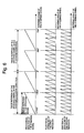
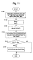
- the ECU 60 obtains the electrical angles ⁇ e1 and ⁇ e2 of the first and second resolvers 35 and 37 (S12). Then, in order that a gradient of the electrical angle ⁇ e1 corresponds to a gradient of the electrical angle ⁇ e2, the electrical angle ⁇ e1 of the first resolver 35 having five pole pairs is multiplied by six and the electrical angle ⁇ e2 of the second resolver 37 having six pole pairs is multiplied by five (S14). These multiplied electrical angles (degree) are shown in Fig. 7. In Fig. 7, a horizontal axis indicates mechanical angle (degree), and vertical axes designate multiplied electrical angles.
- the electrical angle of the first resolver 35 of the pole pair number 5 indicates 0 at every 72 degree of the mechanical angle.
- the electrical angel of the second resolver 37 of the pole pair number 6 indicates 0 at every 60 degree of the mechanical angle.
- the multiplied electrical angle of the first resolver 35 corresponds to the multiplied electrical angle of the second resolver 37. Since the multiplied electrical angle of the second resolver 37 once indicates 0 at 60 degree of mechanical angle, in the range of the mechanical angle 60 degree to 72 degree, the difference of 1800 degrees appears between the multiplied electrical angel of the first resolver 35 and the multiplied electrical angle of the second resolver 37 (area No. 10).
- the multiplied electrical angel of the first resolver 35 once indicates 0 at 72 degree of the mechanical angle, in the range of the mechanical angle 72 degree to 120 degree, the difference of -360 degrees appears between the multiplied electrical angle of the first resolver 35 and the multiplied electrical angle of the second resolver 37 (area No. 4). In the range of the mechanical angle 120 degree to 144 degree (area No. 9), the difference of 1440 degrees appears between the multiplied electrical angle of the first resolver 35 and the multiplied electrical angle of the second resolver 37. in the range of the mechanical angle 144 degree to 180 degree (area No. 3), the difference of -720 degrees appears between the multiplied electrical angle of the first resolver 35 and the multiplied electrical angle of the second resolver 37.
- the difference of -1440 degrees appears between the multiplied electrical angle of the first resolver 35 and the multiplied electrical angle of the second resolver 37.
- the difference of 360 degrees appears between the multiplied electrical angle of the first resolver 35 and the multiplied electrical angle of the second resolver 37.
- the mechanical angle is equal to or more than 360 degree (area No. 11)
- the difference of 160 degrees appears between the multiplied electrical angle of the first resolver 35 and the multiplied electrical angle of the second resolver 37.
- the mechanical angle is less than 0 degree (area No. 0)
- the difference of -1800 degrees appears between the multiplied electrical angle of the first resolver 35 and the multiplied electrical angle of the second resolver 37.
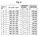
- a compensation value ⁇ for compensating the difference value ⁇ is obtained with reference to a table of areas (S18).
- the table for obtaining the compensation value ⁇ corresponding to the difference value ⁇ is shown in Fig. 8.
- the difference value ⁇ of electrical angle appears within -180 degree to 180 degree, therefore the compensation value ⁇ is equal to 0 degree.
- the difference value ⁇ of the electrical angle appears within the 1620 degree to 1980 degree, therefore the compensation value ⁇ is equal to 1800 degrees.
- a repeated number N1 means the repeated number of the electrical angle of the first resolver 35
- the value, which is obtained by subtracting the compensation value ⁇ from the difference value ⁇ of the electrical angle, is divided by 30 to calculate the torsion angle (mechanical angle) between the first resolver 35 and second resolver 37.
- the calculated torsion angle is multiplied by a spring constant of the torsion bar 31 to obtain the steering torque (S20).
- '30' is used in the calculation because the multiplied electrical angle are obtained by multiplying the electrical angle of the first resorlver 35, whose pole pair number is 5, by 6.
- the torsion angle (mechanical angle) can be obtained from the value which is calculated by subtracting the compensation value B from the difference value ⁇ .
- the maximum torsion angle of the torsion bar 31 is limited within the 12 degrees (-6 degree to +6degree) by the restricting pieces 23e explained above (referring to Fig. 3). Therefore, the calculation of the torsion angle is prevented from including error.
- difference value ⁇ is belong to the area No. 5, therefore the compensation value ⁇ is 0 degree so that the compensated difference value ( ⁇ - ⁇ ) is 180 degrees.
- the difference value ⁇ is included within -1800 degree to 2160 (i.e. with in area No. 0 to No. 11).
- the torsion angle can be adequately detected by restricting the maximum torsion angle of the torsion bar 31 within 12 degrees (+6 degree to -6 degree).
- the resolver of the pole pair number 6 is employed as first resolver 35 and the resolver of the pole pair number 5 is employed as second resolver 37, it is also preferable to restrict the maximum torsion angle of the torsion bar 31 within 12 degrees (+6 degree to -6 degree).
- the pole pair number of one resolver is needed to differ from the pole pair number of the other resolver in order to detect the absolute angle (mechanical angle) without using an additional angle sensor.
- pole pair numbers of the two resolvers If the difference between pole pair numbers of the two resolvers is equeal to or greater than 2, the accuracy and resolution of the detection are deteriorated. Therefore, the following combinations of pole pair numbers are acceptable for actual use under the condition that the pole pair number is not greater than 10. '2 and 3', '3 and 4', '4 and 5', '5 and 6', '6 and 7'; '7 and 8', '8 and 9', and '9 and 10'.
- Fig. 9 (A) shows the relationship between the mechanical angle and electrical angles in case of the combination '3 and 4'.
- the electrical angle of the resolver whose pole pair number is 3 is multiplied by 4
- the electrical angle of the resolver whose pole pair number is 4 is multiplied by 3.
- Fig. 9 (B) shows the relationship between the mechanical angle and electrical angles in case of the combination '4 and 5'.
- the electrical angle of the resolver whose pole pair number is 4 is multiplied by 5
- the electrical angle of the resolver whose pole pair number is 5 is multiplied by 4.
- Fig. 9(C) shows the relationship between the mechanical angle and electrical angles in case of the combination '5 and 6'.
- the compensation value ⁇ is 0 degree in an area No. 1.
- the graph shows same characteristic as the area No. 1.
- the mechanical angle of the resolver of the pole pair number 4 is rotated in opposite direction. Therefore, relative rotation between two resolvers is need to be restricted within 30 degrees (+15 degree to -15 degree).
- each of 'n' and 'm' denotes the pole pair number, and satisfies the relation 'm ⁇ n'.
- the maximum torsion angle corresponding to the combination of the pole pair numbers is as follows.
- the maximum torsion angle is 60 degrees (+30 degree to -30 degree).
- the maximum torsion angle is 30 degrees (+15 degree to -15 degree).
- the maximum torsion angle is 18 degrees (+9 degree to -9 degree).
- the maximum torsion angle is 12 degrees (+6 degree to -6 degree).
- the maximum torsion angle is 8.6 degrees (+4.3 degree to - 4.3 degree).
- the maximum torsion angle is 6.4 degrees (+3.2 degree to - 3.2 degree).
- the maximum torsion angle is 5 degrees (+2.5 degree to -2.5 degree).
- the maximum torsion angle is 4 degrees (+2 degree to -2 degree).
- the number 'm' of pole pairs of the first resolver is set at 5
- the number 'n' of pole pairs of the second resolver is set at 6
- the maximum torsion angle of the torsion bar is set at 12 degrees (+6 degree to -6 degree). Therefore, in the configuration for detecting the steering torque with torsion bar, the steering torque can be detected with high accuracy.
- the difference between pole pair numbers of the two resolvers is equeal to or greater than 2
- the accuracy and resolution of the detection are deteriorated.
- the combination of pole pair numbers is '3 and 4', resolution of the detection is deteriorated.
- the maximum torsion angle of the torsion bar becomes too small relative to the maximum torsion angle at the combination '5 and 6' as described above, so that the accuracy of the detection is deteriorated.
- the restricting piece 23e and protrusion 23d serving as restricting means limit the maximum angle of the torsion bar 31.
- the ECU 60 judges whether the angle difference between the rotating angle detected by the first resolver 35 and the rotating angle detected by the second resolver 37 exceeds the maximum torsion angle of the torsion bar 31. When the difference exceeds the maximum torsion angle, it is judged that the malfunction occurs. In case that the difference exceeds maximum torsion angle limited by the restricting piece 23e and the protrusion 23d for the torsion bar 31, that is, in case that the difference which must not occur is detected, it is judged that the malfunction arises. Thus, the malfunction is detected in a short period of time.
- the above embodiment has been described as the electric power steering apparatus 20 of the rack-assist-type power steering apparatus.
- present invention can be applied for a pinion-assist-type power steering apparatus, a column-assist-type power steering apparatus or the like. In such cases, the same effects as those in the above embodiment are obtained.
- An electric power steering apparatus includes a first resolver whose pole pair number is 'm' and a second resolver whose pole pair'n'.
- the electric power steering apparatus further includes a torsion calculating means which calculates the a torsion angle of the torsion bar from a difference between the rotating angle detected by the first resolver and the rotating angle detected by the second resolver.
- the torsion calculating means compensates the angle difference by a compensation value obtained by a table on the basis of the value obtained by multiplying an electrical angel of the first resolver by'n' and the value obtained by multiplying an electrical angle of the second resolver by 'm'.
Landscapes
- Engineering & Computer Science (AREA)
- Physics & Mathematics (AREA)
- General Physics & Mathematics (AREA)
- Chemical & Material Sciences (AREA)
- Combustion & Propulsion (AREA)
- Transportation (AREA)
- Mechanical Engineering (AREA)
- Electromagnetism (AREA)
- Power Steering Mechanism (AREA)
- Steering Control In Accordance With Driving Conditions (AREA)
- Measurement Of Length, Angles, Or The Like Using Electric Or Magnetic Means (AREA)
Applications Claiming Priority (2)
| Application Number | Priority Date | Filing Date | Title |
|---|---|---|---|
| JP2003326059 | 2003-09-18 | ||
| JP2003326059A JP2005091204A (ja) | 2003-09-18 | 2003-09-18 | 電気式動力舵取装置 |
Publications (2)
| Publication Number | Publication Date |
|---|---|
| EP1516799A1 true EP1516799A1 (fr) | 2005-03-23 |
| EP1516799B1 EP1516799B1 (fr) | 2006-11-02 |
Family
ID=34191344
Family Applications (1)
| Application Number | Title | Priority Date | Filing Date |
|---|---|---|---|
| EP04022072A Active EP1516799B1 (fr) | 2003-09-18 | 2004-09-16 | Direction assistée électrique et procédé pour compenser l'angle correspondant |
Country Status (4)
| Country | Link |
|---|---|
| US (1) | US7076352B2 (fr) |
| EP (1) | EP1516799B1 (fr) |
| JP (1) | JP2005091204A (fr) |
| DE (1) | DE602004003005T2 (fr) |
Cited By (3)
| Publication number | Priority date | Publication date | Assignee | Title |
|---|---|---|---|---|
| EP2802505B1 (fr) * | 2012-01-10 | 2017-03-15 | Tedrive Steering Systems GmbH | Ensemble de direction assistée comprenant un système de détection de position angulaire |
| CN108248677A (zh) * | 2016-12-28 | 2018-07-06 | 株式会社捷太格特 | 车辆用转向操纵装置 |
| CN110641547A (zh) * | 2018-06-26 | 2020-01-03 | 丰田自动车株式会社 | 车辆用转向系统 |
Families Citing this family (16)
| Publication number | Priority date | Publication date | Assignee | Title |
|---|---|---|---|---|
| US6983817B2 (en) * | 2003-03-18 | 2006-01-10 | Toyoda Koki Kabushiki Kaisha | Power steering device |
| EP1462786B1 (fr) * | 2003-03-27 | 2007-01-31 | Jtekt Corporation | Capteur de couple et direction assistée électrique utilisant ce capteur |
| JP4042049B2 (ja) * | 2003-04-16 | 2008-02-06 | 株式会社ジェイテクト | 電動パワーステアリング装置の操舵角検出装置 |
| JP2005219573A (ja) * | 2004-02-04 | 2005-08-18 | Denso Corp | 車両の電動パワーステアリング制御装置 |
| US20090007697A1 (en) * | 2004-08-02 | 2009-01-08 | Lutz May | Sensor Device Capable of Identifying any Components of a Mechanical Force Applied to a Movable Object |
| JP2006062535A (ja) * | 2004-08-27 | 2006-03-09 | Showa Corp | 電動舵取補助装置 |
| JP5369527B2 (ja) * | 2008-07-29 | 2013-12-18 | 株式会社ジェイテクト | 舵角検出装置 |
| US8428822B2 (en) | 2009-03-13 | 2013-04-23 | Honda Motor Co., Ltd. | Method of determining a steering angle in a motor vehicle |
| US8615882B2 (en) * | 2009-07-22 | 2013-12-31 | Arthur Sisson | Method of manufacturing a power assisted steering control assembly |
| JP5712724B2 (ja) * | 2011-02-15 | 2015-05-07 | 株式会社ジェイテクト | トルク検出装置および電動パワーステアリング装置 |
| JP5953955B2 (ja) * | 2012-06-07 | 2016-07-20 | 株式会社ジェイテクト | トルクセンサ |
| KR101524732B1 (ko) * | 2012-08-16 | 2015-05-29 | 주식회사 만도 | 전동식 파워 스티어링 시스템 및 그의 조향각 출력 방법 |
| CN102789242A (zh) * | 2012-09-03 | 2012-11-21 | 中国科学院国家天文台南京天文光学技术研究所 | 实现天文望远镜扭转角非线性干扰补偿的控制系统 |
| JP6345386B2 (ja) | 2012-12-13 | 2018-06-20 | ミネベアミツミ株式会社 | 回転角検出装置 |
| CN105793139B (zh) * | 2014-03-05 | 2018-11-30 | 日本精工株式会社 | 电动式助力转向装置及其组装方法 |
| CN105829190B (zh) * | 2014-03-05 | 2018-03-16 | 日本精工株式会社 | 电动式助力转向装置及其组装方法 |
Citations (1)
| Publication number | Priority date | Publication date | Assignee | Title |
|---|---|---|---|---|
| EP1344711A2 (fr) * | 2002-03-13 | 2003-09-17 | Koyo Seiko Co., Ltd. | Appareils pour détecter un angle de rotation, un couple et un mécanisme de direction |
Family Cites Families (11)
| Publication number | Priority date | Publication date | Assignee | Title |
|---|---|---|---|---|
| JPS61119468A (ja) * | 1984-11-16 | 1986-06-06 | Honda Motor Co Ltd | 電動式パワ−ステアリング装置 |
| US5198981A (en) * | 1990-10-09 | 1993-03-30 | General Motors Corporation | Closed-loop torque control for electric power steering |
| US5646496A (en) * | 1994-11-08 | 1997-07-08 | Dana Corporation | Apparatus and method for generating digital position signals for a rotatable shaft |
| JP3136937B2 (ja) | 1995-02-06 | 2001-02-19 | トヨタ自動車株式会社 | レゾルバの断線検出方法及び装置 |
| JP3588499B2 (ja) | 1995-04-13 | 2004-11-10 | 多摩川精機株式会社 | 巻線型回転検出器の故障検出方法及び装置 |
| JP3725694B2 (ja) | 1998-05-20 | 2005-12-14 | 光洋精工株式会社 | 車両のステアリング装置 |
| US20020124663A1 (en) * | 1999-04-07 | 2002-09-12 | Yoshitomo Tokumoto | Rotational angle detecting device, torque detecting device and steering apparatus |
| US6525502B1 (en) * | 1999-09-02 | 2003-02-25 | Aspen Motion Technologies, Inc. | Closed loop control of motor position and velocity |
| JP3784248B2 (ja) * | 2000-10-02 | 2006-06-07 | 株式会社ジェイテクト | 回転角度検出装置、トルクセンサ及び舵取装置 |
| DE60223898T2 (de) * | 2002-01-30 | 2008-11-27 | Continental Automotive Gmbh | Verfahren und Vorrichtung zur Ermittlung der Läuferstellung eines Motors durch das Einspeisen eines Resolversignals, das aus der Läuferstellung abgeleitet wird, in ein einziges Steuerungssystem, das sowohl zum Auslösen als auch zum Bestimmen des Resolversignals dient, und ein motorisiertes Fahrzeug, das mit einer solchen Vorrichtung ausgestattet ist |
| JP3969220B2 (ja) | 2002-07-04 | 2007-09-05 | 株式会社ジェイテクト | 電動パワーステアリング装置の絶対位置検出装置及び絶対位置検出方法 |
-
2003
- 2003-09-18 JP JP2003326059A patent/JP2005091204A/ja active Pending
-
2004
- 2004-09-16 DE DE602004003005T patent/DE602004003005T2/de active Active
- 2004-09-16 EP EP04022072A patent/EP1516799B1/fr active Active
- 2004-09-17 US US10/942,878 patent/US7076352B2/en active Active
Patent Citations (1)
| Publication number | Priority date | Publication date | Assignee | Title |
|---|---|---|---|---|
| EP1344711A2 (fr) * | 2002-03-13 | 2003-09-17 | Koyo Seiko Co., Ltd. | Appareils pour détecter un angle de rotation, un couple et un mécanisme de direction |
Cited By (4)
| Publication number | Priority date | Publication date | Assignee | Title |
|---|---|---|---|---|
| EP2802505B1 (fr) * | 2012-01-10 | 2017-03-15 | Tedrive Steering Systems GmbH | Ensemble de direction assistée comprenant un système de détection de position angulaire |
| CN108248677A (zh) * | 2016-12-28 | 2018-07-06 | 株式会社捷太格特 | 车辆用转向操纵装置 |
| CN110641547A (zh) * | 2018-06-26 | 2020-01-03 | 丰田自动车株式会社 | 车辆用转向系统 |
| CN110641547B (zh) * | 2018-06-26 | 2022-07-01 | 丰田自动车株式会社 | 车辆用转向系统 |
Also Published As
| Publication number | Publication date |
|---|---|
| US20050065686A1 (en) | 2005-03-24 |
| DE602004003005D1 (de) | 2006-12-14 |
| DE602004003005T2 (de) | 2007-05-16 |
| JP2005091204A (ja) | 2005-04-07 |
| US7076352B2 (en) | 2006-07-11 |
| EP1516799B1 (fr) | 2006-11-02 |
Similar Documents
| Publication | Publication Date | Title |
|---|---|---|
| EP1516799A1 (fr) | Direction assistée électrique et procédé pour compenser l'angle correspondant | |
| US6901816B2 (en) | Apparatus and method for detecting absolute position using difference between detection signals of two detectors | |
| US20100045227A1 (en) | Abnormality detection unit for resolver and electric power steering apparatus | |
| US6929089B2 (en) | Electrically driven steering apparatus | |
| US7325646B2 (en) | Electric power steering apparatus | |
| US6536293B2 (en) | Rotational angle detecting apparatus, torque sensor and steering apparatus | |
| EP2243685B1 (fr) | Système d'assistance électrique de direction | |
| CN108698640B (zh) | 电动助力转向设备及用于减小其扭矩波动的方法 | |
| US20060208690A1 (en) | Controller for brushless motor | |
| EP1666837A1 (fr) | Capteur d'angle de braquage | |
| EP1550839A1 (fr) | Detecteur d'angle de braquage absolu et procede de detection de l'angle de braquage absolu pour dispositif de direction assistee electrique | |
| US20050016789A1 (en) | Electric power steering device and method and apparatus for manufacturing the same | |
| JP3964414B2 (ja) | 磁歪式トルクセンサと電動ステアリング装置 | |
| EP1586864B1 (fr) | Dispositif de mesure de l'angle de rotation et direction assistée electrique | |
| US7146287B2 (en) | Resolver signal processing method and processing apparatus | |
| EP1918174A1 (fr) | Système de direction fonctionnant à l'énergie électrique | |
| US6959781B2 (en) | Rotational torque detection mechanism and power steering apparatus | |
| US20030192735A1 (en) | Electric power steering apparatus | |
| US6912921B2 (en) | Torque detecting device | |
| JP4438386B2 (ja) | トルク検出装置 | |
| JP2005098781A (ja) | トルクセンサの故障検出方法、トルクセンサの故障検出装置 | |
| JP2007155641A (ja) | レゾルバ装置及びそれを用いたトルクセンサ | |
| KR100738444B1 (ko) | 전동식 파워 스티어링 시스템의 토크센서 | |
| JP2005219652A (ja) | 電動パワーステアリング装置 |
Legal Events
| Date | Code | Title | Description |
|---|---|---|---|
| PUAI | Public reference made under article 153(3) epc to a published international application that has entered the european phase |
Free format text: ORIGINAL CODE: 0009012 |
|
| AK | Designated contracting states |
Kind code of ref document: A1 Designated state(s): AT BE BG CH CY CZ DE DK EE ES FI FR GB GR HU IE IT LI LU MC NL PL PT RO SE SI SK TR |
|
| AX | Request for extension of the european patent |
Extension state: AL HR LT LV MK |
|
| 17P | Request for examination filed |
Effective date: 20050922 |
|
| AKX | Designation fees paid |
Designated state(s): DE FR GB |
|
| GRAP | Despatch of communication of intention to grant a patent |
Free format text: ORIGINAL CODE: EPIDOSNIGR1 |
|
| GRAS | Grant fee paid |
Free format text: ORIGINAL CODE: EPIDOSNIGR3 |
|
| GRAA | (expected) grant |
Free format text: ORIGINAL CODE: 0009210 |
|
| RAP1 | Party data changed (applicant data changed or rights of an application transferred) |
Owner name: JTEKT CORPORATION |
|
| AK | Designated contracting states |
Kind code of ref document: B1 Designated state(s): DE FR GB |
|
| REG | Reference to a national code |
Ref country code: GB Ref legal event code: FG4D |
|
| RIN2 | Information on inventor provided after grant (corrected) |
Inventor name: ASADA, ATSUHISAJTEKT CORPORATION Inventor name: KOHNO, TOSHIOJTEKT CORPORATION |
|
| REF | Corresponds to: |
Ref document number: 602004003005 Country of ref document: DE Date of ref document: 20061214 Kind code of ref document: P |
|
| ET | Fr: translation filed | ||
| PLBE | No opposition filed within time limit |
Free format text: ORIGINAL CODE: 0009261 |
|
| STAA | Information on the status of an ep patent application or granted ep patent |
Free format text: STATUS: NO OPPOSITION FILED WITHIN TIME LIMIT |
|
| 26N | No opposition filed |
Effective date: 20070803 |
|
| PGFP | Annual fee paid to national office [announced via postgrant information from national office to epo] |
Ref country code: GB Payment date: 20080917 Year of fee payment: 5 |
|
| GBPC | Gb: european patent ceased through non-payment of renewal fee |
Effective date: 20090916 |
|
| PG25 | Lapsed in a contracting state [announced via postgrant information from national office to epo] |
Ref country code: GB Free format text: LAPSE BECAUSE OF NON-PAYMENT OF DUE FEES Effective date: 20090916 |
|
| REG | Reference to a national code |
Ref country code: FR Ref legal event code: PLFP Year of fee payment: 13 |
|
| REG | Reference to a national code |
Ref country code: FR Ref legal event code: PLFP Year of fee payment: 14 |
|
| REG | Reference to a national code |
Ref country code: FR Ref legal event code: PLFP Year of fee payment: 15 |
|
| PGFP | Annual fee paid to national office [announced via postgrant information from national office to epo] |
Ref country code: FR Payment date: 20230808 Year of fee payment: 20 Ref country code: DE Payment date: 20230802 Year of fee payment: 20 |