EP1516778A2 - Convoyeur - Google Patents
Convoyeur Download PDFInfo
- Publication number
- EP1516778A2 EP1516778A2 EP04255542A EP04255542A EP1516778A2 EP 1516778 A2 EP1516778 A2 EP 1516778A2 EP 04255542 A EP04255542 A EP 04255542A EP 04255542 A EP04255542 A EP 04255542A EP 1516778 A2 EP1516778 A2 EP 1516778A2
- Authority
- EP
- European Patent Office
- Prior art keywords
- chain
- conveyor
- rail
- airbag
- housing
- Prior art date
- Legal status (The legal status is an assumption and is not a legal conclusion. Google has not performed a legal analysis and makes no representation as to the accuracy of the status listed.)
- Withdrawn
Links
Images


Classifications
-
- B—PERFORMING OPERATIONS; TRANSPORTING
- B65—CONVEYING; PACKING; STORING; HANDLING THIN OR FILAMENTARY MATERIAL
- B65G—TRANSPORT OR STORAGE DEVICES, e.g. CONVEYORS FOR LOADING OR TIPPING, SHOP CONVEYOR SYSTEMS OR PNEUMATIC TUBE CONVEYORS
- B65G17/00—Conveyors having an endless traction element, e.g. a chain, transmitting movement to a continuous or substantially-continuous load-carrying surface or to a series of individual load-carriers; Endless-chain conveyors in which the chains form the load-carrying surface
- B65G17/002—Conveyors having an endless traction element, e.g. a chain, transmitting movement to a continuous or substantially-continuous load-carrying surface or to a series of individual load-carriers; Endless-chain conveyors in which the chains form the load-carrying surface comprising load carriers resting on the traction element
-
- B—PERFORMING OPERATIONS; TRANSPORTING
- B65—CONVEYING; PACKING; STORING; HANDLING THIN OR FILAMENTARY MATERIAL
- B65G—TRANSPORT OR STORAGE DEVICES, e.g. CONVEYORS FOR LOADING OR TIPPING, SHOP CONVEYOR SYSTEMS OR PNEUMATIC TUBE CONVEYORS
- B65G47/00—Article or material-handling devices associated with conveyors; Methods employing such devices
- B65G47/22—Devices influencing the relative position or the attitude of articles during transit by conveyors
- B65G47/26—Devices influencing the relative position or the attitude of articles during transit by conveyors arranging the articles, e.g. varying spacing between individual articles
- B65G47/261—Accumulating articles
-
- B—PERFORMING OPERATIONS; TRANSPORTING
- B65—CONVEYING; PACKING; STORING; HANDLING THIN OR FILAMENTARY MATERIAL
- B65G—TRANSPORT OR STORAGE DEVICES, e.g. CONVEYORS FOR LOADING OR TIPPING, SHOP CONVEYOR SYSTEMS OR PNEUMATIC TUBE CONVEYORS
- B65G67/00—Loading or unloading vehicles
- B65G67/02—Loading or unloading land vehicles
- B65G67/04—Loading land vehicles
- B65G67/20—Loading covered vehicles
Definitions
- This invention relates to a conveyor system, and in particular to an accumulating conveyor for use inside a vehicle.
- an accumulating conveyor is used, so that pallets can be fed into the trailer in succession so that, when a given pallet is fed into the trailer as far as it can travel, that pallet will maintain its position whilst the conveyor continues to feed further pallets into the trailer.
- an accumulating conveyor has one or more endless chains, the links of which carry freely-rotatable rollers.
- a known conveyor system of this type has a central drive chain and a pair of sets of rollers positioned on opposite sides thereof.
- the central chain is positioned within an elongate recessed portion of the trailer floor, and each of the sets of rollers is similarly positioned in a respective elongate recessed portion of the trailer floor, the three recessed portions extending longitudinally along the floor of the trailer.
- a respective airbag is positioned on the base of each of the recessed portions, so that the airbags can support the sets of rollers and the drive chain. In use, the airbags are inflated to lift the drive chain and the rollers slightly above the trailer floor. Pallets can then be fed into the trailer by engaging the drive of the chain.
- the airbags are deflated, and the pallets drop down to rest on the floor of the trailer. Frictional contact between the pallets and the trailer floor will subsequently tend to prevent movement of the pallets relative to the floor as the trailer moves, particularly when it accelerates or is braked.
- the present invention provides a conveyor system for loading pallets into and out of a vehicle, the system comprising an accumulating conveyor and an airbag rail, the accumulating conveyor being constituted by a pair of chain rails for supporting and conveying pallets into and out of a vehicle, the airbag rail being positioned between the chain rails and adjacent to one of the chain rails, wherein the airbag rail is constituted by a base beam, a lift beam and an airbag positioned between the two beams, the arrangement being such that, with the chain rails and the base beam fixed to the floor of a vehicle, the airbag can be inflated to raise the lift beam so as to lift an edge portion of a pallet supported by the two chain rails out of contact with said one chain rail.
- each chain rail comprises a chain rail housing and an endless conveyor chain, the housing defining an upper surface which supports a working run of the conveyor chain, the interior of the housing surrounding a return run of the conveyor chain.
- each conveyor chain has a plurality of links, each of which supports a freely-rotatable roller, and the links of the conveyor chains are provided with wear strips for contact with the upper surface of the associated chain rail housing.
- each chain rail housing and the base beam are provided with means for fixing to a vehicle floor.
- each chain rail housing is provided with an upwardly-projecting flange at that side thereof remote from the other chain rail housing.
- the upwardly-projecting flange of the housing of said one chain rail may be provided with an inwardly-extending lip at the upper end thereof.
- a layer of high friction material is provided on the upper surface of the lift beam.
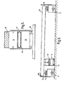
- Figures 1 and 2 show a trailer 1 of an articulated lorry, the trailer containing an accumulating conveyor, indicated generally by the reference numeral 2, which is mounted on the floor of the trailer.
- the conveyor 2 is provided with a drive drum 3 at its front end (the end adjacent to the front of the trailer 1).
- the conveyor 2 is constituted by a pair of chain rails 4 and 5 and an airbag rail 6.
- Each of the chain rails 4, 5 is constituted by an endless, three-quarter inch triplex chain 7 whose links 8 each carry a roller 9, the rollers being freely rotatable with respect to their links.
- the working run 7a of each chain rail 4, 5 is supported above the top surface of a respective chain rail housing 10 by means of chain wear strips 11 made of polyethylene.
- the return run 7b of each chain rail 4, 5 is housed within a respective aluminium extrusion 10a positioned within the housing 10.
- the housings 10 are fixed to the floor of the trailer 1.
- a respective vertical side guide 12 is attached to each of the chain rail housings 10, the side guides being positioned at the extreme lateral edges of the conveyor 2.
- the airbag rail 6 (see Figure 5), which extends the entire length of the conveyor 2, has a base beam 13 fixed to the floor of the trailer 1 by means of a pillar 14.
- the base beam 13 supports a lift beam 15, an airbag 16 being positioned between the two beams.
- the lift beam 15 is fixed to a housing 17 which slidably engages the side walls of the base beam 13.
- the housing 17 is provided with in-turned lips 18 for limiting movement of the lift beam 15 with respect to the base beam 13, in the manner described below.
- the top surface of the lift beam 15 is provided with a layer 19 made of a material having a high coefficient of friction.
- the layer 19 can, for example, be made of wood or rubber.
- the conveyor 2 is used to move pallets into, and out of, the trailer 1.
- pallets are delivered to the conveyor 2 from a land-based conveyor (not shown).
- This land-based conveyor could be a standard floor mounted conveyor provided in a factory.
- Such a floor mounted conveyor has a dedicated control system for controlling operation of that conveyor, and this control system can be modified to control the conveyor 2 via an umbilical connection (not shown).
- the trailer 1 will be positioned so that the conveyor 2 is adjacent to, and in alignment with, the delivery end of the floor mounted conveyor.
- Pallets 21, each of which supports one or more components such as a car seat, are then fed onto the conveyor 2 from the floor mounted conveyor, both conveyors being set in motion using the control system associated with the floor mounted conveyor.
- the first pallet 21 reaches the front of the trailer 1, it is halted by engagement with the front of the trailer, and the rollers 9 supporting that pallet rotate backwards as the chains 7 move forwards.
- subsequent pallets 21 come to a halt as their front edges engage the rear edge of the pallet immediately in front.
- the airbag rail 6 is operated by inflating the airbag 16 with air from the vehicle's supply.
- An air flow control valve (not shown) is controlled, via the umbilical connection, by the control system. Inflation of the airbag 16 raises one edge of each of the pallets 21 away from the chain rail 5, so that the pallets are supported on the layer 19 on the top surface of the lift beam 15, this layer having a sufficiently high coefficient of friction to inhibit pallet movement when the trailer 1 is accelerated, braked or driven over bumpy roads.
- the pallets 21 can be unloaded by reversing the loading operations described above.
- the rear of the trailer 1 is aligned with a floor mounted conveyor at the destination, the umbilical connection of the floor mounted conveyor is attached to the conveyor 2, air is released from the airbag 16, so that the pallets rest on both chain rails 4 and 5, and the two conveyors are then started, with the chains 7 moving in the opposite direction to that in which they moved during the loading process.
- the pallets 21 are then fed off the conveyor 2 from the rear of the trailer 1 and onto the floor mounted conveyor.
- FIG. 6 shows a conveyor which is a modified version of the conveyor 2 described above. Accordingly, like reference numerals will be used for like parts. In fact, the only difference between this conveyor and that described earlier is that the vertical side guide 12 which is fixed to the chain rail housing 10 of the chain rail 4 is provided with an in-turned flange 12a.
- the conveyor of Figure 6 operates in exactly the same way as that described above with reference to Figures 1 to 5 in the manner in which pallets 21 are loaded and unloaded.
- actuation of the airbag rail 6 by inflating the airbag 16 is effective to lift the pallets 21 against the underneath side of the flange 12a, thereby clamping the pallets between the layer 19 of the lift beam 15 and the underneath surface of the flange. Consequently, if the pallets 21 and their supported loads are light, there is a substantially increased resistance to movement of the pallets when the trailer 1 moves suddenly, for example during hard braking, rapid acceleration or travelling over a particularly bumpy road.
- each of the conveyors described above does not require an air supply to the airbag rail 6 during loading or unloading of pallets, thereby obviating the need for the trailer 1 to be connected to its tractor unit or to a separate air supply during loading or unloading operations.
Landscapes
- Engineering & Computer Science (AREA)
- Mechanical Engineering (AREA)
- Aviation & Aerospace Engineering (AREA)
- Loading Or Unloading Of Vehicles (AREA)
- Automobile Manufacture Line, Endless Track Vehicle, Trailer (AREA)
Applications Claiming Priority (2)
| Application Number | Priority Date | Filing Date | Title |
|---|---|---|---|
| GB0321989A GB2406084B (en) | 2003-09-19 | 2003-09-19 | Conveyor system |
| GB0321989 | 2003-09-19 |
Publications (2)
| Publication Number | Publication Date |
|---|---|
| EP1516778A2 true EP1516778A2 (fr) | 2005-03-23 |
| EP1516778A3 EP1516778A3 (fr) | 2006-04-12 |
Family
ID=29266304
Family Applications (1)
| Application Number | Title | Priority Date | Filing Date |
|---|---|---|---|
| EP04255542A Withdrawn EP1516778A3 (fr) | 2003-09-19 | 2004-09-13 | Convoyeur |
Country Status (3)
| Country | Link |
|---|---|
| US (1) | US6966416B2 (fr) |
| EP (1) | EP1516778A3 (fr) |
| GB (1) | GB2406084B (fr) |
Families Citing this family (14)
| Publication number | Priority date | Publication date | Assignee | Title |
|---|---|---|---|---|
| US7588134B2 (en) * | 2007-07-19 | 2009-09-15 | Alcan International Limited | Deformable/inflatable wear liner |
| US8408384B2 (en) * | 2011-08-25 | 2013-04-02 | Unique Metal Designs, Inc. | Conveyor assembly with selectively movable zones |
| JP5941262B2 (ja) * | 2011-10-31 | 2016-06-29 | 三井住友建設株式会社 | 荷積み物の積み込み取り降ろし装置及び該装置を使用しての荷積み物積み込み取り降ろし方法 |
| CN104192473B (zh) * | 2014-08-27 | 2017-03-15 | 王永昌 | 一种道路系统 |
| US9567166B2 (en) * | 2014-10-10 | 2017-02-14 | Goodrich Corporation | Compact centrifugal air blowers for air cushion supported cargo loading platform |
| US9511860B2 (en) * | 2014-10-10 | 2016-12-06 | Goodrich Corporation | Air cushion aircraft cargo loading systems and wireless communication unit |
| US9555888B2 (en) * | 2014-10-10 | 2017-01-31 | Goodrich Corporation | Pressure compensating air curtain for air cushion supported cargo loading platform |
| US10196146B2 (en) | 2014-10-10 | 2019-02-05 | Goodrich Corporation | Self propelled air cushion supported aircraft cargo loading systems and methods |
| US9511861B2 (en) * | 2014-10-10 | 2016-12-06 | Goodrich Corporation | Noise reduction barrier for air cushion supported aircraft cargo loading robot |
| US10393225B2 (en) | 2015-01-05 | 2019-08-27 | Goodrich Corporation | Integrated multi-function propulsion belt for air cushion supported aircraft cargo loading robot |
| CN105346426A (zh) * | 2015-11-10 | 2016-02-24 | 王东文 | 导轨 |
| CN109129504B (zh) * | 2018-09-06 | 2021-05-18 | 大连理工大学 | 一种气动顶撑救灾机器人 |
| US11813971B2 (en) * | 2021-04-15 | 2023-11-14 | Trout River Industries Inc. | Trailer-mounted conveyor system and method |
| CN113602521B (zh) * | 2021-07-27 | 2023-06-23 | 中航西安飞机工业集团股份有限公司 | 一种超长飞机地板安装装置及安装方法 |
Family Cites Families (12)
| Publication number | Priority date | Publication date | Assignee | Title |
|---|---|---|---|---|
| US3934707A (en) * | 1974-04-24 | 1976-01-27 | Rapistan Incorporated | Belt accumulators |
| GB2126189B (en) * | 1982-08-27 | 1985-11-06 | Package Control Ltd | Load transporting apparatus |
| GB2152895B (en) * | 1984-01-06 | 1987-03-04 | Hydraroll Ltd | Mechanical handling apparatus |
| US4759676A (en) * | 1984-08-31 | 1988-07-26 | Hammond Theodore A | Wheeled vehicle conveying system |
| GB2182907B (en) * | 1985-11-18 | 1989-10-04 | Hydraroll Ltd | Mechanical handling apparatus |
| AU1857488A (en) * | 1987-07-01 | 1989-01-05 | Daniel Gabriel Van Niekerk | Load handling system |
| JPH06508812A (ja) * | 1991-07-03 | 1994-10-06 | ウエスタン アトラス インコーポレイテッド | 無圧力集積コンベヤ |
| US5409096A (en) * | 1992-10-29 | 1995-04-25 | Tekno, Inc. | Lift stop |
| US5350048A (en) * | 1993-04-02 | 1994-09-27 | Wylie John F | Modular component system for assembly of material flow rails |
| AU2001241509A1 (en) * | 2000-02-28 | 2001-09-12 | Morgan Corporation | Roller conveying apparatus |
| US6435328B1 (en) * | 2001-08-03 | 2002-08-20 | Theodore A. Hammond | Gravity-advance conveyor for pallet loads |
| US6746199B2 (en) * | 2001-10-16 | 2004-06-08 | Paul Jennings Carawan | Adjustable system and method for facilitating handling of cargo |
-
2003
- 2003-09-19 GB GB0321989A patent/GB2406084B/en not_active Expired - Fee Related
-
2004
- 2004-09-13 EP EP04255542A patent/EP1516778A3/fr not_active Withdrawn
- 2004-09-14 US US10/940,341 patent/US6966416B2/en not_active Expired - Fee Related
Also Published As
| Publication number | Publication date |
|---|---|
| GB0321989D0 (en) | 2003-10-22 |
| EP1516778A3 (fr) | 2006-04-12 |
| GB2406084A (en) | 2005-03-23 |
| GB2406084B (en) | 2006-12-27 |
| US20050063809A1 (en) | 2005-03-24 |
| US6966416B2 (en) | 2005-11-22 |
Similar Documents
| Publication | Publication Date | Title |
|---|---|---|
| US6966416B2 (en) | Conveyor system | |
| US11440752B2 (en) | Vehicle loading system | |
| CA1102752A (fr) | Traduction non-disponible | |
| CN107826786B (zh) | 物流设备 | |
| NL8700453A (nl) | Laadvloer van een vrachtvoertuig. | |
| US3931897A (en) | Load-out conveyor apparatus | |
| US4261682A (en) | Loading and unloading of vehicles | |
| CN109368296B (zh) | 一种物料上车系统 | |
| US10472177B2 (en) | Extruded chain rail for loading system | |
| US6368042B1 (en) | Vehicle loading and unloading system | |
| AU2054899A (en) | Loading and unloading system for cargo trucks, their trailers, transport containers and the like | |
| KR101470042B1 (ko) | 벌크재용 저장 화차 | |
| CN1874942A (zh) | 物料搬运系统 | |
| US5664663A (en) | Reciprocating floor conveyor | |
| NL8602846A (nl) | Laadvloer en een van een dergelijk laadvloer voorzien voertuig. | |
| NL1008184C2 (nl) | Transportsysteem. | |
| NL2023603B1 (nl) | Beladingsmodule en werkwijze voor transport van goederen | |
| EP1028085A2 (fr) | System zum Beladen und Entladen eines Fahrzeugs | |
| CN110214119B (zh) | 传送系统 | |
| EP2353932B1 (fr) | Véhicule de transport doté d'une plateforme de chargement mobile | |
| GB2309448A (en) | Vehicle with loading/unloading apparatus | |
| JP5448570B2 (ja) | 搬送装置 | |
| WO1986001492A1 (fr) | Convoyeur alternatif a profil bas actionne par un fluide | |
| JP2001039208A (ja) | 貨物自動車の積荷の搬入、搬出装置 | |
| JPH0659940B2 (ja) | 荷移載装置 |
Legal Events
| Date | Code | Title | Description |
|---|---|---|---|
| PUAI | Public reference made under article 153(3) epc to a published international application that has entered the european phase |
Free format text: ORIGINAL CODE: 0009012 |
|
| AK | Designated contracting states |
Kind code of ref document: A2 Designated state(s): AT BE BG CH CY CZ DE DK EE ES FI FR GB GR HU IE IT LI LU MC NL PL PT RO SE SI SK TR |
|
| AX | Request for extension of the european patent |
Extension state: AL HR LT LV MK |
|
| PUAL | Search report despatched |
Free format text: ORIGINAL CODE: 0009013 |
|
| AK | Designated contracting states |
Kind code of ref document: A3 Designated state(s): AT BE BG CH CY CZ DE DK EE ES FI FR GB GR HU IE IT LI LU MC NL PL PT RO SE SI SK TR |
|
| AX | Request for extension of the european patent |
Extension state: AL HR LT LV MK |
|
| RIC1 | Information provided on ipc code assigned before grant |
Ipc: B65G 47/26 20060101ALI20060223BHEP Ipc: B65G 47/29 20060101ALI20060223BHEP Ipc: B65G 47/88 20060101ALI20060223BHEP Ipc: B60P 1/38 20060101AFI20060223BHEP |
|
| 17P | Request for examination filed |
Effective date: 20060911 |
|
| 17Q | First examination report despatched |
Effective date: 20061102 |
|
| AKX | Designation fees paid |
Designated state(s): AT BE BG CH CY CZ DE DK EE ES FI FR GB GR HU IE IT LI LU MC NL PL PT RO SE SI SK TR |
|
| GRAP | Despatch of communication of intention to grant a patent |
Free format text: ORIGINAL CODE: EPIDOSNIGR1 |
|
| RIN1 | Information on inventor provided before grant (corrected) |
Inventor name: GRAEME WALKER, JOHN |
|
| STAA | Information on the status of an ep patent application or granted ep patent |
Free format text: STATUS: THE APPLICATION IS DEEMED TO BE WITHDRAWN |
|
| 18D | Application deemed to be withdrawn |
Effective date: 20080820 |