EP1516718A2 - Bottom opening station in a paper bag apparatus - Google Patents
Bottom opening station in a paper bag apparatus Download PDFInfo
- Publication number
- EP1516718A2 EP1516718A2 EP04021274A EP04021274A EP1516718A2 EP 1516718 A2 EP1516718 A2 EP 1516718A2 EP 04021274 A EP04021274 A EP 04021274A EP 04021274 A EP04021274 A EP 04021274A EP 1516718 A2 EP1516718 A2 EP 1516718A2
- Authority
- EP
- European Patent Office
- Prior art keywords
- force
- gripper
- bottom opening
- power supply
- cylinder
- Prior art date
- Legal status (The legal status is an assumption and is not a legal conclusion. Google has not performed a legal analysis and makes no representation as to the accuracy of the status listed.)
- Granted
Links
- 230000001404 mediated effect Effects 0.000 claims 2
- 230000006835 compression Effects 0.000 description 5
- 238000007906 compression Methods 0.000 description 5
- 239000002689 soil Substances 0.000 description 4
- 230000006978 adaptation Effects 0.000 description 1
- 230000001419 dependent effect Effects 0.000 description 1
- 238000006073 displacement reaction Methods 0.000 description 1
- 239000003292 glue Substances 0.000 description 1
- 230000007246 mechanism Effects 0.000 description 1
Images


Classifications
-
- B—PERFORMING OPERATIONS; TRANSPORTING
- B31—MAKING ARTICLES OF PAPER, CARDBOARD OR MATERIAL WORKED IN A MANNER ANALOGOUS TO PAPER; WORKING PAPER, CARDBOARD OR MATERIAL WORKED IN A MANNER ANALOGOUS TO PAPER
- B31B—MAKING CONTAINERS OF PAPER, CARDBOARD OR MATERIAL WORKED IN A MANNER ANALOGOUS TO PAPER
- B31B70/00—Making flexible containers, e.g. envelopes or bags
-
- B—PERFORMING OPERATIONS; TRANSPORTING
- B31—MAKING ARTICLES OF PAPER, CARDBOARD OR MATERIAL WORKED IN A MANNER ANALOGOUS TO PAPER; WORKING PAPER, CARDBOARD OR MATERIAL WORKED IN A MANNER ANALOGOUS TO PAPER
- B31B—MAKING CONTAINERS OF PAPER, CARDBOARD OR MATERIAL WORKED IN A MANNER ANALOGOUS TO PAPER
- B31B70/00—Making flexible containers, e.g. envelopes or bags
- B31B70/02—Feeding or positioning sheets, blanks or webs
- B31B70/022—Holders for feeding or positioning sheets or webs
- B31B70/024—Rotating holders, e.g. star wheels, drums
-
- B—PERFORMING OPERATIONS; TRANSPORTING
- B31—MAKING ARTICLES OF PAPER, CARDBOARD OR MATERIAL WORKED IN A MANNER ANALOGOUS TO PAPER; WORKING PAPER, CARDBOARD OR MATERIAL WORKED IN A MANNER ANALOGOUS TO PAPER
- B31B—MAKING CONTAINERS OF PAPER, CARDBOARD OR MATERIAL WORKED IN A MANNER ANALOGOUS TO PAPER
- B31B2150/00—Flexible containers made from sheets or blanks, e.g. from flattened tubes
-
- B—PERFORMING OPERATIONS; TRANSPORTING
- B31—MAKING ARTICLES OF PAPER, CARDBOARD OR MATERIAL WORKED IN A MANNER ANALOGOUS TO PAPER; WORKING PAPER, CARDBOARD OR MATERIAL WORKED IN A MANNER ANALOGOUS TO PAPER
- B31B—MAKING CONTAINERS OF PAPER, CARDBOARD OR MATERIAL WORKED IN A MANNER ANALOGOUS TO PAPER
- B31B2150/00—Flexible containers made from sheets or blanks, e.g. from flattened tubes
- B31B2150/001—Flexible containers made from sheets or blanks, e.g. from flattened tubes with square or cross bottom
- B31B2150/0012—Flexible containers made from sheets or blanks, e.g. from flattened tubes with square or cross bottom having their openings facing in the direction of movement
-
- B—PERFORMING OPERATIONS; TRANSPORTING
- B31—MAKING ARTICLES OF PAPER, CARDBOARD OR MATERIAL WORKED IN A MANNER ANALOGOUS TO PAPER; WORKING PAPER, CARDBOARD OR MATERIAL WORKED IN A MANNER ANALOGOUS TO PAPER
- B31B—MAKING CONTAINERS OF PAPER, CARDBOARD OR MATERIAL WORKED IN A MANNER ANALOGOUS TO PAPER
- B31B2160/00—Shape of flexible containers
- B31B2160/10—Shape of flexible containers rectangular and flat, i.e. without structural provision for thickness of contents
-
- B—PERFORMING OPERATIONS; TRANSPORTING
- B31—MAKING ARTICLES OF PAPER, CARDBOARD OR MATERIAL WORKED IN A MANNER ANALOGOUS TO PAPER; WORKING PAPER, CARDBOARD OR MATERIAL WORKED IN A MANNER ANALOGOUS TO PAPER
- B31B—MAKING CONTAINERS OF PAPER, CARDBOARD OR MATERIAL WORKED IN A MANNER ANALOGOUS TO PAPER
- B31B2160/00—Shape of flexible containers
- B31B2160/20—Shape of flexible containers with structural provision for thickness of contents
-
- B—PERFORMING OPERATIONS; TRANSPORTING
- B31—MAKING ARTICLES OF PAPER, CARDBOARD OR MATERIAL WORKED IN A MANNER ANALOGOUS TO PAPER; WORKING PAPER, CARDBOARD OR MATERIAL WORKED IN A MANNER ANALOGOUS TO PAPER
- B31B—MAKING CONTAINERS OF PAPER, CARDBOARD OR MATERIAL WORKED IN A MANNER ANALOGOUS TO PAPER
- B31B50/00—Making rigid or semi-rigid containers, e.g. boxes or cartons
- B31B50/74—Auxiliary operations
- B31B50/76—Opening and distending flattened articles
- B31B50/78—Mechanically
Definitions
- the invention relates to a bottom opening station of a paper bag machine according to the preamble of claim 1.
- Paper bag machines have long been known.
- DE 197 02 144 A1 shows elements of such devices.
- the patent DE 1 080 846 shows a bottom maker of such a paper bag machine.
- On a bottom maker cylinder the impacts of a previously drawn-up end of a paper tube are wrapped and glued together to form the bottom of a paper bag.
- To put the soil serve gripper fingers, which are moved in both the axial and in the tangential direction of the Bodenmacherzylinders relative to this. In order to move the gripper fingers in motion, they are partially acted upon by forces that are provided by control cams.
- the document DE 41 15 161 A1 shows a section of a Bodenmacherzylinders such a machine.
- This floor maker cylinder is the central component of every bag machine. In general, it will open This bottoming out of this cylinder was done. To open this floor is However, it first necessary that the pieces of tubing, which previously have been isolated, first to the bottom opening station, respectively be handed over the bottom opening cylinder. There they are going through various measures arrested. These measures often include the Apply vacuum to this tube with vacuum. In the However, grippers usually play a role. The pieces of hose are in this Bag machines are known in the direction of the tube axis of symmetry promoted.
- grippers are used on the sides of these pieces of tubing or in the gussets the same, therefore, in addition to the aforementioned vacuum fastening means also grippers are used.
- grippers are often used in addition to each other.
- the gripper is doing this with a force applied, which brings him to access, that is, the gripper during the entire time of the access actively charged with a force must become. This force is usually prepared by a curve package posed.
- the time during which the bag or piece of tubing, from which the bag will be formed, from the gripper or the two Grippers must be kept to the desired size depending on the soil.
- the object of the present invention is therefore to provide a Bottom opening station for bag machines to create, which at a Change the desired bag length without tedious adjustments and without the provision of curve packages.
- the gripper is during its whole Rotation first from one in the direction of the axis of the gripper cylinder affects acting force. Only when the gripper is opened, acts counteracting this first force with a second force which opens the gripper.
- the first force of a spring element, a magnetic force or other force applying device ready posed.
- the second force is usually provided by two cam packages be, with the location of these two sets of curves in the circumferential direction is changeable. Due to this variability of the relative position of the two Curve packages can advantageously be an adaptation of the opening times of the gripper to the desired bag length.
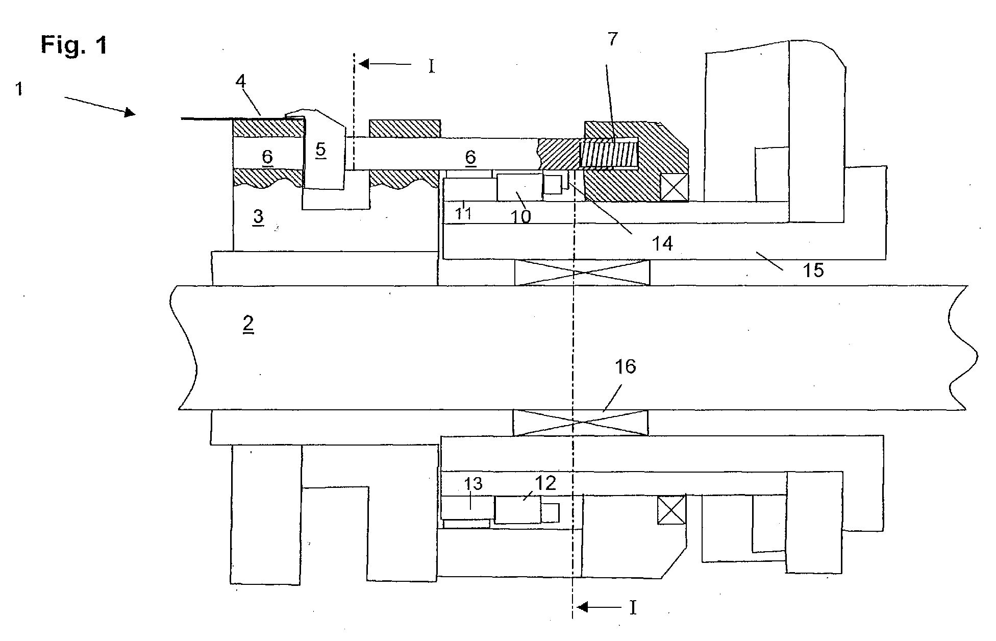
- FIG. 1 shows a view in the radial direction on a section of a Floor opening station according to the invention.
- This section shows the Bottom opening cylinder 1, which comprises a shaft 2.
- This wave 2 is in Not shown machine frame mounted and is driven.
- a support cylinder 3 is applied, on which the hose piece. 4 guided and held by the gripper fingers 5.
- the gripper finger 5 is with connected to a plunger 6.
- This plunger 6 is in holes in the support cylinder 3 mounted so that it is rotatable and axially displaceable.
- the compression spring 7 acts on the plunger 6 so with a force that the gripper fingers 5 always in the axial direction against the tube piece 4 leading part of Support cylinder 3 presses. From Fig. 2 it can be seen that a tension spring.
- control cams are provided on the plunger. 6 or on the lever 9 in the manner described below act:
- One of the axial cams 10, 12 acts on the sliding piece 14 and thus gives the plunger 6 a force. This force is that of the compression spring. 7 directed opposite and larger than this, so that ultimately the gripper fingers. 5 is removed in the axial direction of the tube piece 4.
- one of the two radial cams 11, 13 acts on a non-visible Slip piece, which is attached to the lever 9.
- the through the radial Control cam 11 applied force acts on the tension spring 8 and causes an additional lifting of the gripper finger 5 in the radial direction.
- the Control cams 10, 11, 12, 13 are attached to a carrier unit 15, which in turn connected to the machine frame.
- a support bearing 16 is provided between these two elements.
- the cams 10, 11 At the time at which the gripper finger 5, the tube piece 4 after Successful bottom opening again releases the desired size of the soil to be able to adjust, the cams 10, 11 in the direction of Double arrow B movable.
- the cams 10, 11 in a manner not shown connected to the carrier unit 15 quickly releasably.
- This bottom opening station 1 comprises a gripper finger 1.
- This gripper finger 1 is mounted on a plunger 6, which in turn is acted upon by compression spring 7 from the part of the support cylinder 3 leading the hose piece 4 with such a force, the gripper finger 5 is in a position away from the hose piece 4.
- the fixing of the hose piece 4 takes place with the aid of the axial control cam 10 and the radial control cam 11.
- the control cam 11 To lock the hose piece 4, first the control cam 11 imparts a force in the radial direction, so that the plunger 6 is rotated and the gripper finger 5 is lifted thereby.
- control cam 10 gives the gripper finger 5 a force, so that it against the force of the compression spring 7 in the direction of the hose piece 4 leading part of the support cylinder 3. This force must be maintained as long as the hose piece 4 is to be locked. This duration and thus the section length of the control cam 10 and 11 is dependent on the intended floor size of the hose piece 4. When changing the floor size, the section length of the control cam 10 and 11 must be adjusted. This is done in a known floor opening station by replacing the control cam 10 and moving cam 11.
Landscapes
- Supplying Of Containers To The Packaging Station (AREA)
- Control And Other Processes For Unpacking Of Materials (AREA)
Abstract
Die Erfindung betrifft eine Bodenöffnungsstation (1) einer Papierbeutelmaschine, welche einen Bodenöffnungszylinder (2) umfasst, welcher (2) zumindest einen Greiferfinger (3) aufweist, welcher (3) einen Beutelabschnitt greift und arretiert und welcher (3) dabei dem Beutelabschnitt eine Kraft in Richtung auf die Drehachse des Bodenöffnungszylinders vermittelt.The invention relates to a bottom opening station (1) of a paper bag machine, which comprises a bottom opening cylinder (2), which (2) at least one Gripper finger (3), which (3) engages and locks a bag portion and which (3) gives the bag portion a force in the direction of the axis of rotation of the Floor opening cylinder mediates.
Neu und erfinderisch ist, dass die zur Arretierung jeweils eines Beutelabschnitts
notwendige Kraft in Richtung auf den Beutelabschnitt und in Richtung auf die
Drehachse des Bodenöffnungszylinders von einem ersten Kraftbereitstellungsmittel
aufgebracht wird, welches diese Kraft während der gesamten Umdrehung des
Bodenöffnungszylinders bereitstellt. Ein zweites Kraftbereitstellungsmittel ist
vorgesehen, welches dem Greifer eine Kraft vermittelt, welche der Kraft des ersten
Kraftbereitstellungsmittels entgegenwirkt und den Greifer öffnet.
Description
Die Erfindung betrifft eine Bodenöffnungsstation einer Papierbeutelmaschine
nach dem Oberbegriff des Anspruchs 1.
Papierbeutelmaschinen sind seit langem bekannt. Beispielsweise zeigt die DE
197 02 144 A1 Elemente solcher Vorrichtungen. Die Patentschrift DE 1 080 846
zeigt einen Bodenmacherzylinder einer solchen Papierbeutelmaschine. Auf
einem Bodenmacherzylinder werden die Einschläge eines zuvor aufgezogenen
Endes eines Papierschlauches eingeschlagen und miteinander verleimt, so
dass sie den Boden eines Papierbeutels bilden. Zum Zulegen des Bodens
dienen Greiferfinger, die sowohl in axialer als auch in tangentialer Richtung des
Bodenmacherzylinders relativ zu diesem bewegt werden. Um die Greiferfinger
in Bewegung zu versetzen, werden diese teilweise mit Kräften beaufschlagt, die
von Steuerkurven bereitgestellt werden.The invention relates to a bottom opening station of a paper bag machine according to the preamble of
Paper bag machines have long been known. For example, DE 197 02 144 A1 shows elements of such devices. The
Ein weiteres Element einer solchen Papierbeutelmaschine wird in der
Patentschrift DE 17 61 992 C3 gezeigt. Das dort vorgestellte so genannte
Henkelaggregat dient zum Anbringen von Traggriffen an einen bereits
fertiggestellten Papierbeutel. Dazu wird ein Papierstreifen von einem Greifer auf
einem Zylinder festgelegt, vorgebrochen, gefalzt, mit Leim versehen und
letztendlich auf den Beutel aufgeklebt. Auf den Greifer wirkt eine von einer
Feder bereitgestellte Kraft in der Art, dass der Papierstreifen ständig von dem
Greifer auf der Zylinderoberfläche gehalten wird. Nach dem Verkleben des
Traggriffes mit dem Papierbeutel wird der Greifer mittels einer Steuerkurve
angehoben und zwecks Ergreifens eines neuen Papierstreifens wieder
abgesenkt. Another element of such a paper bag machine is in the
Die Druckschrift DE 41 15 161 A1 zeigt einen Ausschnitt eines Bodenmacherzylinders einer solchen Maschine. Dieser Bodenmacherzylinder ist das zentrale Bauteil einer jeden Beutelmaschine. In der Regel wird auf diesem Zylinder die Bodenbildung durchgeführt. Zur Öffnung dieses Bodens ist es jedoch zunächst notwendig, dass die Schlauchstücke, welche zuvor vereinzelt worden sind, zunächst an die Bodenöffnungsstation beziehungsweise den Bodenöffnungszylinder übergeben werden. Dort werden sie durch verschiedene Maßnahmen arretiert. Zu diesen Maßnahmen gehört oft die Beaufschlagung der Schlauchstücke mit Vakuum auf diesen Zylinder. In der Regel spielen jedoch Greifer eine Rolle. Die Schlauchstücke werden in diesen Beutelmaschinen bekanntlich in der Richtung der Schlauchsymmetrieachse gefördert. An den Seiten dieser Schlauchstücke oder in den Seitenfalten derselben werden neben den vorgenannten Vakuumbefestigungsmitteln daher auch Greifer zum Einsatz kommen. Naturgemäß werden in der Regel zwei Greifer eingesetzt, wobei auch die Verwendung eines oder gar mehrerer Greifer möglich erscheint. Beide Greifmechanismen, Vakuum und Greifer, werden oft zueinander ergänzend eingesetzt. Der Greifer wird hierbei mit einer Kraft beaufschlagt, welche ihn zum Zugreifen bringt, das heißt, dass der Greifer während der ganzen Zeit des Zugreifens aktiv mit einer Kraft beaufschlagt werden muss. Diese Kraft wird in der Regel von einem Kurvenpaket bereit gestellt. Die Zeit, während der der Beutel beziehungsweise das Schlauchstück, aus dem der Beutel gebildet werden wird, von dem Greifer oder den beiden Greifern gehalten werden muss, ist von der gewünschten Größe des zu bildenden Bodens abhängig. Daher werden bei der Änderung des Schlauchformates beziehungsweise der gewünschten Sacklänge Einstellungen zur formatgerechten Steuerung des Greifers notwendig. Die Kraft, die auf den Greifer ausgeübt wird, kommt in der Regel dadurch zustande, dass ein Stößel bei der Umdrehung des Bodenöffnungszylinders an einem Kurvenpaket entlang fährt, welches den Stößel so lange mit einer Kraft beaufschlagt, wie die Sackbestandteile beziehungsweise das Schlauchstück gehalten werden muss. Wird die gewünschte Bodengröße verändert, muss dieses Kurvenpaket daher völlig ausgetauscht werden. Diese Austauscharbeiten und die Bevorratung zahlreicher geeigneter Kurvenpakete für verschiedene Bodengrößen sind aufwändig. The document DE 41 15 161 A1 shows a section of a Bodenmacherzylinders such a machine. This floor maker cylinder is the central component of every bag machine. In general, it will open This bottoming out of this cylinder was done. To open this floor is However, it first necessary that the pieces of tubing, which previously have been isolated, first to the bottom opening station, respectively be handed over the bottom opening cylinder. There they are going through various measures arrested. These measures often include the Apply vacuum to this tube with vacuum. In the However, grippers usually play a role. The pieces of hose are in this Bag machines are known in the direction of the tube axis of symmetry promoted. On the sides of these pieces of tubing or in the gussets the same, therefore, in addition to the aforementioned vacuum fastening means also grippers are used. Naturally, usually two The use of grippers, including the use of one or more grippers possible appears. Both gripping mechanisms, vacuum and gripper, are often used in addition to each other. The gripper is doing this with a force applied, which brings him to access, that is, the gripper during the entire time of the access actively charged with a force must become. This force is usually prepared by a curve package posed. The time during which the bag or piece of tubing, from which the bag will be formed, from the gripper or the two Grippers must be kept to the desired size depending on the soil. Therefore, when changing the Tube formats or the desired bag length settings necessary for format-appropriate control of the gripper. The power on the Gripper is exercised, usually by the fact that a pestle during the rotation of the bottom opening cylinder along a curve package moves, which acts on the plunger as long as a force, as the Bag components or the hose piece must be kept. If the desired floor size is changed, this curve package must therefore be completely exchanged. These replacement works and the stocking numerous suitable cam packages for different floor sizes consuming.
Die Aufgabe der vorliegenden Erfindung ist es daher, eine Bodenöffnungsstation für Beutelmaschinen zu schaffen, welche bei einer Änderung der gewünschten Beutellänge ohne langwierige Einstellarbeiten und ohne die Bevorratung von Kurvenpaketen auskommt.The object of the present invention is therefore to provide a Bottom opening station for bag machines to create, which at a Change the desired bag length without tedious adjustments and without the provision of curve packages.
Diese Aufgabe wird durch die kennzeichnenden Merkmale des Anspruchs 1
gelöst. Zum Verständnis des Anspruchs 1 ist es wichtig zu verstehen, dass
nach dem Stand der Technik die zur Arretierung eines Beutelabschnitts
notwendige Kraft vor allem in Richtung auf die Drehachse des
Bodenöffnungszylinders wirkt. Der Beutelabschnitt wird also gegen den Zylinder
gedrückt. Die Länge dieser Kraftbereitstellung ist bei dem Stand der Technik,
wie erwähnt, von der Länge des Kurvenpaketes abhängig. Ist das Kurvenpaket
passiert, verebbt die arretierende Kraft und der Greifer öffnet sich.This object is achieved by the characterizing features of
Bei der vorliegenden Erfindung wird der Greifer während seiner ganzen Umdrehung zunächst von einer in Richtung auf die Achse des Greiferzylinders wirkenden Kraft beeinflusst. Lediglich wenn der Greifer geöffnet wird, wirkt dieser ersten Kraft eine zweite Kraft entgegen, die den Greifer öffnet. Vorteilhafterweise wird die erste Kraft von einem Federelement, einer magnetischen Kraft oder einer anderen Kraft aufbringenden Vorrichtung bereit gestellt. In the present invention, the gripper is during its whole Rotation first from one in the direction of the axis of the gripper cylinder affects acting force. Only when the gripper is opened, acts counteracting this first force with a second force which opens the gripper. Advantageously, the first force of a spring element, a magnetic force or other force applying device ready posed.
Die zweite Kraft wird in der Regel von zwei Kurvenpaketen bereitgestellt werden, wobei die Lage dieser beiden Kurvenpakete in Umfangsrichtung veränderlich ist. Durch diese Veränderbarkeit der Relativposition der beiden Kurvenpakete kann vorteilhafterweise eine Anpassung der Öffnungszeitpunkte des Greifers an die gewünschte Beutellänge vorgenommen werden.The second force is usually provided by two cam packages be, with the location of these two sets of curves in the circumferential direction is changeable. Due to this variability of the relative position of the two Curve packages can advantageously be an adaptation of the opening times of the gripper to the desired bag length.
Weitere Einzelheiten und Details der vorliegenden Erfindung sowie weitere Ausführungsbeispiele gehen aus den weiteren Ansprüchen, der Zeichnung und der gegenständlichen Beschreibung hervor. Die einzelnen Figuren zeigen:
- Fig. 1:
- Ansicht einer erfindungsgemäßen Bodenöffnungsstation
- Fig. 2:
- Ansicht gemäß I-I in Fig.1
- Fig. 3:
- Ansicht einer Bodenöffnungsstation nach dem Stand der Technik
- Fig. 1:
- View of a floor opening station according to the invention
- Fig. 2:
- View according to II in Fig.1
- 3:
- View of a floor opening station according to the prior art
Die Figur 1 zeigt eine Ansicht in radialer Richtung auf einen Ausschnitt einer
erfindungsgemäßen Bodenöffnungsstation. Dieser Ausschnitt zeigt den
Bodenöffnungszylinder 1, welcher eine Welle 2 umfasst. Diese Welle 2 ist im
nicht dargestellten Maschinengestell gelagert und ist antreibbar. Auf diese
Welle 2 ist ein Auflagezylinder 3 aufgebracht, auf welchem das Schlauchstück 4
geführt und durch den Greiferfinger 5 gehalten wird. Der Greiferfinger 5 ist mit
einem Stößel 6 verbunden. Dieser Stößel 6 ist in Bohrungen im Auflagezylinder
3 derart gelagert, dass er drehbar und axial verschiebbar ist. Die Druckfeder 7
beaufschlagt den Stößel 6 derart mit einer Kraft, dass der Greiferfinger 5 immer
in axialer Richtung gegen den das Schlauchstück 4 führenden Teil des
Auflagezylinders 3 drückt. Aus der Fig. 2 ist zu erkennen, dass eine Zugfeder 8
auf den Hebel 9 in Richtung auf die Welle 2 eine im wesentlichen radial
wirkende Kraft ausübt. Der Greiferfinger 5, der an dem Hebel 9 befestigt ist,
drückt somit das Schlauchstück 4 in radialer Richtung auf den das
Schlauchstück 4 führenden Teil des Auflagezylinders 3. Während des Betriebes
der Bodenöffnungsstation rotiert der Bodenöffnungszylinder 1 in Richtung des
Pfeiles A. FIG. 1 shows a view in the radial direction on a section of a
Floor opening station according to the invention. This section shows the
Zum Erfassen und zum Freigeben des zu formenden Bodens eines
Schlauchstücks 4 muss der Greiferfinger 5 zwei Mal von dem das
Schlauchstück 4 führende Teil des Auflagezylinders 3 entfernt werden. Zu
diesem Zweck sind Steuerkurven vorgesehen, die auf den Stößel 6
beziehungsweise auf den Hebel 9 in der im Folgenden beschriebenen Weise
wirken: Eine der axialen Steuerkurven 10, 12 wirkt auf das Schleifstück 14 und
vermittelt so dem Stößel 6 ein Kraft. Diese Kraft ist derjenigen der Druckfeder 7
entgegen gerichtet und größer als diese, so dass letztendlich der Greiferfinger 5
in axialer Richtung von dem Schlauchstück 4 entfernt wird. In etwa gleichzeitig
wirkt einer der beiden radiale Steuerkurven 11, 13 auf ein nicht sichtbares
Schleifstück, welches an dem Hebel 9 angebracht ist. Die durch die radiale
Steuerkurve 11 aufgebrachte Kraft wirkt der Zugfeder 8 entgegen und bewirkt
ein zusätzliches Anheben des Greiferfingers 5 in radialer Richtung. Der
Greiferfinger 5 befindet sich nun in einer so genannten geöffneten Position. Die
Steuerkurven 10, 11, 12, 13 sind an einer Trägereinheit 15 befestigt, welcher
wiederum mit dem Maschinengestell verbunden ist. Um einen konstanten
Abstand zwischen der Trägereinheit 15 und der Welle 2 zu gewährleisten, ist
zwischen diesen beiden Elementen ein Stützlager 16 vorgesehen.For detecting and releasing the soil to be formed
Die eigentliche Bodenöffnung erfolgt nun dadurch, dass der Greiferfinger 5 das
erste Kurvenpaket, bestehend aus den Steuerkurven 12 und 13, erreicht. In
diesem Moment wird das vorrauslaufende Ende des Schlauchstückes 4 mit
Hilfe eines nicht dargestellten Vakuumsaugers angehoben. Während dieser
Anhebebewegung laufen die Schleifstücke auf die Steuerkurven 12, 13, so dass
der Greiferfinger 5 geöffnet wird. Nach dem Passieren dieser Steuerkurven
schließt sich der Greiferfinger 5 wieder, wodurch das Schlauchstück 4 mit
seiner oberen Seite auf dem Auflagezylinder 3 arretiert wird. Durch die
Rotationsbewegung des Bodenöffnungszylinders 1 wird das Schlauchstück 4
aufgezogen. Erreicht der Greiferfinger 5 die Steuerkurven 10, 11, wird der
Greiferfinger 5 wieder geöffnet, so dass das Schlauchstück 4 mit dem nun
geöffneten Boden aus der Bodenöffnungsstation entfernt und einer weiteren
Verarbeitungsstation der Papierbeutelmaschine zugeführt werden kann. The actual bottom opening now takes place in that the
Um den Zeitpunkt, zu dem der Greiferfinger 5 das Schlauchstück 4 nach
erfolgter Bodenöffnung wieder frei gibt, der gewünschten Größe des Bodens
anpassen zu können, sind die Steuerkurven 10, 11 in Richtung des
Doppelpfeiles B verschiebbar. Zu diesem Zweck sind die Steuerkurven 10, 11
auf nicht gezeigte Weise schnell lösbar mit der Trägereinheit 15 verbunden.At the time at which the
Die Fig. 3 zeigt eine bereits bekannte Bodenöffnungsstation 1. Diese
Bodenöffnungsstation 1 umfasst einen Greiferfinger 1. Dieser Greiferfinger 1 ist
an einem Stößel 6 montiert, welcher wiederum über Druckfeder 7 von dem das
Schlauchstück 4 führende Teil des Auflagezylinders 3 mit einer solchen Kraft
beaufschlagt, dass der Greiferfinger 5 sich in einer vom Schlauchstück 4
entfernten Position befindet. Die Festlegung des Schlauchstückes 4 erfolgt
mithilfe der axialen Steuerkurve 10 und der radialen Steuerkurve 11. Zur
Arretierung des Schlauchstücks 4 vermittelt zunächst die Steuerkurve 11 eine
Kraft in radialer Richtung, so dass der Stößel 6 verdreht und der Greiferfinger 5
dadurch angehoben wird. Anschließend vermittelt die Steuerkurve 10 dem
Greiferfinger 5 eine Kraft, so dass dieser gegen die Kraft der Druckfeder 7 in
Richtung auf den das Schlauchstück 4 führende Teil des Auflagezylinders 3.
Diese Kraft muss so lange aufrecht erhalten werden, wie das Schlauchstück 4
arretiert werden soll. Diese Dauer und damit die Abschnittslänge der
Steuerkurve 10 und 11 ist abhängig von der vorgesehenen Bodengröße des
Schlauchstückes 4. Bei Veränderung der Bodengröße ist die Abschnittslänge
der Steuerkurve 10 und 11 anzupassen. Dies geschieht bei der einen
bekannten Bodenöffnungsstation durch Auswechseln der Steuerkurve 10 und
Verschieben von Steuerkurve 11.
Claims (6)
die zweiten Kraftbereitstellungsmittel zumindest zwei Kurvenpakete (10-13) umfassen, wobei die Relativposition dieser beiden Kurvenpakete (10-13) in der Umfangsrichtung (ϕ) des Bodenöffnungszylinders (1) veränderbar ist. Floor opening station (1) of a paper bag machine,
the second power supply means comprise at least two cam sets (10-13), wherein the relative position of these two cam packages (10-13) in the circumferential direction (φ) of the bottom opening cylinder (1) is variable.
dadurch gekennzeichnet, dass
die ersten Kraftbereitstellungsmittel (10 - 13) zumindest ein Federelement (7, 8) umfassen.Floor opening station (1) according to claim 1
characterized in that
the first power supply means (10 - 13) comprise at least one spring element (7, 8).
dadurch gekennzeichnet, dass
jedes Kurvenpaket (10 - 13) zumindest zwei Steuerkurven (10 -13) umfasst.Floor opening station (1) according to one of the preceding claims
characterized in that
each curve packet (10-13) comprises at least two control cams (10-13).
dadurch gekennzeichnet, dass
dem zumindest einen Greifer (5) durch die erste Steuerkurve (10, 12) eines jeden Kurvenpakets eine Kraft vermittelbar ist, welche in axialer Richtung des Bodenöffnungszylinders (1) von dem Beutelabschnitt (4) weg gerichtet ist.Floor opening station (1) according to the preceding claim
characterized in that
the at least one gripper (5) by the first control cam (10, 12) of each set of curves, a force is mediated, which in the axial direction of the bottom opening cylinder (1) of the bag portion (4) is directed away.
dadurch gekennzeichnet, dass
dem zumindest einen Greifer (5) durch die zweite Steuerkurve (11, 13) eines jeden Kurvenpakets eine Kraft vermittelbar ist, welche in radialer Richtung von der Drehachse des Bodenöffnungszylinders (1) weg gerichtet ist.Floor opening station (1) according to one of the two preceding claims
characterized in that
the at least one gripper (5) by the second control cam (11, 13) of each set of curves, a force is mediated, which is directed in the radial direction of the axis of rotation of the bottom opening cylinder (1) away.
die zweiten Kraftbereitstellungsmittel (10 - 13) die zweite Kraft zwei mal bei einer Umdrehung des Bodenöffnungszylinders (1) bereitstellen.Method for opening the gripper (5) of a floor opening station (1),
the second power supply means (10-13) provide the second power twice in one revolution of the bottom opening cylinder (1).
Applications Claiming Priority (2)
| Application Number | Priority Date | Filing Date | Title |
|---|---|---|---|
| DE10344156A DE10344156B4 (en) | 2003-09-22 | 2003-09-22 | Floor opening station of a paper bag machine |
| DE10344156 | 2003-09-22 |
Publications (3)
| Publication Number | Publication Date |
|---|---|
| EP1516718A2 true EP1516718A2 (en) | 2005-03-23 |
| EP1516718A3 EP1516718A3 (en) | 2006-09-13 |
| EP1516718B1 EP1516718B1 (en) | 2008-02-27 |
Family
ID=34177913
Family Applications (1)
| Application Number | Title | Priority Date | Filing Date |
|---|---|---|---|
| EP04021274A Expired - Lifetime EP1516718B1 (en) | 2003-09-22 | 2004-09-08 | Bottom opening station in a paper bag apparatus |
Country Status (3)
| Country | Link |
|---|---|
| EP (1) | EP1516718B1 (en) |
| AT (1) | ATE387307T1 (en) |
| DE (2) | DE10344156B4 (en) |
Cited By (2)
| Publication number | Priority date | Publication date | Assignee | Title |
|---|---|---|---|---|
| CN106881908A (en) * | 2017-03-22 | 2017-06-23 | 温州正博印刷机械有限公司 | A kind of moving corner device of paper |
| CN107225801A (en) * | 2017-08-02 | 2017-10-03 | 江苏方邦机械有限公司 | A kind of paper bag machine closes bottom device and paper bag machine |
Families Citing this family (2)
| Publication number | Priority date | Publication date | Assignee | Title |
|---|---|---|---|---|
| US8764618B2 (en) * | 2011-01-27 | 2014-07-01 | Duro Bag Manufacturing Company | Clampless bar mechanism for a paper bag bottoming mechanism |
| CN109397745A (en) * | 2018-12-11 | 2019-03-01 | 天津市津东华明纸箱厂 | A kind of carton bending forming mechanism |
Family Cites Families (6)
| Publication number | Priority date | Publication date | Assignee | Title |
|---|---|---|---|---|
| GB327643A (en) * | 1929-06-24 | 1930-04-10 | Alfred Clement Coty | Improvements in and relating to paper bag bottomers |
| US2044476A (en) * | 1934-04-27 | 1936-06-16 | Benjamin C Betner Company | Apparatus for making bags |
| US2123508A (en) * | 1937-03-15 | 1938-07-12 | Benjamin C Betner Company | Bag machine |
| DE1611699C2 (en) * | 1967-08-25 | 1975-11-20 | Windmoeller & Hoelscher, 4540 Lengerich | Device for producing the bottoms in a block bottom bag machine |
| DE4115161A1 (en) * | 1991-05-08 | 1992-11-12 | Windmoeller & Hoelscher | METHOD AND DEVICE FOR PRODUCING PAPER CARRYING BAGS |
| DE19702144C2 (en) * | 1997-01-22 | 2003-03-13 | Windmoeller & Hoelscher | Method and device for producing bags with handles |
-
2003
- 2003-09-22 DE DE10344156A patent/DE10344156B4/en not_active Expired - Fee Related
-
2004
- 2004-09-08 AT AT04021274T patent/ATE387307T1/en active
- 2004-09-08 EP EP04021274A patent/EP1516718B1/en not_active Expired - Lifetime
- 2004-09-08 DE DE502004006303T patent/DE502004006303D1/en not_active Expired - Lifetime
Cited By (3)
| Publication number | Priority date | Publication date | Assignee | Title |
|---|---|---|---|---|
| CN106881908A (en) * | 2017-03-22 | 2017-06-23 | 温州正博印刷机械有限公司 | A kind of moving corner device of paper |
| CN107225801A (en) * | 2017-08-02 | 2017-10-03 | 江苏方邦机械有限公司 | A kind of paper bag machine closes bottom device and paper bag machine |
| CN107225801B (en) * | 2017-08-02 | 2023-06-02 | 江苏方邦机械有限公司 | Paper bag machine closes end device and paper bag machine |
Also Published As
| Publication number | Publication date |
|---|---|
| DE10344156B4 (en) | 2008-02-07 |
| DE10344156A1 (en) | 2005-04-28 |
| ATE387307T1 (en) | 2008-03-15 |
| DE502004006303D1 (en) | 2008-04-10 |
| EP1516718A3 (en) | 2006-09-13 |
| EP1516718B1 (en) | 2008-02-27 |
Similar Documents
| Publication | Publication Date | Title |
|---|---|---|
| DE3742404C2 (en) | Method and device for transferring products | |
| DE2604101C2 (en) | Device for processing printed products | |
| DE2729605C2 (en) | Device for separating workpieces from a stack | |
| DE68901660T2 (en) | METHOD AND DEVICE FOR POSITIONING ELECTRICAL COMPONENTS. | |
| DE69405667T2 (en) | Device with a packaging wheel for feeding casings, especially in cigarette packaging machines | |
| DE4340858C2 (en) | cylinder | |
| DE102015112329A1 (en) | Taftmaschine | |
| DE2058606A1 (en) | Method and device for the lateral alignment of sheets, in particular in a printing press | |
| DE1602607A1 (en) | Conveyor device | |
| EP0574745B1 (en) | Device for separating piled sheets from synthetic material, paperbound or the like | |
| EP1516718B1 (en) | Bottom opening station in a paper bag apparatus | |
| DE2408066A1 (en) | BOW CONVEYOR | |
| DE10026731C2 (en) | Rotary tablet press for the production of multilayer tablets | |
| DE10138943A1 (en) | Food products transporting apparatus sweets including candies in wrapping machine has clamp jaw with setting screw to define gripping position | |
| EP1657008A1 (en) | Device for feeding strip material to a press | |
| EP3814257A1 (en) | Bottom-forming device and method for producing pieces of tubing provided with at least one bottom | |
| DE2117311C3 (en) | Device for pulling sheets of paper from a stack | |
| EP1378473B1 (en) | Sheet transport device with adjustable upper grippers for pockets | |
| EP1264692B1 (en) | Cleaning device for a cylinder of a printing machine | |
| CH629723A5 (en) | Sheet feeding device on a sheet-processing machine in which the drive of the conveying table takes place via a gearing with variable transmission ratio | |
| DE3143011A1 (en) | STEERING CONTROL GRIP DEVICE FOR PRINTED PAPER SHEETS | |
| DE69702108T2 (en) | Method and apparatus for the contactless delay of flat products | |
| DE2131004C3 (en) | Rotary printing press | |
| DE10139240B4 (en) | folding cylinder | |
| DE2308181C3 (en) | Machine for making boxes |
Legal Events
| Date | Code | Title | Description |
|---|---|---|---|
| PUAI | Public reference made under article 153(3) epc to a published international application that has entered the european phase |
Free format text: ORIGINAL CODE: 0009012 |
|
| AK | Designated contracting states |
Kind code of ref document: A2 Designated state(s): AT BE BG CH CY CZ DE DK EE ES FI FR GB GR HU IE IT LI LU MC NL PL PT RO SE SI SK TR |
|
| AX | Request for extension of the european patent |
Extension state: AL HR LT LV MK |
|
| PUAL | Search report despatched |
Free format text: ORIGINAL CODE: 0009013 |
|
| AK | Designated contracting states |
Kind code of ref document: A3 Designated state(s): AT BE BG CH CY CZ DE DK EE ES FI FR GB GR HU IE IT LI LU MC NL PL PT RO SE SI SK TR |
|
| AX | Request for extension of the european patent |
Extension state: AL HR LT LV MK |
|
| 17P | Request for examination filed |
Effective date: 20070313 |
|
| AKX | Designation fees paid |
Designated state(s): AT BE BG CH CY CZ DE DK EE ES FI FR GB GR HU IE IT LI LU MC NL PL PT RO SE SI SK TR |
|
| GRAP | Despatch of communication of intention to grant a patent |
Free format text: ORIGINAL CODE: EPIDOSNIGR1 |
|
| GRAS | Grant fee paid |
Free format text: ORIGINAL CODE: EPIDOSNIGR3 |
|
| GRAA | (expected) grant |
Free format text: ORIGINAL CODE: 0009210 |
|
| AK | Designated contracting states |
Kind code of ref document: B1 Designated state(s): AT BE BG CH CY CZ DE DK EE ES FI FR GB GR HU IE IT LI LU MC NL PL PT RO SE SI SK TR |
|
| REG | Reference to a national code |
Ref country code: GB Ref legal event code: FG4D Free format text: NOT ENGLISH |
|
| REG | Reference to a national code |
Ref country code: CH Ref legal event code: EP |
|
| REG | Reference to a national code |
Ref country code: IE Ref legal event code: FG4D Free format text: LANGUAGE OF EP DOCUMENT: GERMAN |
|
| REF | Corresponds to: |
Ref document number: 502004006303 Country of ref document: DE Date of ref document: 20080410 Kind code of ref document: P |
|
| PG25 | Lapsed in a contracting state [announced via postgrant information from national office to epo] |
Ref country code: FI Free format text: LAPSE BECAUSE OF FAILURE TO SUBMIT A TRANSLATION OF THE DESCRIPTION OR TO PAY THE FEE WITHIN THE PRESCRIBED TIME-LIMIT Effective date: 20080227 Ref country code: ES Free format text: LAPSE BECAUSE OF FAILURE TO SUBMIT A TRANSLATION OF THE DESCRIPTION OR TO PAY THE FEE WITHIN THE PRESCRIBED TIME-LIMIT Effective date: 20080607 |
|
| NLV1 | Nl: lapsed or annulled due to failure to fulfill the requirements of art. 29p and 29m of the patents act | ||
| PG25 | Lapsed in a contracting state [announced via postgrant information from national office to epo] |
Ref country code: PL Free format text: LAPSE BECAUSE OF FAILURE TO SUBMIT A TRANSLATION OF THE DESCRIPTION OR TO PAY THE FEE WITHIN THE PRESCRIBED TIME-LIMIT Effective date: 20080227 Ref country code: SI Free format text: LAPSE BECAUSE OF FAILURE TO SUBMIT A TRANSLATION OF THE DESCRIPTION OR TO PAY THE FEE WITHIN THE PRESCRIBED TIME-LIMIT Effective date: 20080227 |
|
| PG25 | Lapsed in a contracting state [announced via postgrant information from national office to epo] |
Ref country code: PT Free format text: LAPSE BECAUSE OF FAILURE TO SUBMIT A TRANSLATION OF THE DESCRIPTION OR TO PAY THE FEE WITHIN THE PRESCRIBED TIME-LIMIT Effective date: 20080721 Ref country code: SE Free format text: LAPSE BECAUSE OF FAILURE TO SUBMIT A TRANSLATION OF THE DESCRIPTION OR TO PAY THE FEE WITHIN THE PRESCRIBED TIME-LIMIT Effective date: 20080527 Ref country code: SK Free format text: LAPSE BECAUSE OF FAILURE TO SUBMIT A TRANSLATION OF THE DESCRIPTION OR TO PAY THE FEE WITHIN THE PRESCRIBED TIME-LIMIT Effective date: 20080227 Ref country code: CZ Free format text: LAPSE BECAUSE OF FAILURE TO SUBMIT A TRANSLATION OF THE DESCRIPTION OR TO PAY THE FEE WITHIN THE PRESCRIBED TIME-LIMIT Effective date: 20080227 Ref country code: DK Free format text: LAPSE BECAUSE OF FAILURE TO SUBMIT A TRANSLATION OF THE DESCRIPTION OR TO PAY THE FEE WITHIN THE PRESCRIBED TIME-LIMIT Effective date: 20080227 Ref country code: NL Free format text: LAPSE BECAUSE OF FAILURE TO SUBMIT A TRANSLATION OF THE DESCRIPTION OR TO PAY THE FEE WITHIN THE PRESCRIBED TIME-LIMIT Effective date: 20080227 |
|
| PG25 | Lapsed in a contracting state [announced via postgrant information from national office to epo] |
Ref country code: RO Free format text: LAPSE BECAUSE OF FAILURE TO SUBMIT A TRANSLATION OF THE DESCRIPTION OR TO PAY THE FEE WITHIN THE PRESCRIBED TIME-LIMIT Effective date: 20080227 |
|
| EN | Fr: translation not filed | ||
| PLBE | No opposition filed within time limit |
Free format text: ORIGINAL CODE: 0009261 |
|
| STAA | Information on the status of an ep patent application or granted ep patent |
Free format text: STATUS: NO OPPOSITION FILED WITHIN TIME LIMIT |
|
| 26N | No opposition filed |
Effective date: 20081128 |
|
| BERE | Be: lapsed |
Owner name: WINDMOLLER & HOLSCHER K.G. Effective date: 20080930 |
|
| PG25 | Lapsed in a contracting state [announced via postgrant information from national office to epo] |
Ref country code: EE Free format text: LAPSE BECAUSE OF FAILURE TO SUBMIT A TRANSLATION OF THE DESCRIPTION OR TO PAY THE FEE WITHIN THE PRESCRIBED TIME-LIMIT Effective date: 20080227 Ref country code: BG Free format text: LAPSE BECAUSE OF FAILURE TO SUBMIT A TRANSLATION OF THE DESCRIPTION OR TO PAY THE FEE WITHIN THE PRESCRIBED TIME-LIMIT Effective date: 20080527 Ref country code: FR Free format text: LAPSE BECAUSE OF FAILURE TO SUBMIT A TRANSLATION OF THE DESCRIPTION OR TO PAY THE FEE WITHIN THE PRESCRIBED TIME-LIMIT Effective date: 20081219 Ref country code: MC Free format text: LAPSE BECAUSE OF NON-PAYMENT OF DUE FEES Effective date: 20080930 |
|
| REG | Reference to a national code |
Ref country code: CH Ref legal event code: PL |
|
| PG25 | Lapsed in a contracting state [announced via postgrant information from national office to epo] |
Ref country code: CY Free format text: LAPSE BECAUSE OF FAILURE TO SUBMIT A TRANSLATION OF THE DESCRIPTION OR TO PAY THE FEE WITHIN THE PRESCRIBED TIME-LIMIT Effective date: 20080227 Ref country code: BE Free format text: LAPSE BECAUSE OF NON-PAYMENT OF DUE FEES Effective date: 20080930 |
|
| PG25 | Lapsed in a contracting state [announced via postgrant information from national office to epo] |
Ref country code: CH Free format text: LAPSE BECAUSE OF NON-PAYMENT OF DUE FEES Effective date: 20080930 Ref country code: LI Free format text: LAPSE BECAUSE OF NON-PAYMENT OF DUE FEES Effective date: 20080930 |
|
| PG25 | Lapsed in a contracting state [announced via postgrant information from national office to epo] |
Ref country code: HU Free format text: LAPSE BECAUSE OF FAILURE TO SUBMIT A TRANSLATION OF THE DESCRIPTION OR TO PAY THE FEE WITHIN THE PRESCRIBED TIME-LIMIT Effective date: 20080828 Ref country code: LU Free format text: LAPSE BECAUSE OF NON-PAYMENT OF DUE FEES Effective date: 20080908 |
|
| PG25 | Lapsed in a contracting state [announced via postgrant information from national office to epo] |
Ref country code: TR Free format text: LAPSE BECAUSE OF FAILURE TO SUBMIT A TRANSLATION OF THE DESCRIPTION OR TO PAY THE FEE WITHIN THE PRESCRIBED TIME-LIMIT Effective date: 20080227 |
|
| PG25 | Lapsed in a contracting state [announced via postgrant information from national office to epo] |
Ref country code: GR Free format text: LAPSE BECAUSE OF FAILURE TO SUBMIT A TRANSLATION OF THE DESCRIPTION OR TO PAY THE FEE WITHIN THE PRESCRIBED TIME-LIMIT Effective date: 20080528 |
|
| PGFP | Annual fee paid to national office [announced via postgrant information from national office to epo] |
Ref country code: IE Payment date: 20110912 Year of fee payment: 8 |
|
| PGFP | Annual fee paid to national office [announced via postgrant information from national office to epo] |
Ref country code: AT Payment date: 20110826 Year of fee payment: 8 |
|
| REG | Reference to a national code |
Ref country code: AT Ref legal event code: MM01 Ref document number: 387307 Country of ref document: AT Kind code of ref document: T Effective date: 20120908 |
|
| REG | Reference to a national code |
Ref country code: IE Ref legal event code: MM4A |
|
| PG25 | Lapsed in a contracting state [announced via postgrant information from national office to epo] |
Ref country code: IE Free format text: LAPSE BECAUSE OF NON-PAYMENT OF DUE FEES Effective date: 20120908 Ref country code: AT Free format text: LAPSE BECAUSE OF NON-PAYMENT OF DUE FEES Effective date: 20120908 |
|
| REG | Reference to a national code |
Ref country code: DE Ref legal event code: R079 Ref document number: 502004006303 Country of ref document: DE Free format text: PREVIOUS MAIN CLASS: B31B0001780000 Ipc: B31B0050780000 |
|
| PGFP | Annual fee paid to national office [announced via postgrant information from national office to epo] |
Ref country code: GB Payment date: 20180928 Year of fee payment: 15 |
|
| PGFP | Annual fee paid to national office [announced via postgrant information from national office to epo] |
Ref country code: DE Payment date: 20180930 Year of fee payment: 15 |
|
| PGFP | Annual fee paid to national office [announced via postgrant information from national office to epo] |
Ref country code: IT Payment date: 20180927 Year of fee payment: 15 |
|
| REG | Reference to a national code |
Ref country code: DE Ref legal event code: R119 Ref document number: 502004006303 Country of ref document: DE |
|
| PG25 | Lapsed in a contracting state [announced via postgrant information from national office to epo] |
Ref country code: DE Free format text: LAPSE BECAUSE OF NON-PAYMENT OF DUE FEES Effective date: 20200401 |
|
| PG25 | Lapsed in a contracting state [announced via postgrant information from national office to epo] |
Ref country code: IT Free format text: LAPSE BECAUSE OF NON-PAYMENT OF DUE FEES Effective date: 20190908 |
|
| GBPC | Gb: european patent ceased through non-payment of renewal fee |
Effective date: 20190908 |
|
| PG25 | Lapsed in a contracting state [announced via postgrant information from national office to epo] |
Ref country code: GB Free format text: LAPSE BECAUSE OF NON-PAYMENT OF DUE FEES Effective date: 20190908 |