EP1516567A1 - Ausziehbares Plattformbett - Google Patents
Ausziehbares Plattformbett Download PDFInfo
- Publication number
- EP1516567A1 EP1516567A1 EP03021084A EP03021084A EP1516567A1 EP 1516567 A1 EP1516567 A1 EP 1516567A1 EP 03021084 A EP03021084 A EP 03021084A EP 03021084 A EP03021084 A EP 03021084A EP 1516567 A1 EP1516567 A1 EP 1516567A1
- Authority
- EP
- European Patent Office
- Prior art keywords
- frame
- axes
- movement
- sector
- retraction
- Prior art date
- Legal status (The legal status is an assumption and is not a legal conclusion. Google has not performed a legal analysis and makes no representation as to the accuracy of the status listed.)
- Granted
Links
- 230000007246 mechanism Effects 0.000 claims abstract description 57
- 230000001360 synchronised effect Effects 0.000 claims abstract description 12
- 238000013016 damping Methods 0.000 claims description 6
- 230000000694 effects Effects 0.000 description 2
- 238000004519 manufacturing process Methods 0.000 description 2
- 230000002411 adverse Effects 0.000 description 1
- 210000003423 ankle Anatomy 0.000 description 1
- 230000001419 dependent effect Effects 0.000 description 1
- 238000006073 displacement reaction Methods 0.000 description 1
- 238000009434 installation Methods 0.000 description 1
- 238000012423 maintenance Methods 0.000 description 1
- 238000004804 winding Methods 0.000 description 1
Images


Classifications
-
- A—HUMAN NECESSITIES
- A47—FURNITURE; DOMESTIC ARTICLES OR APPLIANCES; COFFEE MILLS; SPICE MILLS; SUCTION CLEANERS IN GENERAL
- A47C—CHAIRS; SOFAS; BEDS
- A47C19/00—Bedsteads
- A47C19/04—Extensible bedsteads, e.g. with adjustment of length, width, height
- A47C19/045—Extensible bedsteads, e.g. with adjustment of length, width, height with entire frame height or inclination adjustments
-
- A—HUMAN NECESSITIES
- A47—FURNITURE; DOMESTIC ARTICLES OR APPLIANCES; COFFEE MILLS; SPICE MILLS; SUCTION CLEANERS IN GENERAL
- A47C—CHAIRS; SOFAS; BEDS
- A47C17/00—Sofas; Couches; Beds
- A47C17/84—Suspended beds, e.g. suspended from ceiling
-
- A—HUMAN NECESSITIES
- A47—FURNITURE; DOMESTIC ARTICLES OR APPLIANCES; COFFEE MILLS; SPICE MILLS; SUCTION CLEANERS IN GENERAL
- A47C—CHAIRS; SOFAS; BEDS
- A47C19/00—Bedsteads
- A47C19/20—Multi-stage bedsteads; Bedsteads stackable to multi-stage bedsteads
- A47C19/207—Mezzanine beds
Definitions
- the subject of the present invention is a device serving as a retractable bed mezzanine comprising a frame equipped with a frame, a retraction mechanism retracting the bed frame from a first use position to a second storage position.
- the furniture can be used in a first position to then be transformed into his second position in order to free up space.
- the furniture can serve as bed during the night to be transformed during the day in order to have more space in the room.
- the document FR 2 729 062 describes in particular a retractable bed composed of a frame, a frame and a mechanism to position the frame horizontally at several positions in height, the bed can be used or stored.
- the retraction mechanism used in this case works by means of electric drives comprising in particular a motor.
- the object of the present invention is to provide a device tending to obviate the aforementioned drawbacks of current systems.
- the subject of the present invention is a device serving as a retractable bed a mezzanine comprising the features set forth in claim 1.
- the mechanism of retraction of the device comprises two axes positioned on a bed frame, each of these axes being connected by a connecting rod to a pivot on a frame, in order to connect the frame and the frame, and a mechanism of synchronization of the movement connecting these two axes and imposing a rotation synchronized of the two axes.
- the retraction mechanism comprises at least one minus one link on each axis, these links being articulated on arms to form a deformable parallelogram imposing a synchronized rotation both axes.
- the mechanism is arranged, in reducing the number of parts and optimizing their location, so efficient and simple to reduce production costs and maintenance. He can be easily installed inside a box integrated naturally in the frame supporting the bedspring of the bed in order to have a presentation aesthetically attractive furniture.
- the mechanism may include at least one sector and a lever or two sectors positioned on the axes, these being connected by one or more springs.
- the spring provides a force facilitating the displacement of a position of the frame to another.
- the transformable furniture according to the present invention can serve as a bed in its use position and makes it easy to clear space in its storage position, for example to use a desk, table or other things installed under the bed frame.
- the bed retractable according to the present invention is an independent assembly constituting a retractable mezzanine.
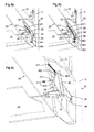
- This mezzanine consists of a frame 10 formed of four poles vertical 11 connected together by a rigid structure 12, 13, 14, for example triangulated, ensuring the stability and rigidity of the whole.
- This frame 10 serves to support a horizontal frame 20 formed normally of two longitudinal boxes 21 connected by two transverse boards 22, as indicated in FIG. 2 where the faces of the boxes 21 hiding in this view the retraction mechanism are not shown.
- Frame 20 could also be formed by two transverse boxes connected by two boards by changing the location of the retraction mechanisms in consequently, as will be apparent from the following explanations.
- the frame 20 could be formed by a box and a beam corresponding to the second box, these two pieces being of again connected by two boards.
- Each box 21 of the frame 20 contains a retraction mechanism 30 having two axes 31, as shown in Figure 3 where the outer face interior of the caissons is not shown to show the details of the mechanism 30.
- An axle 31 of a retraction mechanism 30 may physically crossing the entire frame 20 by connecting two mechanisms 30 in the boxes 21 located on each side of the frame 20 or can only have the length corresponding to the thickness of a box 21. From preferably, at least one of the two axes 31 of a retraction mechanism 30 crosses the frame 20, as shown in Figure 3.
- Each of these axes 31 is connected at its outer ends by a connecting rod 32 to a pivot 33 that includes each post 11 of the frame 10.
- the location of the pivot 33 in the posts 11 and the the length of the rods 32 are chosen so that, on the one hand, the position of storage of the frame 20 free space enough to use the place below this frame 20 and that, on the other hand, the position of use of the bed and in particular frame 20 is at a suitable height.
- the device can also be equipped with a ladder 23 allowing the user to climb into the bed without any effort, as shown in Figure 1b.
- Each axis 31 of the retraction mechanism 30 of each box 21 carries at least one rod 34, the ends of the two rods 34 of the two axes 31 being articulated on arms 35 to form a parallelogram deformable device imposing a synchronized rotation of the two axes 31.
- two opposite sides, longitudinal or transverse, of the frame 20 are equipped of a retraction mechanism 30, that is to say that arms 35 are thus in two boxes 21 located on two opposite sides of the frame 20.
- the second caisson can be replaced by a simple beam, as mentioned above, this beam not comprising that a pivot 33 connected by a connecting rod 32 to the axis 31 instead of a mechanism full retraction 30.
- the system retraction of a frame 20 has two retraction mechanisms 30 and is therefore symmetrical.
- the rods 34 are preferably mounted perpendicularly to the corresponding rod 32, as shown in Figure 3, and the arms 35 comprise, at each of their ends, an arcuate portion rounding the corners of the deformable parallelogram to allow the maximum bringing the arms 35 into the horizontal position of the rod 34, that is to say in the storage position 20a and use 20b of the frame 20, where the articulation links between the links 34 and the arms 35 must find the place between the two corresponding arms.
- This set of rods 34 and arm 35 forms a mechanism for synchronizing the movement of the axes 31.
- a variant among several others, not shown, to the solution previous to form such a motion synchronization mechanism has at least one pinion on each axis 31, these pinions being connected by a chain to form a kinematic connection imposing a rotation synchronized two axes 31. It is obvious that the pinion and chain assembly is equivalent to the mechanism using rods 34 and arms 35, and the remarks in the previous paragraph apply in a similar way to this solution.
- the motion synchronization mechanism that is positioned on the axes 31 and connects these two axes 31 by imposing a synchronized rotation of the two axes 31 is part of the retraction mechanism 30 and can be realized In a different way.
- Each axis 31 of the retraction mechanism 30 of each box 21 can still carry at least one sector 36, the two sectors 36 of a mechanism 30 being connected by one or more springs 37.
- the force of the springs 37 assists the up and down the downward movement of the frame 20.
- the force of the springs 37 can be adjusted through the aforementioned sectors 36 because the springs 37 or corresponding intermediate links, for example a wire 371 between a sector 36 and a spring 37, can be hooked to several places along the outer perimeter of each sector 36 thus putting the springs 37 under a more or less strong tension and simultaneously allowing change the angle of attack of a spring.
- One or even both sectors 36 can also be replaced by a simple lever by limiting or even removing the possibility of varying the torque exerted by the springs 37 on the sectors 36. set of sectors and springs thus plays the role of a training device for the retraction mechanism to facilitate the movement of the frame by the user. In order to cite an alternative solution, this provision could be replaced for example by spiral springs mounted individually on the axes 31.
- Figures 4a to 4c show in detail one of the embodiments possible of such a sector 36 on which is engaged a wire 371 connecting it to the spring corresponding 37.
- this sector 36 Along the outer periphery of this sector 36 are arranged several holes 361 for inserting a stop pin 362 on which the above-mentioned wire 371 is fixed, this being represented in FIG. 4a.
- the tension exerted on the spring 37 as well as its angle of attack with respect to the sector 36 can be set.
- orifices 211 are provided in the inner planks of the boxes 21 of a frame 20, for example in front of the holes 361 of the sector 36, the frame 20 being in the position of storage 20a. These orifices 211 and the pins 362 and 363 are illustrated in the FIG. 4c, the extension peg 363 being shown in its position cleared and in the engaged position.
- the connecting rods 32, the rods 34 and, where appropriate, the sectors 36 are fixed rigidly by in relation to others and preferably also to these axes. also be attached to the frame 31. in which the rods 32. the rods 34 and the where appropriate the sectors 36 are fixed rigidly relative to one another and the axes 31 rotated face on this set.
- pivots 33 which are pivotally mounted either in the rods 32 or in posts 11 (or both).
- the device may further comprise a locking device allowing to lock the frame 20 in at least one of its extreme positions.
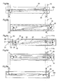
- This locking device can be integrated in the axes 31, as illustrated in FIGS. Figures 5a and 5b.
- an axis 31 of a retraction mechanism is this effect achieved by a tube of a length corresponding approximately to the thickness of a box 21 and pivotally mounted in the frame 20 forming a rigid assembly with the rod 32, the link 34 and, where appropriate, the sector 36.
- this axis 31 is housed a cylindrical body 311, a tube or a cylinder, a slightly longer length than the axis 31.
- the body 311 is cut into bevel at the outer end facing the post 11 of the frame 10 and comprises a pin 312 at the inner end.
- a guide 313 with grooves receiving the pin 312 of the body 311 is fixed to the frame 20 so as to constrain the movement of the body 311 in the axis 31 forward and backward by preventing simultaneously its rotation.
- At least one spring 314 makes it possible to push the body 311 to the outside, the latter being able to retract inside the frame 20 when its outer end cut bevel touches the post 11.
- the latter is equipped with at least one stop, for example in the form of a striker 111 formed in the pole in front of the positions where the body 311 comes in the low position and / or high of the frame 20.
- the body 311 can snap into the striker 111 in the post, thereby locking the frame 20 in its storage position at the top or the use position at the bottom.
- the locking device can also placed elsewhere in the box 21, instead of being placed in the axis 31, while remaining able to cooperate with the frame 10.
- this locking device can be provided for example at the front part of the bed, preferably on each side, the front axle is therefore physically in two parts, while the rear axis of the bed can be in one piece to better synchronize frame movement physically connecting the two retraction mechanisms 30 housed in two boxes 21 on each side of the frame 20.
- a damping device 38 may be provided on the frame 20 or on the frame 10. As shown in FIG. 5a, this damping device 38 can be constituted by a hydraulic stop positioned inside a box 21 of so that it cooperates with the retraction mechanism 30, for example a sector 36, for damping the frame 20 driven in the upper position 20a by the springs 37. It could also be constituted by a spring, a rubber OR any other means capable of fulfilling this depreciation function, and the cooperation could be done with the rod 34, the connecting rod 32 or another piece of the mechanism of retraction 30.
- FIG. 6a shows the frame 20 in the high position, that is to say in the storage position 20a.
- the frame is locked again if equipped with the locking device described above. he It should be noted that during this movement the springs 37 are stretched compensating the weight of the frame 20 and allowing easy and smooth movement.
- the force exerted by the springs 37 increases from the position of storage 20a to become maximum in the intermediate position of the figure 6d and then decrease slightly to the position of use 20b. She can be adjusted using the aforementioned sectors 36 and pegs 362, 363, forming a mechanism for adjusting the force of the springs 37.
- the frame 20 can serve as a support for a bed base and a mattress for constitute a retractable mezzanine.
- the dimensions of frame 20 depend the size of the desired bed and can for example correspond to a single bed or a bed double.
- the length of the connecting rods 32 and the location of the pivots 33 of these two frames 20 are preferably selected in such a way that the storage positions 20a of the two frames 20 are relatively close to each other while the positions 20b are similar to the positions of the bunk bed bases normal.
- the movement plans of the rods 32 of the two frames 20 must be slightly offset to allow the connecting rod 32 of the frame can pass the pivot 33 of the high frame.
- the Murphy bed in mezzanine is characterized primarily by the characteristics following: It presents a frame, this frame being equipped with a frame. A mechanism allows to retract the frame from a first low position of use to a second high storage position.
- the mechanism positioned on the frame, comprises two axes, each of these axes being connected by a connecting rod to a pivot on the frame, in order to connect the frame and the frame. It still has a mechanism for synchronization of the movement connecting these two axes and imposing a rotation synchronized of the two axes.
- This mechanism of motion synchronization can be achieved by at least one rod on each axis, these rods being articulated on arms to form a deformable parallelogram imposing a synchronized rotation of the two axes.
- the retraction mechanism also includes, on these axes, at least one sector and a lever or two sectors, these being connected by one or more springs in order to have a drive device to provide a force facilitating the movement of a position to the other of the frame.
- the device according to the present invention thus makes available a piece of furniture transformable that can be used as bed at night in its position of use and occupying little space during the day in its storage position, this goal being completed in a simple, efficient and inexpensive way thanks to the characteristics above.
Landscapes
- Health & Medical Sciences (AREA)
- General Health & Medical Sciences (AREA)
- Nursing (AREA)
- Invalid Beds And Related Equipment (AREA)
- Accommodation For Nursing Or Treatment Tables (AREA)
- Orthopedics, Nursing, And Contraception (AREA)
Priority Applications (5)
| Application Number | Priority Date | Filing Date | Title |
|---|---|---|---|
| DE60323976T DE60323976D1 (de) | 2003-09-18 | 2003-09-18 | Ausziehbares Plattformbett |
| AT03021084T ATE410099T1 (de) | 2003-09-18 | 2003-09-18 | Ausziehbares plattformbett |
| EP03021084A EP1516567B1 (de) | 2003-09-18 | 2003-09-18 | Ausziehbares Plattformbett |
| US10/572,392 US7552486B2 (en) | 2003-09-18 | 2004-07-20 | Stowable mezzanine bed |
| PCT/IB2004/002459 WO2005025380A1 (fr) | 2003-09-18 | 2004-07-20 | Lit escamotable en mezzanine |
Applications Claiming Priority (1)
| Application Number | Priority Date | Filing Date | Title |
|---|---|---|---|
| EP03021084A EP1516567B1 (de) | 2003-09-18 | 2003-09-18 | Ausziehbares Plattformbett |
Publications (2)
| Publication Number | Publication Date |
|---|---|
| EP1516567A1 true EP1516567A1 (de) | 2005-03-23 |
| EP1516567B1 EP1516567B1 (de) | 2008-10-08 |
Family
ID=34178430
Family Applications (1)
| Application Number | Title | Priority Date | Filing Date |
|---|---|---|---|
| EP03021084A Expired - Lifetime EP1516567B1 (de) | 2003-09-18 | 2003-09-18 | Ausziehbares Plattformbett |
Country Status (5)
| Country | Link |
|---|---|
| US (1) | US7552486B2 (de) |
| EP (1) | EP1516567B1 (de) |
| AT (1) | ATE410099T1 (de) |
| DE (1) | DE60323976D1 (de) |
| WO (1) | WO2005025380A1 (de) |
Families Citing this family (9)
| Publication number | Priority date | Publication date | Assignee | Title |
|---|---|---|---|---|
| USD583586S1 (en) | 2007-05-08 | 2008-12-30 | Gudenkauf John G | Bed system |
| US7874026B2 (en) * | 2007-08-24 | 2011-01-25 | Double Space Bed Systems, Inc. | System and method for raising and lowering a bed |
| US8856982B1 (en) * | 2010-07-13 | 2014-10-14 | Christopher George Kalivas | Motion bed |
| US11134787B2 (en) | 2018-05-16 | 2021-10-05 | Bestar Inc. | Anti-shearing and anti-crushing device on a retractable bed |
| USD880174S1 (en) * | 2018-11-09 | 2020-04-07 | Ori Inc. | Furniture item |
| USD880185S1 (en) * | 2018-11-09 | 2020-04-07 | Ori Inc. | Furniture item |
| CA3120146A1 (en) * | 2020-05-15 | 2021-11-15 | Bestar Inc. | Automated safety locking device for wall beds |
| USD1015002S1 (en) * | 2021-06-28 | 2024-02-20 | Comptree, Inc. | Loft bed |
| CN114164980B (zh) * | 2021-12-16 | 2023-09-29 | 四川润邦建材有限公司 | 一种多功能可升降式吊顶 |
Citations (3)
| Publication number | Priority date | Publication date | Assignee | Title |
|---|---|---|---|---|
| US3745595A (en) * | 1972-08-29 | 1973-07-17 | Kwikee Enterprises Inc | Suspension means for bunk beds |
| US3829912A (en) * | 1971-09-01 | 1974-08-20 | Flexsteel Industries | Retractable bed assemblies |
| FR2591876A1 (fr) * | 1985-12-20 | 1987-06-26 | Avril Joel | Dispositif de lit escamotable place dans une surelevation repliable de vehicule ou dans un lieu d'habitation |
Family Cites Families (4)
| Publication number | Priority date | Publication date | Assignee | Title |
|---|---|---|---|---|
| IT1177944B (it) | 1984-07-31 | 1987-08-26 | Pietro Crocoli | Letto retrattile a scomparsa |
| ES293860Y (es) | 1986-04-28 | 1987-05-16 | Fernandez Romero Juan | Cama-litera abatible con dispositivo de seguridad |
| JPH07119Y2 (ja) | 1988-03-18 | 1995-01-11 | 三和シヤッター工業株式会社 | 電動式昇降ベッド |
| FR2729062A1 (fr) | 1995-01-11 | 1996-07-12 | Dievart Rene Charles | Equipement muni d'une partie mobile entre des positions haute et basse, et element de mobilier, notamment mezzanine elevatrice, ainsi agencee |
-
2003
- 2003-09-18 EP EP03021084A patent/EP1516567B1/de not_active Expired - Lifetime
- 2003-09-18 AT AT03021084T patent/ATE410099T1/de not_active IP Right Cessation
- 2003-09-18 DE DE60323976T patent/DE60323976D1/de not_active Expired - Lifetime
-
2004
- 2004-07-20 WO PCT/IB2004/002459 patent/WO2005025380A1/fr not_active Ceased
- 2004-07-20 US US10/572,392 patent/US7552486B2/en not_active Expired - Lifetime
Patent Citations (3)
| Publication number | Priority date | Publication date | Assignee | Title |
|---|---|---|---|---|
| US3829912A (en) * | 1971-09-01 | 1974-08-20 | Flexsteel Industries | Retractable bed assemblies |
| US3745595A (en) * | 1972-08-29 | 1973-07-17 | Kwikee Enterprises Inc | Suspension means for bunk beds |
| FR2591876A1 (fr) * | 1985-12-20 | 1987-06-26 | Avril Joel | Dispositif de lit escamotable place dans une surelevation repliable de vehicule ou dans un lieu d'habitation |
Also Published As
| Publication number | Publication date |
|---|---|
| DE60323976D1 (de) | 2008-11-20 |
| WO2005025380A1 (fr) | 2005-03-24 |
| EP1516567B1 (de) | 2008-10-08 |
| ATE410099T1 (de) | 2008-10-15 |
| US20070074342A1 (en) | 2007-04-05 |
| US7552486B2 (en) | 2009-06-30 |
Similar Documents
| Publication | Publication Date | Title |
|---|---|---|
| EP0194951B1 (de) | Winkelregulierungsvorrichtung für Rollvorhänge oder dergleichen | |
| EP1516567A1 (de) | Ausziehbares Plattformbett | |
| FR2786996A1 (fr) | Siege muni d'un dispositif d'aide pour se lever | |
| EP0575243A1 (de) | Fahrzeugsitz mit mehrfachen Einstellungen | |
| EP0231698B1 (de) | Umklappbare Fahrzeugsitze | |
| FR2474084A1 (fr) | Dispositif a store suspendu et enrouleur pour la realisation d'une marquise | |
| EP1769954A1 (de) | Sonnenblendenvorrichtung für eine Fahrzeugwindschutzscheibe, mit einem Rollo, und entsprechendes Fahrzeug | |
| EP1725138B1 (de) | Lagerungsvorrichtung | |
| FR2931397A1 (fr) | Store pour partie superieure de vitre de portiere de vehicule automobile, et portiere correspondante | |
| EP1336519B1 (de) | Fensterrolle für Kraftfahrzeug mit Zugstange mit mobiler Abdeckung | |
| EP2183444B1 (de) | Einzelkonsolenmarkise | |
| FR2927780A1 (fr) | Ombrelle coupe-vent pour meuble d'exterieur | |
| FR2918929A1 (fr) | Store d'occultation pour vehicule automobile, a barre de tirage basculante, et vehicule automobile correspondant | |
| EP3346072B1 (de) | Markisenstruktur | |
| EP0319443B1 (de) | Jalousie | |
| EP1530928A1 (de) | Zusammenklappbarer Stuhl mit einem niedrigen Profil in der zusammengeklappten Position | |
| EP0356295A1 (de) | Wohnwagen mit klappbaren, starren Wänden mit einem oder mehreren Anordnungsmöbeln im Dach | |
| WO2004023940A1 (fr) | Ensemble de lit(s) escamotable | |
| FR2891493A1 (fr) | Palettes pare-soleil pour pare-brise de vehicule automobile, a store a enrouleur, et vehicule automobile correspondant. | |
| FR2613917A1 (fr) | Armoire de toilette | |
| EP2955060A1 (de) | Versenkbarer einbauschrank über einer duschwanne, der in versenkter position freien zutritt zur duschwanne lässt | |
| BE903832R (fr) | Perfectionnements a une echelle repliable. | |
| FR2733274A1 (fr) | Store a enrouleur a biellettes dentees | |
| FR2748194A1 (fr) | Canape-lit transformable escamotable par relevage a la verticale | |
| BE521053A (de) |
Legal Events
| Date | Code | Title | Description |
|---|---|---|---|
| PUAI | Public reference made under article 153(3) epc to a published international application that has entered the european phase |
Free format text: ORIGINAL CODE: 0009012 |
|
| AK | Designated contracting states |
Kind code of ref document: A1 Designated state(s): AT BE BG CH CY CZ DE DK EE ES FI FR GB GR HU IE IT LI LU MC NL PT RO SE SI SK TR |
|
| AX | Request for extension of the european patent |
Extension state: AL LT LV MK |
|
| 17P | Request for examination filed |
Effective date: 20050906 |
|
| AKX | Designation fees paid |
Designated state(s): AT BE BG CH CY CZ DE DK EE ES FI FR GB GR HU IE IT LI LU MC NL PT RO SE SI SK TR |
|
| GRAP | Despatch of communication of intention to grant a patent |
Free format text: ORIGINAL CODE: EPIDOSNIGR1 |
|
| GRAS | Grant fee paid |
Free format text: ORIGINAL CODE: EPIDOSNIGR3 |
|
| GRAA | (expected) grant |
Free format text: ORIGINAL CODE: 0009210 |
|
| AK | Designated contracting states |
Kind code of ref document: B1 Designated state(s): AT BE BG CH CY CZ DE DK EE ES FI FR GB GR HU IE IT LI LU MC NL PT RO SE SI SK TR |
|
| REG | Reference to a national code |
Ref country code: GB Ref legal event code: FG4D Free format text: NOT ENGLISH |
|
| REG | Reference to a national code |
Ref country code: CH Ref legal event code: EP |
|
| REG | Reference to a national code |
Ref country code: IE Ref legal event code: FG4D Free format text: LANGUAGE OF EP DOCUMENT: FRENCH |
|
| REF | Corresponds to: |
Ref document number: 60323976 Country of ref document: DE Date of ref document: 20081120 Kind code of ref document: P |
|
| REG | Reference to a national code |
Ref country code: CH Ref legal event code: NV Representative=s name: MICHELI & CIE SA |
|
| PG25 | Lapsed in a contracting state [announced via postgrant information from national office to epo] |
Ref country code: SI Free format text: LAPSE BECAUSE OF FAILURE TO SUBMIT A TRANSLATION OF THE DESCRIPTION OR TO PAY THE FEE WITHIN THE PRESCRIBED TIME-LIMIT Effective date: 20081008 |
|
| NLV1 | Nl: lapsed or annulled due to failure to fulfill the requirements of art. 29p and 29m of the patents act | ||
| PG25 | Lapsed in a contracting state [announced via postgrant information from national office to epo] |
Ref country code: BG Free format text: LAPSE BECAUSE OF FAILURE TO SUBMIT A TRANSLATION OF THE DESCRIPTION OR TO PAY THE FEE WITHIN THE PRESCRIBED TIME-LIMIT Effective date: 20090108 Ref country code: AT Free format text: LAPSE BECAUSE OF FAILURE TO SUBMIT A TRANSLATION OF THE DESCRIPTION OR TO PAY THE FEE WITHIN THE PRESCRIBED TIME-LIMIT Effective date: 20081008 Ref country code: ES Free format text: LAPSE BECAUSE OF FAILURE TO SUBMIT A TRANSLATION OF THE DESCRIPTION OR TO PAY THE FEE WITHIN THE PRESCRIBED TIME-LIMIT Effective date: 20090119 |
|
| PG25 | Lapsed in a contracting state [announced via postgrant information from national office to epo] |
Ref country code: FI Free format text: LAPSE BECAUSE OF FAILURE TO SUBMIT A TRANSLATION OF THE DESCRIPTION OR TO PAY THE FEE WITHIN THE PRESCRIBED TIME-LIMIT Effective date: 20081008 Ref country code: PT Free format text: LAPSE BECAUSE OF FAILURE TO SUBMIT A TRANSLATION OF THE DESCRIPTION OR TO PAY THE FEE WITHIN THE PRESCRIBED TIME-LIMIT Effective date: 20090218 Ref country code: NL Free format text: LAPSE BECAUSE OF FAILURE TO SUBMIT A TRANSLATION OF THE DESCRIPTION OR TO PAY THE FEE WITHIN THE PRESCRIBED TIME-LIMIT Effective date: 20081008 |
|
| REG | Reference to a national code |
Ref country code: IE Ref legal event code: FD4D |
|
| PG25 | Lapsed in a contracting state [announced via postgrant information from national office to epo] |
Ref country code: IE Free format text: LAPSE BECAUSE OF FAILURE TO SUBMIT A TRANSLATION OF THE DESCRIPTION OR TO PAY THE FEE WITHIN THE PRESCRIBED TIME-LIMIT Effective date: 20081008 Ref country code: DK Free format text: LAPSE BECAUSE OF FAILURE TO SUBMIT A TRANSLATION OF THE DESCRIPTION OR TO PAY THE FEE WITHIN THE PRESCRIBED TIME-LIMIT Effective date: 20081008 Ref country code: EE Free format text: LAPSE BECAUSE OF FAILURE TO SUBMIT A TRANSLATION OF THE DESCRIPTION OR TO PAY THE FEE WITHIN THE PRESCRIBED TIME-LIMIT Effective date: 20081008 Ref country code: RO Free format text: LAPSE BECAUSE OF FAILURE TO SUBMIT A TRANSLATION OF THE DESCRIPTION OR TO PAY THE FEE WITHIN THE PRESCRIBED TIME-LIMIT Effective date: 20081008 |
|
| PLBE | No opposition filed within time limit |
Free format text: ORIGINAL CODE: 0009261 |
|
| STAA | Information on the status of an ep patent application or granted ep patent |
Free format text: STATUS: NO OPPOSITION FILED WITHIN TIME LIMIT |
|
| PG25 | Lapsed in a contracting state [announced via postgrant information from national office to epo] |
Ref country code: SE Free format text: LAPSE BECAUSE OF FAILURE TO SUBMIT A TRANSLATION OF THE DESCRIPTION OR TO PAY THE FEE WITHIN THE PRESCRIBED TIME-LIMIT Effective date: 20090108 Ref country code: CZ Free format text: LAPSE BECAUSE OF FAILURE TO SUBMIT A TRANSLATION OF THE DESCRIPTION OR TO PAY THE FEE WITHIN THE PRESCRIBED TIME-LIMIT Effective date: 20081008 Ref country code: IT Free format text: LAPSE BECAUSE OF FAILURE TO SUBMIT A TRANSLATION OF THE DESCRIPTION OR TO PAY THE FEE WITHIN THE PRESCRIBED TIME-LIMIT Effective date: 20081008 |
|
| 26N | No opposition filed |
Effective date: 20090709 |
|
| PG25 | Lapsed in a contracting state [announced via postgrant information from national office to epo] |
Ref country code: SK Free format text: LAPSE BECAUSE OF FAILURE TO SUBMIT A TRANSLATION OF THE DESCRIPTION OR TO PAY THE FEE WITHIN THE PRESCRIBED TIME-LIMIT Effective date: 20081008 |
|
| BERE | Be: lapsed |
Owner name: KAEMPFEN, NICOLAS Effective date: 20090930 |
|
| PG25 | Lapsed in a contracting state [announced via postgrant information from national office to epo] |
Ref country code: MC Free format text: LAPSE BECAUSE OF NON-PAYMENT OF DUE FEES Effective date: 20090930 |
|
| PG25 | Lapsed in a contracting state [announced via postgrant information from national office to epo] |
Ref country code: BE Free format text: LAPSE BECAUSE OF NON-PAYMENT OF DUE FEES Effective date: 20090930 |
|
| PG25 | Lapsed in a contracting state [announced via postgrant information from national office to epo] |
Ref country code: GR Free format text: LAPSE BECAUSE OF FAILURE TO SUBMIT A TRANSLATION OF THE DESCRIPTION OR TO PAY THE FEE WITHIN THE PRESCRIBED TIME-LIMIT Effective date: 20090109 |
|
| PG25 | Lapsed in a contracting state [announced via postgrant information from national office to epo] |
Ref country code: LU Free format text: LAPSE BECAUSE OF NON-PAYMENT OF DUE FEES Effective date: 20090918 |
|
| PG25 | Lapsed in a contracting state [announced via postgrant information from national office to epo] |
Ref country code: HU Free format text: LAPSE BECAUSE OF FAILURE TO SUBMIT A TRANSLATION OF THE DESCRIPTION OR TO PAY THE FEE WITHIN THE PRESCRIBED TIME-LIMIT Effective date: 20090409 |
|
| PG25 | Lapsed in a contracting state [announced via postgrant information from national office to epo] |
Ref country code: TR Free format text: LAPSE BECAUSE OF FAILURE TO SUBMIT A TRANSLATION OF THE DESCRIPTION OR TO PAY THE FEE WITHIN THE PRESCRIBED TIME-LIMIT Effective date: 20081008 |
|
| PG25 | Lapsed in a contracting state [announced via postgrant information from national office to epo] |
Ref country code: CY Free format text: LAPSE BECAUSE OF FAILURE TO SUBMIT A TRANSLATION OF THE DESCRIPTION OR TO PAY THE FEE WITHIN THE PRESCRIBED TIME-LIMIT Effective date: 20081008 |
|
| REG | Reference to a national code |
Ref country code: FR Ref legal event code: PLFP Year of fee payment: 14 |
|
| REG | Reference to a national code |
Ref country code: FR Ref legal event code: PLFP Year of fee payment: 15 |
|
| PGFP | Annual fee paid to national office [announced via postgrant information from national office to epo] |
Ref country code: DE Payment date: 20170928 Year of fee payment: 15 Ref country code: GB Payment date: 20170921 Year of fee payment: 15 |
|
| REG | Reference to a national code |
Ref country code: FR Ref legal event code: PLFP Year of fee payment: 16 |
|
| REG | Reference to a national code |
Ref country code: DE Ref legal event code: R119 Ref document number: 60323976 Country of ref document: DE |
|
| GBPC | Gb: european patent ceased through non-payment of renewal fee |
Effective date: 20180918 |
|
| PG25 | Lapsed in a contracting state [announced via postgrant information from national office to epo] |
Ref country code: DE Free format text: LAPSE BECAUSE OF NON-PAYMENT OF DUE FEES Effective date: 20190402 |
|
| PG25 | Lapsed in a contracting state [announced via postgrant information from national office to epo] |
Ref country code: GB Free format text: LAPSE BECAUSE OF NON-PAYMENT OF DUE FEES Effective date: 20180918 |
|
| PGFP | Annual fee paid to national office [announced via postgrant information from national office to epo] |
Ref country code: FR Payment date: 20200914 Year of fee payment: 18 |
|
| PGFP | Annual fee paid to national office [announced via postgrant information from national office to epo] |
Ref country code: CH Payment date: 20200930 Year of fee payment: 18 |
|
| REG | Reference to a national code |
Ref country code: CH Ref legal event code: PL |
|
| PG25 | Lapsed in a contracting state [announced via postgrant information from national office to epo] |
Ref country code: FR Free format text: LAPSE BECAUSE OF NON-PAYMENT OF DUE FEES Effective date: 20210930 |
|
| PG25 | Lapsed in a contracting state [announced via postgrant information from national office to epo] |
Ref country code: LI Free format text: LAPSE BECAUSE OF NON-PAYMENT OF DUE FEES Effective date: 20210930 Ref country code: CH Free format text: LAPSE BECAUSE OF NON-PAYMENT OF DUE FEES Effective date: 20210930 |