EP1516567A1 - Retractable mezzanine bed - Google Patents
Retractable mezzanine bed Download PDFInfo
- Publication number
- EP1516567A1 EP1516567A1 EP03021084A EP03021084A EP1516567A1 EP 1516567 A1 EP1516567 A1 EP 1516567A1 EP 03021084 A EP03021084 A EP 03021084A EP 03021084 A EP03021084 A EP 03021084A EP 1516567 A1 EP1516567 A1 EP 1516567A1
- Authority
- EP
- European Patent Office
- Prior art keywords
- frame
- axes
- movement
- sector
- retraction
- Prior art date
- Legal status (The legal status is an assumption and is not a legal conclusion. Google has not performed a legal analysis and makes no representation as to the accuracy of the status listed.)
- Granted
Links
Images


Classifications
-
- A—HUMAN NECESSITIES
- A47—FURNITURE; DOMESTIC ARTICLES OR APPLIANCES; COFFEE MILLS; SPICE MILLS; SUCTION CLEANERS IN GENERAL
- A47C—CHAIRS; SOFAS; BEDS
- A47C19/00—Bedsteads
- A47C19/04—Extensible bedsteads, e.g. with adjustment of length, width, height
- A47C19/045—Extensible bedsteads, e.g. with adjustment of length, width, height with entire frame height or inclination adjustments
-
- A—HUMAN NECESSITIES
- A47—FURNITURE; DOMESTIC ARTICLES OR APPLIANCES; COFFEE MILLS; SPICE MILLS; SUCTION CLEANERS IN GENERAL
- A47C—CHAIRS; SOFAS; BEDS
- A47C17/00—Sofas; Couches; Beds
- A47C17/84—Suspended beds, e.g. suspended from ceiling
-
- A—HUMAN NECESSITIES
- A47—FURNITURE; DOMESTIC ARTICLES OR APPLIANCES; COFFEE MILLS; SPICE MILLS; SUCTION CLEANERS IN GENERAL
- A47C—CHAIRS; SOFAS; BEDS
- A47C19/00—Bedsteads
- A47C19/20—Multi-stage bedsteads; e.g. bunk beds; Bedsteads stackable to multi-stage bedsteads
- A47C19/207—Mezzanine beds
Definitions
- the subject of the present invention is a device serving as a retractable bed mezzanine comprising a frame equipped with a frame, a retraction mechanism retracting the bed frame from a first use position to a second storage position.
- the furniture can be used in a first position to then be transformed into his second position in order to free up space.
- the furniture can serve as bed during the night to be transformed during the day in order to have more space in the room.
- the document FR 2 729 062 describes in particular a retractable bed composed of a frame, a frame and a mechanism to position the frame horizontally at several positions in height, the bed can be used or stored.
- the retraction mechanism used in this case works by means of electric drives comprising in particular a motor.
- the object of the present invention is to provide a device tending to obviate the aforementioned drawbacks of current systems.
- the subject of the present invention is a device serving as a retractable bed a mezzanine comprising the features set forth in claim 1.
- the mechanism of retraction of the device comprises two axes positioned on a bed frame, each of these axes being connected by a connecting rod to a pivot on a frame, in order to connect the frame and the frame, and a mechanism of synchronization of the movement connecting these two axes and imposing a rotation synchronized of the two axes.
- the retraction mechanism comprises at least one minus one link on each axis, these links being articulated on arms to form a deformable parallelogram imposing a synchronized rotation both axes.
- the mechanism is arranged, in reducing the number of parts and optimizing their location, so efficient and simple to reduce production costs and maintenance. He can be easily installed inside a box integrated naturally in the frame supporting the bedspring of the bed in order to have a presentation aesthetically attractive furniture.
- the mechanism may include at least one sector and a lever or two sectors positioned on the axes, these being connected by one or more springs.
- the spring provides a force facilitating the displacement of a position of the frame to another.
- the transformable furniture according to the present invention can serve as a bed in its use position and makes it easy to clear space in its storage position, for example to use a desk, table or other things installed under the bed frame.
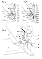
- the bed retractable according to the present invention is an independent assembly constituting a retractable mezzanine.
- This mezzanine consists of a frame 10 formed of four poles vertical 11 connected together by a rigid structure 12, 13, 14, for example triangulated, ensuring the stability and rigidity of the whole.
- This frame 10 serves to support a horizontal frame 20 formed normally of two longitudinal boxes 21 connected by two transverse boards 22, as indicated in FIG. 2 where the faces of the boxes 21 hiding in this view the retraction mechanism are not shown.
- Frame 20 could also be formed by two transverse boxes connected by two boards by changing the location of the retraction mechanisms in consequently, as will be apparent from the following explanations.
- the frame 20 could be formed by a box and a beam corresponding to the second box, these two pieces being of again connected by two boards.
- Each box 21 of the frame 20 contains a retraction mechanism 30 having two axes 31, as shown in Figure 3 where the outer face interior of the caissons is not shown to show the details of the mechanism 30.
- An axle 31 of a retraction mechanism 30 may physically crossing the entire frame 20 by connecting two mechanisms 30 in the boxes 21 located on each side of the frame 20 or can only have the length corresponding to the thickness of a box 21. From preferably, at least one of the two axes 31 of a retraction mechanism 30 crosses the frame 20, as shown in Figure 3.
- Each of these axes 31 is connected at its outer ends by a connecting rod 32 to a pivot 33 that includes each post 11 of the frame 10.
- the location of the pivot 33 in the posts 11 and the the length of the rods 32 are chosen so that, on the one hand, the position of storage of the frame 20 free space enough to use the place below this frame 20 and that, on the other hand, the position of use of the bed and in particular frame 20 is at a suitable height.
- the device can also be equipped with a ladder 23 allowing the user to climb into the bed without any effort, as shown in Figure 1b.
- Each axis 31 of the retraction mechanism 30 of each box 21 carries at least one rod 34, the ends of the two rods 34 of the two axes 31 being articulated on arms 35 to form a parallelogram deformable device imposing a synchronized rotation of the two axes 31.
- two opposite sides, longitudinal or transverse, of the frame 20 are equipped of a retraction mechanism 30, that is to say that arms 35 are thus in two boxes 21 located on two opposite sides of the frame 20.
- the second caisson can be replaced by a simple beam, as mentioned above, this beam not comprising that a pivot 33 connected by a connecting rod 32 to the axis 31 instead of a mechanism full retraction 30.
- the system retraction of a frame 20 has two retraction mechanisms 30 and is therefore symmetrical.
- the rods 34 are preferably mounted perpendicularly to the corresponding rod 32, as shown in Figure 3, and the arms 35 comprise, at each of their ends, an arcuate portion rounding the corners of the deformable parallelogram to allow the maximum bringing the arms 35 into the horizontal position of the rod 34, that is to say in the storage position 20a and use 20b of the frame 20, where the articulation links between the links 34 and the arms 35 must find the place between the two corresponding arms.
- This set of rods 34 and arm 35 forms a mechanism for synchronizing the movement of the axes 31.
- a variant among several others, not shown, to the solution previous to form such a motion synchronization mechanism has at least one pinion on each axis 31, these pinions being connected by a chain to form a kinematic connection imposing a rotation synchronized two axes 31. It is obvious that the pinion and chain assembly is equivalent to the mechanism using rods 34 and arms 35, and the remarks in the previous paragraph apply in a similar way to this solution.
- the motion synchronization mechanism that is positioned on the axes 31 and connects these two axes 31 by imposing a synchronized rotation of the two axes 31 is part of the retraction mechanism 30 and can be realized In a different way.
- Each axis 31 of the retraction mechanism 30 of each box 21 can still carry at least one sector 36, the two sectors 36 of a mechanism 30 being connected by one or more springs 37.
- the force of the springs 37 assists the up and down the downward movement of the frame 20.
- the force of the springs 37 can be adjusted through the aforementioned sectors 36 because the springs 37 or corresponding intermediate links, for example a wire 371 between a sector 36 and a spring 37, can be hooked to several places along the outer perimeter of each sector 36 thus putting the springs 37 under a more or less strong tension and simultaneously allowing change the angle of attack of a spring.
- One or even both sectors 36 can also be replaced by a simple lever by limiting or even removing the possibility of varying the torque exerted by the springs 37 on the sectors 36. set of sectors and springs thus plays the role of a training device for the retraction mechanism to facilitate the movement of the frame by the user. In order to cite an alternative solution, this provision could be replaced for example by spiral springs mounted individually on the axes 31.
- Figures 4a to 4c show in detail one of the embodiments possible of such a sector 36 on which is engaged a wire 371 connecting it to the spring corresponding 37.
- this sector 36 Along the outer periphery of this sector 36 are arranged several holes 361 for inserting a stop pin 362 on which the above-mentioned wire 371 is fixed, this being represented in FIG. 4a.
- the tension exerted on the spring 37 as well as its angle of attack with respect to the sector 36 can be set.
- orifices 211 are provided in the inner planks of the boxes 21 of a frame 20, for example in front of the holes 361 of the sector 36, the frame 20 being in the position of storage 20a. These orifices 211 and the pins 362 and 363 are illustrated in the FIG. 4c, the extension peg 363 being shown in its position cleared and in the engaged position.
- the connecting rods 32, the rods 34 and, where appropriate, the sectors 36 are fixed rigidly by in relation to others and preferably also to these axes. also be attached to the frame 31. in which the rods 32. the rods 34 and the where appropriate the sectors 36 are fixed rigidly relative to one another and the axes 31 rotated face on this set.
- pivots 33 which are pivotally mounted either in the rods 32 or in posts 11 (or both).
- the device may further comprise a locking device allowing to lock the frame 20 in at least one of its extreme positions.
- This locking device can be integrated in the axes 31, as illustrated in FIGS. Figures 5a and 5b.
- an axis 31 of a retraction mechanism is this effect achieved by a tube of a length corresponding approximately to the thickness of a box 21 and pivotally mounted in the frame 20 forming a rigid assembly with the rod 32, the link 34 and, where appropriate, the sector 36.
- this axis 31 is housed a cylindrical body 311, a tube or a cylinder, a slightly longer length than the axis 31.
- the body 311 is cut into bevel at the outer end facing the post 11 of the frame 10 and comprises a pin 312 at the inner end.
- a guide 313 with grooves receiving the pin 312 of the body 311 is fixed to the frame 20 so as to constrain the movement of the body 311 in the axis 31 forward and backward by preventing simultaneously its rotation.
- At least one spring 314 makes it possible to push the body 311 to the outside, the latter being able to retract inside the frame 20 when its outer end cut bevel touches the post 11.
- the latter is equipped with at least one stop, for example in the form of a striker 111 formed in the pole in front of the positions where the body 311 comes in the low position and / or high of the frame 20.
- the body 311 can snap into the striker 111 in the post, thereby locking the frame 20 in its storage position at the top or the use position at the bottom.
- the locking device can also placed elsewhere in the box 21, instead of being placed in the axis 31, while remaining able to cooperate with the frame 10.
- this locking device can be provided for example at the front part of the bed, preferably on each side, the front axle is therefore physically in two parts, while the rear axis of the bed can be in one piece to better synchronize frame movement physically connecting the two retraction mechanisms 30 housed in two boxes 21 on each side of the frame 20.
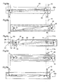
- a damping device 38 may be provided on the frame 20 or on the frame 10. As shown in FIG. 5a, this damping device 38 can be constituted by a hydraulic stop positioned inside a box 21 of so that it cooperates with the retraction mechanism 30, for example a sector 36, for damping the frame 20 driven in the upper position 20a by the springs 37. It could also be constituted by a spring, a rubber OR any other means capable of fulfilling this depreciation function, and the cooperation could be done with the rod 34, the connecting rod 32 or another piece of the mechanism of retraction 30.
- FIG. 6a shows the frame 20 in the high position, that is to say in the storage position 20a.
- the frame is locked again if equipped with the locking device described above. he It should be noted that during this movement the springs 37 are stretched compensating the weight of the frame 20 and allowing easy and smooth movement.
- the force exerted by the springs 37 increases from the position of storage 20a to become maximum in the intermediate position of the figure 6d and then decrease slightly to the position of use 20b. She can be adjusted using the aforementioned sectors 36 and pegs 362, 363, forming a mechanism for adjusting the force of the springs 37.
- the frame 20 can serve as a support for a bed base and a mattress for constitute a retractable mezzanine.
- the dimensions of frame 20 depend the size of the desired bed and can for example correspond to a single bed or a bed double.
- the length of the connecting rods 32 and the location of the pivots 33 of these two frames 20 are preferably selected in such a way that the storage positions 20a of the two frames 20 are relatively close to each other while the positions 20b are similar to the positions of the bunk bed bases normal.
- the movement plans of the rods 32 of the two frames 20 must be slightly offset to allow the connecting rod 32 of the frame can pass the pivot 33 of the high frame.
- the Murphy bed in mezzanine is characterized primarily by the characteristics following: It presents a frame, this frame being equipped with a frame. A mechanism allows to retract the frame from a first low position of use to a second high storage position.
- the mechanism positioned on the frame, comprises two axes, each of these axes being connected by a connecting rod to a pivot on the frame, in order to connect the frame and the frame. It still has a mechanism for synchronization of the movement connecting these two axes and imposing a rotation synchronized of the two axes.
- This mechanism of motion synchronization can be achieved by at least one rod on each axis, these rods being articulated on arms to form a deformable parallelogram imposing a synchronized rotation of the two axes.
- the retraction mechanism also includes, on these axes, at least one sector and a lever or two sectors, these being connected by one or more springs in order to have a drive device to provide a force facilitating the movement of a position to the other of the frame.
- the device according to the present invention thus makes available a piece of furniture transformable that can be used as bed at night in its position of use and occupying little space during the day in its storage position, this goal being completed in a simple, efficient and inexpensive way thanks to the characteristics above.
Landscapes
- Health & Medical Sciences (AREA)
- General Health & Medical Sciences (AREA)
- Nursing (AREA)
- Invalid Beds And Related Equipment (AREA)
- Orthopedics, Nursing, And Contraception (AREA)
- Accommodation For Nursing Or Treatment Tables (AREA)
Abstract
Description
La présente invention a pour objet un dispositif servant de lit escamotable en mezzanine comportant un bâti équipé d'un cadre, un mécanisme d'escamotage permettant d'escamoter le cadre de lit d'une première position d'utilisation à une deuxième position de rangement.The subject of the present invention is a device serving as a retractable bed mezzanine comprising a frame equipped with a frame, a retraction mechanism retracting the bed frame from a first use position to a second storage position.
En général, on connaít ce genre de dispositifs dont le but est de mettre à disposition un meuble transformable. Ainsi, le meuble peut être utilisé dans une première position pour ensuite être transformé dans sa deuxième position afin de libérer de l'espace. Dans le cas présent, le meuble peut servir de lit pendant la nuit pour être transformé pendant la journée afin de disposer de plus d'espace dans la pièce.In general, we know what kind of devices whose purpose is to put in provision a furniture transformable. Thus, the furniture can be used in a first position to then be transformed into his second position in order to free up space. In this case, the furniture can serve as bed during the night to be transformed during the day in order to have more space in the room.
Le document FR 2 729 062 décrit notamment un lit escamotable composé d'un bâti, d'un cadre et d'un mécanisme permettant de positionner le cadre horizontal à plusieurs positions en hauteur, le lit pouvant ainsi être utilisé ou rangé. Le mécanisme d'escamotage utilisé dans ce cas fonctionne à l'aide de moyens d'entraínement électriques comportant notamment un moteur.The document FR 2 729 062 describes in particular a retractable bed composed of a frame, a frame and a mechanism to position the frame horizontally at several positions in height, the bed can be used or stored. The retraction mechanism used in this case works by means of electric drives comprising in particular a motor.
Un dispositif similaire est exposé dans le document CH 678 145, le bâti servant de support étant dans ce cas fixé au plafond de la pièce destinée à être équipée avec le meuble transformable.A similar device is disclosed in document CH 678 145, the frame used as a support being in this case fixed to the ceiling of the room intended to be equipped with transformable furniture.
Ces dispositifs font recours à des moyens d'entraínement électriques nécessitant un agencement correspondant du meuble notamment pour héberger le moteur et pour amener du courant pour son fonctionnement. Au niveau esthétique et en ce qui concerne la place prise par ces moyens, ceci a des conséquences défavorables, surtout dans le cas d'un meuble servant de lit. Le fait de recourir à des moyens électriques limite les possibilités d'installation et d'utilisation d'un tel meuble. De même, le fait de fixer le bâti au plafond d'une pièce enlève de la flexibilité d'utilisation du meuble. En plus, les coûts de production et les risques de panne pour ce type de mécanisme d'escamotage sont relativement élevés.These devices make use of electrical drive means requiring a corresponding arrangement of the furniture, especially to house the motor and to bring current for its operation. At the level aesthetic and with regard to the place taken by these means, this has adverse consequences, especially in the case of bed furniture. The fact use of electrical means limits the possibilities of installation and of use of such a piece of furniture. Similarly, fixing the frame to the ceiling of a piece removes the flexibility of use of the furniture. In addition, the costs of production and the risks of failure for this type of retraction mechanism are relatively high.
Le but de la présente invention est de réaliser un dispositif tendant à obvier aux inconvénients précités des systèmes actuels.The object of the present invention is to provide a device tending to obviate the aforementioned drawbacks of current systems.
La présente invention a pour objet un dispositif servant de lit escamotable en mezzanine comprenant les caractéristiques énoncées à la revendication 1.The subject of the present invention is a device serving as a retractable bed a mezzanine comprising the features set forth in claim 1.
En particulier, le mécanisme d'escamotage du dispositif comporte deux axes positionnés sur un cadre de lit, chacun de ces axes étant relié par une bielle à un pivot sur un bâti, afin de relier le cadre et le bâti, et un mécanisme de synchronisation du mouvement reliant ces deux axes et imposant une rotation synchronisée des deux axes.In particular, the mechanism of retraction of the device comprises two axes positioned on a bed frame, each of these axes being connected by a connecting rod to a pivot on a frame, in order to connect the frame and the frame, and a mechanism of synchronization of the movement connecting these two axes and imposing a rotation synchronized of the two axes.
Dans une forme d'exécution, le mécanisme d'escamotage comporte au moins une biellette sur chaque axe, ces biellettes étant articulées sur des bras pour former un parallélogramme déformable imposant une rotation synchronisée des deux axes.In one embodiment, the retraction mechanism comprises at least one minus one link on each axis, these links being articulated on arms to form a deformable parallelogram imposing a synchronized rotation both axes.
Il est ainsi possible de réaliser un moyen d'escamotage mécanique simple ne faisant pas recours à des moyens électriques. Le mécanisme est agencé, en réduisant le nombre de pièces et en optimisant leur emplacement, de manière efficace et simple afin de réduire les coûts de production et l'entretien. Il peut être facilement installé à l'intérieur d'un caisson intégré naturellement dans le cadre supportant le sommier du lit afin de disposer d'une présentation esthétiquement attractive du meuble.It is thus possible to achieve a simple mechanical retraction means not using electrical means. The mechanism is arranged, in reducing the number of parts and optimizing their location, so efficient and simple to reduce production costs and maintenance. He can be easily installed inside a box integrated naturally in the frame supporting the bedspring of the bed in order to have a presentation aesthetically attractive furniture.
De plus, le mécanisme peut comporter au moins un secteur et un levier ou deux secteurs positionnés sur les axes, ceux-ci étant reliés par un ou plusieurs ressorts. Le ressort fournit une force facilitant le déplacement d'une position du cadre à l'autre. Disposant ainsi d'un confort d'utilisation comparable à celui d'un moyen électrique, l'espace nécessaire pour héberger le mécanisme d'escamotage peut en même temps être réduit en améliorant l'esthétique et aussi la flexibilité d'utilisation du meuble. In addition, the mechanism may include at least one sector and a lever or two sectors positioned on the axes, these being connected by one or more springs. The spring provides a force facilitating the displacement of a position of the frame to another. Thus having a comfort of use comparable to that of a electrical means, the space required to house the retraction mechanism can at the same time be reduced by improving aesthetics and also flexibility of use of the furniture.
Ainsi, le meuble transformable selon la présente invention peut servir de lit dans sa position d'utilisation et permet de libérer facilement de l'espace dans sa position de rangement, par exemple pour se servir d'un bureau, d'une table ou d'autres choses installé sous le cadre du lit.Thus, the transformable furniture according to the present invention can serve as a bed in its use position and makes it easy to clear space in its storage position, for example to use a desk, table or other things installed under the bed frame.
D'autres avantages ressortent des caractéristiques exprimées dans les revendications dépendantes et de la description exposant ci-après l'invention plus en détail à l'aide de dessins.Other advantages emerge from the characteristics expressed in the dependent claims and description hereafter disclosing the invention more in detail using drawings.
Les dessins annexés représentent, schématiquement et à titre d'exemple,
une forme d'exécution de l'invention.
L'invention va maintenant être décrite en détail en référence aux dessins annexés qui illustrent à titre d'exemple une forme d'exécution de l'invention. The invention will now be described in detail with reference to the drawings appended which illustrate by way of example an embodiment of the invention.
En référence aux figures 1a et 1b, on remarque d'abord que le lit escamotable selon la présente invention est un ensemble indépendant constituant une mezzanine escamotable.With reference to FIGS. 1a and 1b, it is firstly noted that the bed retractable according to the present invention is an independent assembly constituting a retractable mezzanine.
Cette mezzanine se compose d'un bâti 10 formé de quatre poteaux
verticaux 11 reliés ensembles par une structure rigide 12, 13, 14, par exemple
triangulée, assurant la stabilité et la rigidité de l'ensemble.This mezzanine consists of a
Ce bâti 10 sert de support à un cadre horizontal 20 formé normalement de
deux caissons longitudinaux 21 reliés par deux planches transversales 22, comme
indiqué à la figure 2 où les faces des caissons 21 cachant dans cette vue le
mécanisme d'escamotage ne sont pas représentées. Le cadre 20 pourrait
également être formé par deux caissons transversaux reliés par deux planches
longitudinales, en modifiant l'emplacement des mécanismes d'escamotage en
conséquence, comme il ressortira des explications suivantes. Dans une autre
forme d'exécution faisant recours à un mécanisme d'escamotage plus simple et
asymétrique, le cadre 20 pourrait être formé par un caisson et une poutre
correspondante remplaçant le deuxième caisson, ces deux pièces étant de
nouveau reliées par deux planches.This
Chaque caisson 21 du cadre 20 renferme un mécanisme d'escamotage 30
comportant deux axes 31, comme le montre la figure 3 où la face extérieure
respectivement intérieure des caissons n'est pas représentée afin de montrer les
détails du mécanisme 30. Un axe 31 d'un mécanisme d'escamotage 30 peut
traverser physiquement tout le cadre 20 en reliant deux mécanismes
d'escamotage 30 dans les caissons 21 situés de chaque côté du cadre 20 ou peut
n'avoir que la longueur correspondant à l'épaisseur d'un caisson 21. De
préférence, au moins un des deux axes 31 d'un mécanisme d'escamotage 30
traverse le cadre 20, comme le montre la figure 3. Chacun de ces axes 31 est relié
à ses extrémités extérieures par une bielle 32 à un pivot 33 que comporte chaque
poteau 11 du bâti 10. L'emplacement du pivot 33 dans les poteaux 11 ainsi que la
longueur des bielles 32 sont choisis de façon à ce que, d'une part, la position de
rangement du cadre 20 libère suffisamment d'espace pour pouvoir utiliser la place
en dessous de ce cadre 20 et que, d'autre part, la position d'utilisation du lit et
notamment du cadre 20 se trouve à une hauteur convenable. Le dispositif peut
aussi être équipé d'une échelle 23 permettant à l'utilisateur de monter dans le lit
sans aucun effort, comme le montre la figure 1b.Each
Chaque axe 31 du mécanisme d'escamotage 30 de chaque caisson 21
porte au moins une biellette 34, les extrémités des deux biellettes 34 des deux
axes 31 étant articulées sur des bras 35 pour former un parallélogramme
déformable imposant une rotation synchronisée des deux axes 31. De préférence,
deux côtés opposés, soit longitudinal ou transversal, du cadre 20 sont équipés
d'un mécanisme d'escamotage 30, c'est-à-dire que des bras 35 se trouvent ainsi
dans deux caissons 21 situés sur deux côtés opposés du cadre 20. Dans le cas
d'un système d'escamotage asymétrique, le deuxième caisson peut être remplacé
par une simple poutre, comme mentionné ci-dessus, cette poutre ne comportant
qu'un pivot 33 relié par une bielle 32 à l'axe 31 au lieu d'un mécanisme
d'escamotage 30 complet. Dans le cas préféré de deux caissons 21, le système
d'escamotage d'un cadre 20 comporte deux mécanismes d'escamotage 30 et est
donc symétrique. Les biellettes 34 sont de préférence montées perpendiculairement
à la bielle 32 correspondante, comme cela est illustré dans la figure 3, et
les bras 35 comportent, à chacune de leurs extrémités, une partie arquée
arrondissant les coins du parallélogramme déformable afin de permettre le
rapprochement maximal des bras 35 dans la position horizontale de la biellette 34,
c'est-à-dire dans la position de rangement 20a et d'utilisation 20b du cadre 20, où
les liaisons d'articulation entre les biellettes 34 et les bras 35 doivent trouver la
place entre les deux bras 35 correspondants. Cet ensemble de biellettes 34 et de
bras 35 forme un mécanisme de synchronisation du mouvement des axes 31.Each
Une variante entre plusieurs autres, non représentée, à la solution
précédente pour former un tel mécanisme de synchronisation du mouvement
comporte au moins un pignon sur chaque axe 31, ces pignons étant reliés par une
chaíne pour former une connexion cinématique imposant une rotation
synchronisée des deux axes 31. Il est évident que l'ensemble pignon et chaíne est
équivalent au mécanisme utilisant des biellettes 34 et des bras 35, et les
remarques du paragraphe précédent s'appliquent de façon analogue à cette
solution.A variant among several others, not shown, to the solution
previous to form such a motion synchronization mechanism
has at least one pinion on each
Le mécanisme de synchronisation du mouvement qui est positionné sur les
axes 31 et relie ces deux axes 31 en imposant une rotation synchronisée des
deux axes 31 fait partie du mécanisme d'escamotage 30 et peut ainsi être réalisé
de façon différente.The motion synchronization mechanism that is positioned on the
Après cette description de la liaison entre le cadre 20 et le bâti 10 voir du
mécanisme d'escamotage 30, il est clair que les positions d'utilisation 20b et de
rangement 20a du cadre 20 se trouvent, pour le dispositif selon la présente
invention, d'un côté et de l'autre des axes 33a de pivotement du cadre 20, c'est-à-dire
des pivots 33 du bâti.After this description of the connection between the
Chaque axe 31 du mécanisme d'escamotage 30 de chaque caisson 21
peut encore porter au moins un secteur 36, les deux secteurs 36 d'un mécanisme
30 étant reliés par un ou plusieurs ressorts 37. La force des ressorts 37 aide à la
remontée et amortit le mouvement descendant du cadre 20. La force des ressorts
37 peut être ajustée par l'intermédiaire des secteurs 36 susmentionnés du fait que
les ressorts 37 ou des liaisons intermédiaires correspondantes, par exemple un fil
371 entre un secteur 36 et un ressort 37, peuvent être accrochés à plusieurs
endroits le long du pourtour extérieur de chaque secteur 36 mettant ainsi les
ressorts 37 sous une tension plus ou moins forte et permettant simultanément de
modifier l'angle d'attaque d'un ressort. Un, voire même les deux secteurs 36
peuvent aussi être remplacés par un simple levier en limitant, voire supprimant la
possibilité de varier le couple exercé par les ressorts 37 sur les secteurs 36. Cet
ensemble de secteurs et ressorts joue donc le rôle d'un dispositif d'entraínement
pour le mécanisme d'escamotage afin de faciliter le mouvement du cadre par
l'utilisateur. Afin de citer une solution alternative, cette disposition pourrait être
remplacée par exemple par des ressorts spiraux montés individuellement sur les
axes 31.Each
Les figures 4a à 4c montrent en détail une des formes d'exécution
possibles d'un tel secteur 36 sur lequel est engagé un fil 371 le reliant au ressort
correspondant 37. Le long du pourtour extérieur de ce secteur 36 sont agencés
plusieurs trous 361 permettant d'y introduire une cheville d'arrêt 362 sur laquelle
est fixé le fil 371 susmentionné, ceci étant représenté à la figure 4a. En modifiant
l'emplacement de la cheville d'arrêt 362 sur le pourtour du secteur, la tension
exercée sur le ressort 37 ainsi que son angle d'attaque par rapport au secteur 36
peuvent être réglés. A l'aide d'une cheville de prolongement 363 introduite en plus
de la cheville d'arrêt dans un autre trou 361 le long du pourtour de ce secteur 36
et en faisant passer le fil 371 sur cette cheville de prolongement 363, la tension du
ressort 37 peut encore être renforcée tout en modifiant l'angle d'attaque comme
avant, cette disposition étant illustrée à la figure 4b. Il existe aussi d'autres
moyens pour réaliser le réglage de la tension, par exemple en enroulant le fil 371
sur la cheville d'arrêt 362 en tournant cette dernière qui peut à cet effet être
agencée sous forme d'une vis. Pour l'introduction facile des chevilles 362 et/ou
363 et un réglage plus facile une fois le lit étant monté, des orifices 211 sont
prévus dans les planches intérieures des caissons 21 d'un cadre 20, par exemple
en face des trous 361 du secteur 36, le cadre 20 étant dans la position de
rangement 20a. Ces orifices 211 et les chevilles 362 et 363 sont illustrés dans la
figure 4c, la cheville de prolongement 363 étant montrée dans sa position
dégagée et dans la position engagée.Figures 4a to 4c show in detail one of the embodiments
possible of such a
Il existe notamment plusieurs possibilités de montage relatif des pièces du
mécanisme d'escamotage 30. Si les axes 31 sont montés face, dans le cadre 20,
par exemple à l'aide de roulements ou des simples ouvertures, les bielles 32, les
biellettes 34 et, le cas échéant, les secteurs 36 sont fixés rigidement les uns par
rapport aux autres et de préférence aussi à ces axes 31. Les axes 31 peuvent
aussi être fixés au cadre 31. cas dans lequel les bielles 32. les biellettes 34 et le
cas échéant les secteurs 36 sont fixés rigidement les uns par rapport aux autres et
les axes 31 pivotés face sur cet ensemble. Une remarque similaire s'applique aux
pivots 33 qui sont montés de manière pivotante soit dans les bielles 32 soit dans
les poteaux 11 (voire les deux).In particular, there are several possibilities for relative mounting of parts of the
30. If the
Le dispositif peut encore comporter un dispositif de verrouillage permettant
de verrouiller le cadre 20 dans au moins une de ses positions extrêmes. Ce
dispositif de verrouillage peut être intégré dans les axes 31, comme illustré aux
figures 5a et 5b. De préférence, un axe 31 d'un mécanisme d'escamotage est à
cet effet réalisé par un tube d'une longueur correspondant environ à l'épaisseur
d'un caisson 21 et monté de façon pivotante dans le cadre 20 en formant un
ensemble rigide avec la bielle 32, la biellette 34 et, le cas échéant, le secteur 36.
Dans cet axe 31 vient se loger un corps cylindrique 311, un tube ou un cylindre,
d'une longueur légèrement plus élevée que l'axe 31. Le corps 311 est coupé en
biseau à l'extrémité extérieure orientée vers le poteau 11 du bâti 10 et comporte
une goupille 312 à l'extrémité intérieure. Un guide 313 comportant des rainures
recevant la goupille 312 du corps 311 est fixé au cadre 20 de façon à contraindre
le mouvement du corps 311 dans l'axe 31 en avant et en arrière en empêchant
simultanément sa rotation. Au moins un ressort 314 permet de pousser le corps
311 vers l'extérieur, celui-ci pouvant se rétracter à l'intérieur du cadre 20 quand
son extrémité extérieure coupée en biseau vient toucher le poteau 11. Ce dernier
est équipé d'au moins un arrêt, par exemple sous forme d'une gâche 111 formée
dans le poteau en face des positions où vient le corps 311 dans la position basse
et/ou haute du cadre 20. Sous l'effet de la force du ou des ressorts 314, le corps
311 peut s'encliqueter dans la gâche 111 dans le poteau, verrouillant ainsi le
cadre 20 dans sa position de rangement en haut ou la position d'utilisation en bas.
En retirant le corps 311, par exemple à l'aide d'une cordelette 315, le cadre 20
peut de nouveau être déverrouillé. Le dispositif de verrouillage peut également
être placé ailleurs dans le caisson 21, au lieu d'être placé dans l'axe 31, tout en
restant apte à coopérer avec le bâti 10. En général, ce dispositif de verrouillage
peut être prévu par exemple à la partie avant du lit, de préférence de chaque côté,
l'axe avant étant donc physiquement en deux parties, tandis que l'axe arrière du lit
peut être en une pièce afin de servir à mieux synchroniser le mouvement du cadre
en reliant physiquement les deux mécanismes d'escamotage 30 logé dans deux
caissons 21 de chaque côté du cadre 20.The device may further comprise a locking device allowing
to lock the
De plus, un dispositif d'amortissement 38 peut être prévu sur le cadre 20 ou
sur le bâti 10. Comme le montre la figure 5a, ce dispositif d'amortissement 38 peut
être constitué par un arrêt hydraulique positionné à l'intérieur d'un caisson 21 de
manière à ce qu'il coopère avec le mécanisme d'escamotage 30, par exemple un
secteur 36, pour amortir le cadre 20 entraíné en position haute 20a par les
ressorts 37. Il pourrait également être constitué par un ressort, un caoutchouc OU
tout autre moyen apte à remplir cette fonction d'amortissement, et la coopération
pourrait se faire avec la biellette 34, la bielle 32 ou une autre pièce du mécanisme
d'escamotage 30.In addition, a damping
La suite des figures 6a à 6e permet d'expliquer le fonctionnement du
dispositif. La figure 6a montre le cadre 20 en position haute, c'est-à-dire dans la
position de rangement 20a. En tirant horizontalement, éventuellement après avoir
déverrouillé le cadre 20 à l'aide de la cordelette 315, sur une des planches
transversales 22, qui peut à cet effet comporter des ouvertures servant de
poignée, le cadre 20 se déplace, tout en restant horizontal, vers l'avant et le bas,
les positions intermédiaires du cadre 20 étant illustrées aux figures 6b et 6c, puis
vers l'arrière et vers le bas, voir la figure 6d, pour finir son déplacement en position
basse d'utilisation 20b illustrée à la figure 6e. Dans cette position, le cadre est à
nouveau verrouillé s'il est équipé du dispositif de verrouillage décrit ci-dessus. Il
est à remarquer que pendant ce déplacement les ressorts 37 se tendent
compensant le poids du cadre 20 et permettant un déplacement aisé et sans à-coup.
La force exercée par les ressorts 37 augmente à partir de la position de
rangement 20a pour devenir maximale dans la position intermédiaire de la figure
6d et diminuer ensuite légèrement jusqu'à la position d'utilisation 20b. Elle peut
être ajustée à l'aide des secteurs 36 et des chevilles 362, 363 susmentionnés,
formant un mécanisme de réglage de la force des ressorts 37.The sequence of FIGS. 6a to 6e explains the operation of the
device. FIG. 6a shows the
En tirant à nouveau sur la planche transversale 22, on repasse de la
position basse illustrée à la figure 6e à la position haute du cadre 20 illustrée à la
figure 6a. Pour ce mouvement ascendant, la force des ressorts 37 aide à la
remontée du cadre de sorte que la force nécessaire pour ce relevage est minime,
voire que le cadre est auto-montant de par la force des ressorts qui peut
également, à la place du dispositif de verrouillage, tenir le cadre en position
haute.. Proche de la position de rangement 20a, le dispositif d'amortissement
permet d'amortir le mouvement du cadre 20 entraíné par la force des ressorts 37
en s'appliquant par exemple sur les secteurs 36 du mécanisme d'escamotage 30,
comme illustré à la figure 6a.By pulling again on the
Le cadre 20 peut servir de support à un sommier et un matelas pour
constituer une mezzanine escamotable. Les dimensions du cadre 20 dépendent
de la taille du lit souhaité et peut par exemple correspondre à un lit simple ou un lit
double.The
Il est également possible de prévoir deux cadres 20 sur le bâti 10 afin de
disposer d'un lit superposé escamotable. Dans ce cas, la longueur des bielles 32
et l'emplacement des pivots 33 de ces deux cadres 20 sont choisis de préférence
de manière à ce que les positions de rangement 20a des deux cadres 20 se
trouvent assez rapprochées l'une par rapport à l'autre tandis que les positions
d'utilisation 20b sont similaires aux positions des sommiers de lits superposés
normal. Dans ce cas, les plans de mouvement des bielles 32 des deux cadres 20
doivent être légèrement décalés afin de permettre que la bielle 32 du cadre bas
puisse passer le pivot 33 du cadre haut.It is also possible to provide two
En résumé, il est à noter que le lit escamotable en mezzanine selon la présente invention est caractérisé principalement par les caractéristiques suivantes: Il présente un bâti, ce bâti étant équipé d'un cadre. Un mécanisme permet d'escamoter le cadre d'une première position basse d'utilisation à une deuxième position haute de rangement. Le mécanisme, positionné sur le cadre, comporte deux axes, chacun de ces axes étant relié par une bielle à un pivot sur le bâti, afin de relier le cadre et le bâti. Il comporte encore un mécanisme de synchronisation du mouvement reliant ces deux axes et imposant une rotation synchronisée des deux axes. Ce mécanisme de synchronisation du mouvement peut être réalisé par au moins une biellette sur chaque axe, ces biellettes étant articulées sur des bras pour former un parallélogramme déformable imposant une rotation synchronisée des deux axes. De préférence, le mécanisme d'escamotage comporte aussi, également sur ces axes, au moins un secteur et un levier ou deux secteurs, ceux-ci étant reliés par un ou plusieurs ressorts afin de disposer d'un dispositif d'entraínement pour fournir une force facilitant le déplacement d'une position à l'autre du cadre.In summary, it should be noted that the Murphy bed in mezzanine according to the The present invention is characterized primarily by the characteristics following: It presents a frame, this frame being equipped with a frame. A mechanism allows to retract the frame from a first low position of use to a second high storage position. The mechanism, positioned on the frame, comprises two axes, each of these axes being connected by a connecting rod to a pivot on the frame, in order to connect the frame and the frame. It still has a mechanism for synchronization of the movement connecting these two axes and imposing a rotation synchronized of the two axes. This mechanism of motion synchronization can be achieved by at least one rod on each axis, these rods being articulated on arms to form a deformable parallelogram imposing a synchronized rotation of the two axes. Preferably, the retraction mechanism also includes, on these axes, at least one sector and a lever or two sectors, these being connected by one or more springs in order to have a drive device to provide a force facilitating the movement of a position to the other of the frame.
Le dispositif selon la présente invention met ainsi à disposition un meuble transformable pouvant servir de lit la nuit dans sa position d'utilisation et occupant peu d'espace durant la journée dans sa position de rangement, ce but étant achevé de façon simple, efficace et peu coûteuse grâce aux caractéristiques susmentionnées.The device according to the present invention thus makes available a piece of furniture transformable that can be used as bed at night in its position of use and occupying little space during the day in its storage position, this goal being completed in a simple, efficient and inexpensive way thanks to the characteristics above.
Claims (12)
Priority Applications (5)
| Application Number | Priority Date | Filing Date | Title |
|---|---|---|---|
| DE60323976T DE60323976D1 (en) | 2003-09-18 | 2003-09-18 | Extendable platform bed |
| EP03021084A EP1516567B1 (en) | 2003-09-18 | 2003-09-18 | Retractable mezzanine bed |
| AT03021084T ATE410099T1 (en) | 2003-09-18 | 2003-09-18 | EXTENDABLE PLATFORM BED |
| PCT/IB2004/002459 WO2005025380A1 (en) | 2003-09-18 | 2004-07-20 | Stowable mezzanine bed |
| US10/572,392 US7552486B2 (en) | 2003-09-18 | 2004-07-20 | Stowable mezzanine bed |
Applications Claiming Priority (1)
| Application Number | Priority Date | Filing Date | Title |
|---|---|---|---|
| EP03021084A EP1516567B1 (en) | 2003-09-18 | 2003-09-18 | Retractable mezzanine bed |
Publications (2)
| Publication Number | Publication Date |
|---|---|
| EP1516567A1 true EP1516567A1 (en) | 2005-03-23 |
| EP1516567B1 EP1516567B1 (en) | 2008-10-08 |
Family
ID=34178430
Family Applications (1)
| Application Number | Title | Priority Date | Filing Date |
|---|---|---|---|
| EP03021084A Expired - Lifetime EP1516567B1 (en) | 2003-09-18 | 2003-09-18 | Retractable mezzanine bed |
Country Status (5)
| Country | Link |
|---|---|
| US (1) | US7552486B2 (en) |
| EP (1) | EP1516567B1 (en) |
| AT (1) | ATE410099T1 (en) |
| DE (1) | DE60323976D1 (en) |
| WO (1) | WO2005025380A1 (en) |
Families Citing this family (8)
| Publication number | Priority date | Publication date | Assignee | Title |
|---|---|---|---|---|
| US7874026B2 (en) * | 2007-08-24 | 2011-01-25 | Double Space Bed Systems, Inc. | System and method for raising and lowering a bed |
| US8856982B1 (en) * | 2010-07-13 | 2014-10-14 | Christopher George Kalivas | Motion bed |
| US11134787B2 (en) | 2018-05-16 | 2021-10-05 | Bestar Inc. | Anti-shearing and anti-crushing device on a retractable bed |
| USD880185S1 (en) * | 2018-11-09 | 2020-04-07 | Ori Inc. | Furniture item |
| USD880174S1 (en) * | 2018-11-09 | 2020-04-07 | Ori Inc. | Furniture item |
| CA3120146A1 (en) * | 2020-05-15 | 2021-11-15 | Bestar Inc. | Automated safety locking device for wall beds |
| USD1015002S1 (en) * | 2021-06-28 | 2024-02-20 | Comptree, Inc. | Loft bed |
| CN114164980B (en) * | 2021-12-16 | 2023-09-29 | 四川润邦建材有限公司 | Multifunctional lifting type suspended ceiling |
Citations (3)
| Publication number | Priority date | Publication date | Assignee | Title |
|---|---|---|---|---|
| US3745595A (en) * | 1972-08-29 | 1973-07-17 | Kwikee Enterprises Inc | Suspension means for bunk beds |
| US3829912A (en) * | 1971-09-01 | 1974-08-20 | Flexsteel Industries | Retractable bed assemblies |
| FR2591876A1 (en) * | 1985-12-20 | 1987-06-26 | Avril Joel | Retractable bed device placed in a folding raised section of a vehicle or in a dwelling |
Family Cites Families (4)
| Publication number | Priority date | Publication date | Assignee | Title |
|---|---|---|---|---|
| IT1177944B (en) | 1984-07-31 | 1987-08-26 | Pietro Crocoli | RETRACTABLE RETRACTABLE BED |
| ES293860Y (en) | 1986-04-28 | 1987-05-16 | Fernandez Romero Juan | FOLDING BED-BED WITH SAFETY DEVICE |
| JPH07119Y2 (en) | 1988-03-18 | 1995-01-11 | 三和シヤッター工業株式会社 | Electric lifting bed |
| FR2729062A1 (en) | 1995-01-11 | 1996-07-12 | Dievart Rene Charles | Furniture or appliance with part that can be raised and lowered |
-
2003
- 2003-09-18 DE DE60323976T patent/DE60323976D1/en not_active Expired - Lifetime
- 2003-09-18 EP EP03021084A patent/EP1516567B1/en not_active Expired - Lifetime
- 2003-09-18 AT AT03021084T patent/ATE410099T1/en not_active IP Right Cessation
-
2004
- 2004-07-20 WO PCT/IB2004/002459 patent/WO2005025380A1/en active Application Filing
- 2004-07-20 US US10/572,392 patent/US7552486B2/en active Active
Patent Citations (3)
| Publication number | Priority date | Publication date | Assignee | Title |
|---|---|---|---|---|
| US3829912A (en) * | 1971-09-01 | 1974-08-20 | Flexsteel Industries | Retractable bed assemblies |
| US3745595A (en) * | 1972-08-29 | 1973-07-17 | Kwikee Enterprises Inc | Suspension means for bunk beds |
| FR2591876A1 (en) * | 1985-12-20 | 1987-06-26 | Avril Joel | Retractable bed device placed in a folding raised section of a vehicle or in a dwelling |
Also Published As
| Publication number | Publication date |
|---|---|
| ATE410099T1 (en) | 2008-10-15 |
| EP1516567B1 (en) | 2008-10-08 |
| US7552486B2 (en) | 2009-06-30 |
| US20070074342A1 (en) | 2007-04-05 |
| WO2005025380A1 (en) | 2005-03-24 |
| DE60323976D1 (en) | 2008-11-20 |
Similar Documents
| Publication | Publication Date | Title |
|---|---|---|
| EP1516567A1 (en) | Retractable mezzanine bed | |
| FR2786996A1 (en) | SEAT PROVIDED WITH AN ASSISTANCE DEVICE FOR STANDING UP | |
| EP0575243A1 (en) | Vehicle seat with multiple adjustment | |
| EP0077280B1 (en) | Lifting chair | |
| EP0231698B1 (en) | Folding seats for vehicles | |
| FR2548107A1 (en) | SEAT ADJUSTMENT DEVICE, PARTICULARLY FOR VEHICLE SEATS | |
| EP1627255A2 (en) | Masking device for a cinema screen | |
| EP1769954A1 (en) | Sun visor device for a vehicle's windshield, with a roller blind, and corresponding vehicle | |
| FR2474084A1 (en) | SUSPENDED BLIND DEVICE AND ROLLER FOR PRODUCING A CANOPY | |
| FR2891493A1 (en) | Anti-dazzle screen holder for motor vehicle, has cassette and draw bar stacked with respect to each other to form small anti-dazzle screen holder when sheet is folded, and balancing unit controlling bar to remain parallel to cassette | |
| EP1725138B1 (en) | Storage device | |
| FR3079729A1 (en) | PANEL FRAME (X) | |
| FR2931397A1 (en) | Occultation blind for glazed surface i.e. window pane, of motor vehicle door, has web whose edge is integrated to winding tube mounted around axle placed close to tube ends and perpendicular to plane of surface for folding or deploying web | |
| FR2918929A1 (en) | OCCULTATION STORAGE FOR A MOTOR VEHICLE, WITH A TILT BAR, AND A CORRESPONDING MOTOR VEHICLE | |
| EP3346072B1 (en) | Awning structure | |
| EP2183444A2 (en) | Single-bracket awning | |
| EP2955060A1 (en) | Retractable cabinet above a shower tray, allowing free access to the shower tray when in the retracted position | |
| FR2827005A1 (en) | Blind for motor vehicle has closure panel movable between deployed and retracted positions | |
| EP0319443B1 (en) | Venetian blind | |
| EP1530928A1 (en) | Collapsible chair seat with a low profile in the collapsed position | |
| EP0356295A1 (en) | Folding caravan with rigid panels comprising one or more items of roof furniture | |
| BE903832R (en) | Ladder with extendable sections - has sections locked by rack and pinion mechanism and operated manually or automatically | |
| WO2004023940A1 (en) | Retractable bed assembly | |
| FR2733274A1 (en) | Roller blind for railway carriages | |
| FR2927780A1 (en) | Sun-umbrella and windbreaker/complementary ergonomic backrest for e.g. relaxation in beach, has framework for supporting tarpaulin and axial windbreakers, where sun-umbrella and windbreaker/backrest is connected to external furniture |
Legal Events
| Date | Code | Title | Description |
|---|---|---|---|
| PUAI | Public reference made under article 153(3) epc to a published international application that has entered the european phase |
Free format text: ORIGINAL CODE: 0009012 |
|
| AK | Designated contracting states |
Kind code of ref document: A1 Designated state(s): AT BE BG CH CY CZ DE DK EE ES FI FR GB GR HU IE IT LI LU MC NL PT RO SE SI SK TR |
|
| AX | Request for extension of the european patent |
Extension state: AL LT LV MK |
|
| 17P | Request for examination filed |
Effective date: 20050906 |
|
| AKX | Designation fees paid |
Designated state(s): AT BE BG CH CY CZ DE DK EE ES FI FR GB GR HU IE IT LI LU MC NL PT RO SE SI SK TR |
|
| GRAP | Despatch of communication of intention to grant a patent |
Free format text: ORIGINAL CODE: EPIDOSNIGR1 |
|
| GRAS | Grant fee paid |
Free format text: ORIGINAL CODE: EPIDOSNIGR3 |
|
| GRAA | (expected) grant |
Free format text: ORIGINAL CODE: 0009210 |
|
| AK | Designated contracting states |
Kind code of ref document: B1 Designated state(s): AT BE BG CH CY CZ DE DK EE ES FI FR GB GR HU IE IT LI LU MC NL PT RO SE SI SK TR |
|
| REG | Reference to a national code |
Ref country code: GB Ref legal event code: FG4D Free format text: NOT ENGLISH |
|
| REG | Reference to a national code |
Ref country code: CH Ref legal event code: EP |
|
| REG | Reference to a national code |
Ref country code: IE Ref legal event code: FG4D Free format text: LANGUAGE OF EP DOCUMENT: FRENCH |
|
| REF | Corresponds to: |
Ref document number: 60323976 Country of ref document: DE Date of ref document: 20081120 Kind code of ref document: P |
|
| REG | Reference to a national code |
Ref country code: CH Ref legal event code: NV Representative=s name: MICHELI & CIE SA |
|
| PG25 | Lapsed in a contracting state [announced via postgrant information from national office to epo] |
Ref country code: SI Free format text: LAPSE BECAUSE OF FAILURE TO SUBMIT A TRANSLATION OF THE DESCRIPTION OR TO PAY THE FEE WITHIN THE PRESCRIBED TIME-LIMIT Effective date: 20081008 |
|
| NLV1 | Nl: lapsed or annulled due to failure to fulfill the requirements of art. 29p and 29m of the patents act | ||
| PG25 | Lapsed in a contracting state [announced via postgrant information from national office to epo] |
Ref country code: BG Free format text: LAPSE BECAUSE OF FAILURE TO SUBMIT A TRANSLATION OF THE DESCRIPTION OR TO PAY THE FEE WITHIN THE PRESCRIBED TIME-LIMIT Effective date: 20090108 Ref country code: AT Free format text: LAPSE BECAUSE OF FAILURE TO SUBMIT A TRANSLATION OF THE DESCRIPTION OR TO PAY THE FEE WITHIN THE PRESCRIBED TIME-LIMIT Effective date: 20081008 Ref country code: ES Free format text: LAPSE BECAUSE OF FAILURE TO SUBMIT A TRANSLATION OF THE DESCRIPTION OR TO PAY THE FEE WITHIN THE PRESCRIBED TIME-LIMIT Effective date: 20090119 |
|
| PG25 | Lapsed in a contracting state [announced via postgrant information from national office to epo] |
Ref country code: FI Free format text: LAPSE BECAUSE OF FAILURE TO SUBMIT A TRANSLATION OF THE DESCRIPTION OR TO PAY THE FEE WITHIN THE PRESCRIBED TIME-LIMIT Effective date: 20081008 Ref country code: PT Free format text: LAPSE BECAUSE OF FAILURE TO SUBMIT A TRANSLATION OF THE DESCRIPTION OR TO PAY THE FEE WITHIN THE PRESCRIBED TIME-LIMIT Effective date: 20090218 Ref country code: NL Free format text: LAPSE BECAUSE OF FAILURE TO SUBMIT A TRANSLATION OF THE DESCRIPTION OR TO PAY THE FEE WITHIN THE PRESCRIBED TIME-LIMIT Effective date: 20081008 |
|
| REG | Reference to a national code |
Ref country code: IE Ref legal event code: FD4D |
|
| PG25 | Lapsed in a contracting state [announced via postgrant information from national office to epo] |
Ref country code: IE Free format text: LAPSE BECAUSE OF FAILURE TO SUBMIT A TRANSLATION OF THE DESCRIPTION OR TO PAY THE FEE WITHIN THE PRESCRIBED TIME-LIMIT Effective date: 20081008 Ref country code: DK Free format text: LAPSE BECAUSE OF FAILURE TO SUBMIT A TRANSLATION OF THE DESCRIPTION OR TO PAY THE FEE WITHIN THE PRESCRIBED TIME-LIMIT Effective date: 20081008 Ref country code: EE Free format text: LAPSE BECAUSE OF FAILURE TO SUBMIT A TRANSLATION OF THE DESCRIPTION OR TO PAY THE FEE WITHIN THE PRESCRIBED TIME-LIMIT Effective date: 20081008 Ref country code: RO Free format text: LAPSE BECAUSE OF FAILURE TO SUBMIT A TRANSLATION OF THE DESCRIPTION OR TO PAY THE FEE WITHIN THE PRESCRIBED TIME-LIMIT Effective date: 20081008 |
|
| PLBE | No opposition filed within time limit |
Free format text: ORIGINAL CODE: 0009261 |
|
| STAA | Information on the status of an ep patent application or granted ep patent |
Free format text: STATUS: NO OPPOSITION FILED WITHIN TIME LIMIT |
|
| PG25 | Lapsed in a contracting state [announced via postgrant information from national office to epo] |
Ref country code: SE Free format text: LAPSE BECAUSE OF FAILURE TO SUBMIT A TRANSLATION OF THE DESCRIPTION OR TO PAY THE FEE WITHIN THE PRESCRIBED TIME-LIMIT Effective date: 20090108 Ref country code: CZ Free format text: LAPSE BECAUSE OF FAILURE TO SUBMIT A TRANSLATION OF THE DESCRIPTION OR TO PAY THE FEE WITHIN THE PRESCRIBED TIME-LIMIT Effective date: 20081008 Ref country code: IT Free format text: LAPSE BECAUSE OF FAILURE TO SUBMIT A TRANSLATION OF THE DESCRIPTION OR TO PAY THE FEE WITHIN THE PRESCRIBED TIME-LIMIT Effective date: 20081008 |
|
| 26N | No opposition filed |
Effective date: 20090709 |
|
| PG25 | Lapsed in a contracting state [announced via postgrant information from national office to epo] |
Ref country code: SK Free format text: LAPSE BECAUSE OF FAILURE TO SUBMIT A TRANSLATION OF THE DESCRIPTION OR TO PAY THE FEE WITHIN THE PRESCRIBED TIME-LIMIT Effective date: 20081008 |
|
| BERE | Be: lapsed |
Owner name: KAEMPFEN, NICOLAS Effective date: 20090930 |
|
| PG25 | Lapsed in a contracting state [announced via postgrant information from national office to epo] |
Ref country code: MC Free format text: LAPSE BECAUSE OF NON-PAYMENT OF DUE FEES Effective date: 20090930 |
|
| PG25 | Lapsed in a contracting state [announced via postgrant information from national office to epo] |
Ref country code: BE Free format text: LAPSE BECAUSE OF NON-PAYMENT OF DUE FEES Effective date: 20090930 |
|
| PG25 | Lapsed in a contracting state [announced via postgrant information from national office to epo] |
Ref country code: GR Free format text: LAPSE BECAUSE OF FAILURE TO SUBMIT A TRANSLATION OF THE DESCRIPTION OR TO PAY THE FEE WITHIN THE PRESCRIBED TIME-LIMIT Effective date: 20090109 |
|
| PG25 | Lapsed in a contracting state [announced via postgrant information from national office to epo] |
Ref country code: LU Free format text: LAPSE BECAUSE OF NON-PAYMENT OF DUE FEES Effective date: 20090918 |
|
| PG25 | Lapsed in a contracting state [announced via postgrant information from national office to epo] |
Ref country code: HU Free format text: LAPSE BECAUSE OF FAILURE TO SUBMIT A TRANSLATION OF THE DESCRIPTION OR TO PAY THE FEE WITHIN THE PRESCRIBED TIME-LIMIT Effective date: 20090409 |
|
| PG25 | Lapsed in a contracting state [announced via postgrant information from national office to epo] |
Ref country code: TR Free format text: LAPSE BECAUSE OF FAILURE TO SUBMIT A TRANSLATION OF THE DESCRIPTION OR TO PAY THE FEE WITHIN THE PRESCRIBED TIME-LIMIT Effective date: 20081008 |
|
| PG25 | Lapsed in a contracting state [announced via postgrant information from national office to epo] |
Ref country code: CY Free format text: LAPSE BECAUSE OF FAILURE TO SUBMIT A TRANSLATION OF THE DESCRIPTION OR TO PAY THE FEE WITHIN THE PRESCRIBED TIME-LIMIT Effective date: 20081008 |
|
| REG | Reference to a national code |
Ref country code: FR Ref legal event code: PLFP Year of fee payment: 14 |
|
| REG | Reference to a national code |
Ref country code: FR Ref legal event code: PLFP Year of fee payment: 15 |
|
| PGFP | Annual fee paid to national office [announced via postgrant information from national office to epo] |
Ref country code: DE Payment date: 20170928 Year of fee payment: 15 Ref country code: GB Payment date: 20170921 Year of fee payment: 15 |
|
| REG | Reference to a national code |
Ref country code: FR Ref legal event code: PLFP Year of fee payment: 16 |
|
| REG | Reference to a national code |
Ref country code: DE Ref legal event code: R119 Ref document number: 60323976 Country of ref document: DE |
|
| GBPC | Gb: european patent ceased through non-payment of renewal fee |
Effective date: 20180918 |
|
| PG25 | Lapsed in a contracting state [announced via postgrant information from national office to epo] |
Ref country code: DE Free format text: LAPSE BECAUSE OF NON-PAYMENT OF DUE FEES Effective date: 20190402 |
|
| PG25 | Lapsed in a contracting state [announced via postgrant information from national office to epo] |
Ref country code: GB Free format text: LAPSE BECAUSE OF NON-PAYMENT OF DUE FEES Effective date: 20180918 |
|
| PGFP | Annual fee paid to national office [announced via postgrant information from national office to epo] |
Ref country code: FR Payment date: 20200914 Year of fee payment: 18 |
|
| PGFP | Annual fee paid to national office [announced via postgrant information from national office to epo] |
Ref country code: CH Payment date: 20200930 Year of fee payment: 18 |
|
| REG | Reference to a national code |
Ref country code: CH Ref legal event code: PL |
|
| PG25 | Lapsed in a contracting state [announced via postgrant information from national office to epo] |
Ref country code: FR Free format text: LAPSE BECAUSE OF NON-PAYMENT OF DUE FEES Effective date: 20210930 |
|
| PG25 | Lapsed in a contracting state [announced via postgrant information from national office to epo] |
Ref country code: LI Free format text: LAPSE BECAUSE OF NON-PAYMENT OF DUE FEES Effective date: 20210930 Ref country code: CH Free format text: LAPSE BECAUSE OF NON-PAYMENT OF DUE FEES Effective date: 20210930 |