EP1516111B1 - Biegemomentoptimiertes drosselklappenelement - Google Patents
Biegemomentoptimiertes drosselklappenelement Download PDFInfo
- Publication number
- EP1516111B1 EP1516111B1 EP02794974A EP02794974A EP1516111B1 EP 1516111 B1 EP1516111 B1 EP 1516111B1 EP 02794974 A EP02794974 A EP 02794974A EP 02794974 A EP02794974 A EP 02794974A EP 1516111 B1 EP1516111 B1 EP 1516111B1
- Authority
- EP
- European Patent Office
- Prior art keywords
- throttle
- throttle flap
- axis
- throttle valve
- flap
- Prior art date
- Legal status (The legal status is an assumption and is not a legal conclusion. Google has not performed a legal analysis and makes no representation as to the accuracy of the status listed.)
- Expired - Lifetime
Links
- 238000002485 combustion reaction Methods 0.000 claims description 21
- 230000007704 transition Effects 0.000 claims description 16
- 239000000463 material Substances 0.000 claims description 13
- 238000002347 injection Methods 0.000 claims description 9
- 239000007924 injection Substances 0.000 claims description 9
- 230000000630 rising effect Effects 0.000 claims 1
- 230000015572 biosynthetic process Effects 0.000 description 16
- 238000000465 moulding Methods 0.000 description 13
- 238000011144 upstream manufacturing Methods 0.000 description 6
- 238000005452 bending Methods 0.000 description 5
- 101001017827 Mus musculus Leucine-rich repeat flightless-interacting protein 1 Proteins 0.000 description 4
- 238000001746 injection moulding Methods 0.000 description 4
- 238000007493 shaping process Methods 0.000 description 4
- 238000004519 manufacturing process Methods 0.000 description 3
- 230000002093 peripheral effect Effects 0.000 description 3
- 230000003014 reinforcing effect Effects 0.000 description 3
- 238000003860 storage Methods 0.000 description 3
- 238000005520 cutting process Methods 0.000 description 2
- 230000007423 decrease Effects 0.000 description 2
- 230000006872 improvement Effects 0.000 description 2
- 238000010137 moulding (plastic) Methods 0.000 description 2
- 230000002787 reinforcement Effects 0.000 description 2
- 239000000243 solution Substances 0.000 description 2
- 210000001015 abdomen Anatomy 0.000 description 1
- 230000035508 accumulation Effects 0.000 description 1
- 238000009825 accumulation Methods 0.000 description 1
- 238000004891 communication Methods 0.000 description 1
- 230000008878 coupling Effects 0.000 description 1
- 238000010168 coupling process Methods 0.000 description 1
- 238000005859 coupling reaction Methods 0.000 description 1
- 230000003247 decreasing effect Effects 0.000 description 1
- 230000000694 effects Effects 0.000 description 1
- 238000005516 engineering process Methods 0.000 description 1
- 230000009969 flowable effect Effects 0.000 description 1
- 239000000446 fuel Substances 0.000 description 1
- 239000003292 glue Substances 0.000 description 1
- 239000002184 metal Substances 0.000 description 1
- 239000007769 metal material Substances 0.000 description 1
- 230000001105 regulatory effect Effects 0.000 description 1
- 239000007921 spray Substances 0.000 description 1
Images


Classifications
-
- F—MECHANICAL ENGINEERING; LIGHTING; HEATING; WEAPONS; BLASTING
- F16—ENGINEERING ELEMENTS AND UNITS; GENERAL MEASURES FOR PRODUCING AND MAINTAINING EFFECTIVE FUNCTIONING OF MACHINES OR INSTALLATIONS; THERMAL INSULATION IN GENERAL
- F16K—VALVES; TAPS; COCKS; ACTUATING-FLOATS; DEVICES FOR VENTING OR AERATING
- F16K1/00—Lift valves or globe valves, i.e. cut-off apparatus with closure members having at least a component of their opening and closing motion perpendicular to the closing faces
- F16K1/16—Lift valves or globe valves, i.e. cut-off apparatus with closure members having at least a component of their opening and closing motion perpendicular to the closing faces with pivoted closure-members
- F16K1/18—Lift valves or globe valves, i.e. cut-off apparatus with closure members having at least a component of their opening and closing motion perpendicular to the closing faces with pivoted closure-members with pivoted discs or flaps
- F16K1/22—Lift valves or globe valves, i.e. cut-off apparatus with closure members having at least a component of their opening and closing motion perpendicular to the closing faces with pivoted closure-members with pivoted discs or flaps with axis of rotation crossing the valve member, e.g. butterfly valves
- F16K1/221—Lift valves or globe valves, i.e. cut-off apparatus with closure members having at least a component of their opening and closing motion perpendicular to the closing faces with pivoted closure-members with pivoted discs or flaps with axis of rotation crossing the valve member, e.g. butterfly valves specially adapted operating means therefor
-
- F—MECHANICAL ENGINEERING; LIGHTING; HEATING; WEAPONS; BLASTING
- F02—COMBUSTION ENGINES; HOT-GAS OR COMBUSTION-PRODUCT ENGINE PLANTS
- F02D—CONTROLLING COMBUSTION ENGINES
- F02D9/00—Controlling engines by throttling air or fuel-and-air induction conduits or exhaust conduits
- F02D9/08—Throttle valves specially adapted therefor; Arrangements of such valves in conduits
- F02D9/10—Throttle valves specially adapted therefor; Arrangements of such valves in conduits having pivotally-mounted flaps
- F02D9/1005—Details of the flap
- F02D9/101—Special flap shapes, ribs, bores or the like
Definitions
- Drosselverstellvorettien come in Saugrohr Consumer used, with which the volume of air required by the internal combustion engine for combustion of the fuel can be regulated.
- the Drosselverstellvorraum usually comprises a drive, the throttle valve received on a shaft and a two-part throttle body, which may be made of cast metal or formed as a plastic injection molded part.
- a separate housing cover is often provided on the throttle housing, with which the housing can be sealed to protect against the ingress of foreign air.
- the throttle valves used usually include a molded ribbing.
- the DE 43 29 522 A1 has a throttle device to the object, which is installed in the intake passage of an internal combustion engine.
- the throttle device consists of a housing, a throttle valve drive, a position detector, a throttle flap attached to a throttle valve, wherein the throttle device between the clean air side air filter port and the intake system of the internal combustion engine is arranged.
- the air filter connection and / or the intake system are made of a plastic wherein the individual elements of the throttle device are modular and are plugged together via plug, screw or Spannverbilldieux. Housing and / or throttle may be made of plastic.
- the throttle shaft is constructed in two parts.
- WO 59 2493 A1 has an existing plastic molding. From this publication, an existing plastic, in particular by injection molding produced moldings is known, and a throttle body with a wall which defines a cavity with an inner wall surface, in the wall at least on the inner wall surface facing the cavity arranged a plastic material covered insert. The insert is so opposite to the normal plane WHERE 59 2493 A1 has an existing plastic molding.
- an existing plastic in particular produced by injection molding molding is known, and a throttle body with a wall which defines a cavity with an inner wall surface.
- a throttle body with a wall which defines a cavity with an inner wall surface.
- an insert part covered by the plastic material is arranged in the wall, at least on the inner wall surface facing the cavity.
- the insert is inclined relative to the normal plane such that it is aligned with a cavity arranged in the cavity, which is used for power control of an internal combustion engine in the idle position
- the insert may be made of metallic material, such as a Blech.Bei another type of Droselklappenzubert Trent will connect the throttle and the shaft with special glue, for example, in DE 100 55 397 ,
- the throttle position adjusting unit comprises a throttle flap fastened to a throttle damper shaft rotatably mounted in a throttle body. Further, coupled to the throttle shaft, mounted on Drossenklappenstutzen actuator for adjusting the throttle shaft is provided.
- Drossenklappenstutzen actuator for adjusting the throttle shaft is provided.
- This comprises at least one grinder and at least one potentiometer track for detecting a parking position of the throttle valve shaft and a elekctrischen connection. At this, the servo motor and a potentiometer is connected within a connection space. Furthermore, a connection space concluding Dekkelelement is provided.
- the at least one Potentionmeterbahn is attached to the lid, wherein on the cover a belonging to the electrical connection coupling part is formed.
- the throttle plate with shaft and a lever unit assembly includes a central plate part, bearing parts and a throttle cable connection part and an end of a position sensor.
- the plate belly part is reinforced in its central part and tapers outwards towards the edge parts.
- a number of reinforcing ribs are formed on the upper and lower surfaces of the plate member. The profile of these ribs provides an improved air flow over the surface of the plate to increase the flow guidance, the ribs on the other hand serve the reinforcement or stiffening of the throttle plate.
- a throttle flap which is optimized in terms of its bending strength, provided.
- the inventively proposed Throttle can be particularly easy to manufacture as Spritzg screenbauteil, since no Verrippen the plastic material within the mold obstructing ribbing are required.
- the plastic melt can flow freely within the cavity of the mold. Due to the design of the throttle valve produced in the injection molding process, a throttle valve optimized with respect to its flexural strength is obtained.
- a targeted shaping is produced on the throttle flap which has a bulge on the inflow side of the throttle flap in the intake / charge tract of the internal combustion engine and is characterized on the downstream side by a fillet.
- a stiffening is achieved on the throttle flap parallel to the axis of symmetry, which coincides with the pivot axis of the throttle valve, which makes a rib structure at the top or the bottom of the flap surfaces superfluous.
- the shape of the throttle flap which can be formed in the flap surface in the form of a curvature in the cross-section of the throttle flap, comprises transition regions which extend in the radial direction of the flap face. These transitional areas are characterized by continuously increasing or continuously decreasing radii of curvature. This results in the flap surface a uniform, the flow favoring formation in the middle of the maximum radius of curvature between the two mentioned transition areas.
- Drosselelldappen decoration In order to achieve a uniform thickness of Drosselelldappen preparation, can be arranged in the mold halves of the injection molds for the throttle as recesses formed flow aids, with the aid of a more even flow of the plastic melt from the injection point to the far away from these end regions on the circumference of the flap surface are brought about can.
- FIG. 1 The representation according to FIG. 1 is shown in perspective reproduced top view of a throttle valve formed according to the invention.
- a throttle valve 1 is shown, at the flap surface 2 each have a first pin 6 and second pin 7 are molded.
- a molding 8 is formed in the flap surface 2 of the throttle valve 1.
- the molding 8 may extend coaxially or offset with respect to the first pin 6 and the second pin 7 extending in the flap surface 2 of the throttle valve 1.
- the molding 8 is formed as a bulge or bulge on a downstream side 5, that is, the underside of the throttle valve 1 according to the performing FIG. 1 in FIG. 1 not shown groove has (see FIG. 2 ).
- throttle valve 1 can both upstream of an internal combustion engine, ie on the suction-side side are used as well as downstream behind the internal combustion engine, ie in the exhaust system or in the context of an air or exhaust gas recirculation in the intake / Anflade Bread an internal combustion engine.
- the areas of the flap surface 2 that extend on either side of the formation 8 are delimited by a border 3, which adjusts to the wall of a flow channel surrounding the throttle flap 1, depending on the position of the throttle flap 1 within an intake air passage in the intake tract or within a charge air passage in the charging tract of an internal combustion engine and accordingly releases or closes an air gap, via which the combustion air or the charge air of the internal combustion engine is supplied.
- the first pin 6 or the second pin 7 comprises an end face 16.
- a rotary encoder for the throttle valve 1 can be added, while on the second pin 7, the pivotal movement is introduced into the throttle valve 1, for example via a pneumatically or electrically driven actuator, the in FIG. 1 but not shown.
- the rotary encoder and the actuator can also be arranged together on the first pin 6 and together on the second pin 7 of the throttle valve 1.
- FIG. 2 is a perspective bottom view of an inventively shaped throttle representation of the groove to remove.
- first pin 6 and the second pin 7 are molded at a first connection point 23 and at a second connection point 24 in the outer edge region of Drosselelldappenthesis 2.
- the first pin 6 and the second pin 7 are in relation to an axis of symmetry 13 which coincides with the pivot axes of the throttle valve 1, spaced from each other and form the storage locations in which the throttle valve 1 in the wall of a charge air duct or an intake air duct of an internal combustion engine is received pivotally.
- the first pin 6 and the second pin 7 are in relation to the axis of symmetry 13 of the throttle valve 1 in alignment with each other. While out FIG.
- FIG. 1 the convexly curved bulge between the first pin 6 and the second pin 7 is shown on the upstream side 4 of Drosselelldappe 1, can be FIG. 2 the groove lying on the outflow side 5 of the throttle valve 1 9, which is bounded by the facing end faces of the first pin 6 and the second pin 7, remove.
- the groove 9 forms the back of the molding 8 as shown in FIG FIG. 1 ,
- the groove 9 extends substantially parallel to the axis of symmetry 13 of the throttle valve 1, which simultaneously forms its pivot axis and the first pin 6 and the second pin 7.
- the flap surface 2 of the throttle valve 1 is limited by the border 3, which rests in the closed position of the throttle valve 1 in the intake or in the charge air duct of an internal combustion engine to the wall of the respective channel and closes it; In a 90 ° oriented to flow position position of the throttle valve 1 in the intake or in the charge air duct of the internal combustion engine, the throttle valve releases almost the entire flow cross-section of the intake air or charge air duct of the internal combustion engine.
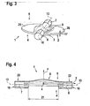
- FIG. 3 is the side view of a slightly tilted throttle according to the present invention can be seen.
- FIG. 3 shows that on both sides of the groove 9 on the downstream side of its first surface area 25 and a second surface area 26 extend.
- the first surface region 25 and the second surface region 26 are in communication with one another via the material of the flap surface deformed by the groove 9, wherein the material thickness 17 in the region of the first surface region 25, within the second surface region 26 and in the region of the formation 8 or 9 in FIG Is essentially the same.
- the substantially planar formed first and second surface regions 25, 26 merge into one another in the region of the groove 9, ie in the region of the formation on the flap surface 2 of the throttle flap 1, and form a stiffening with regard to the flexural strength of the throttle flap element 1 proposed according to the invention.
- the formation 8 or 9 between the first surface region 25 and the second surface region 26 makes it possible to dispense with a continuous throttle shaft since the stiffening with respect to the true bending moment of the first surface region 25 and the second surface region 26 of the flap surface 2 by the formation. 8 , 9 is applied and thus makes the formation of a continuous throttle shaft obsolete.
- the throttle valve 1 is preferably manufactured as an injection molding component in one operation within a molding tool.
- the flow of plastic melt within the closed mold can be assisted by flow aids.
- one or more rib-shaped flow aids can be mounted in the convex design 8 in the area 2. These are located inside the Ausformungs Kunststoffes in the flap surface 2.
- corresponding negative molds can be provided on the injection molds. The flow aids are not visible from the inflow side 4 of the surface area 2.
- FIG. 4 produced with a coordinate system shown throttle valve 1 in one operation.
- FIG. 4 is a distance 21, in which the facing end faces of the first pin 6 and the second pin 7 are opposite. Within the distance 21, the required with regard to the bending moments due to the flow of the throttle flap surface 1 strength of the throttle valve is applied exclusively by the formation in the flap surface 2, without the need for a ribbing on the inflow side 4 and the downstream side 5 of the flap surface 2.
- the peripheral surfaces of the first pin 6 and the second pin 7, in which the inventively proposed throttle wall of an intake air or charge air duct is received, is designated by reference numeral 22, while the outer side end faces of the first pin 6 and the second pin. 7 indicated by the reference numeral 16 are.
- Perpendicular to the drawing plane according to FIG. 4 extends the X-axis of in FIG. 4 shown coordinate system in the spatial directions x, y and z.
- FIG. 5 shows the top view of the throttle valve according to FIG. 1 .
- the Z-axis of the coordinate system in the spatial directions X, Y and Z extends perpendicular to the plane of the drawing, while the course of the Y-axis coincides with the line of symmetry 13 of the throttle valve 1.
- the X-axis extends in the radial direction with respect to the flap surface 2 of the throttle valve 1.
- the injection point for the formed in the area 2 in a convex shape 8 coincides with the origin of the Z-axis of the coordinate system. From this injection point, the plastic melt flows within the mold, supported by the flow aids formed in the molding tool in the radial direction and forms the surface region 2 with a curved shaped molding 8 in consistently uniform material thickness.
- the representation according to FIG. 5 can be taken that the curvature curve 28 is parallel to the axis of symmetry 13 of the throttle valve 1, wherein the axis of symmetry 13 of the throttle valve 1 as shown in FIG FIG. 5 coincides with the pivot axis of the throttle surface 2.
- the sublime from the drawing level according to FIG. 5 The protruding formation 8 is characterized by a uniform course with respect to the axial extension of the axis of symmetry 13, the formation 8 assuming its maximum in the region of the Z-axis protruding from the plane of the drawing according to FIG. 5 with respect to the line of symmetry 13 of the throttle flap 1 (see FIG Representation according to FIG. 4 ).
- the representation according to FIG. 6 is the intersection VI - VI according to FIG. 5 refer to.
- the Z-axis of the coordinate system in the three spatial directions x, y, z is perpendicular, while the X-axis extends into the horizontal.
- the in FIG. 6 illustrated sectioning through the flap surface 2 of the throttle valve 1 according to FIG. 5 passes through the second transition region 11 as shown in FIG FIG. 5 .
- From the illustration according to FIG. 6 shows that the material thickness 17 viewed in the direction of the X-axis, in the first area 25 and in the region of the formation 8, 9 and within the second area 24 of the throttle valve 1 is substantially constant.
- the limited by the end face of the second pin 7 groove 9 is according to the section line VI-VI in FIG.
- the radius of curvature 15 of the groove 9 on the downstream side of the throttle damper 1 is greater than the first radius of curvature 14 in the region of the groove 9 delimited by the end face of the second stud.
- the course of the radius of curvature is the same as that shown in FIG FIG. 5 from the Z-axis assigning end face of the second pin 7 continuously to the cutting plane 7 as shown in FIG. 5 to decrease continuously from there along the Y-axis in the direction of the z-axis assigning end face of the first pin 6.
- the curvature profile 28 takes in the region of the sectional plane characterized by a semicircular curvature in the plate surface of Drosselelldappe 1, which is defined in the sectional plane VI-VI by the further radius of curvature 15, which in the illustration according to FIG. 6 was selected as an example.
- FIG. 7 has the-Schnittverlauf VII-VII according to the plan view of the throttle valve in FIG. 5 ,
- section profile VII-VII shows that the radius of curvature of the groove 9 in the Z-axis assumes its maximum value.
- the maximum radius of curvature 27 in the illustration according to FIG. 7 For example, the throttle valve 1 on the inflow side 4, the largest deformation, ie the curvature curve 28 of the flap surface of the throttle valve 1 assumes its maximum here.
- Due to the in FIG. 5 illustrated transition regions on both sides of the position of the maximum radius of curvature 27 is achieved by the formation 8, 9 in the flap surface of the throttle valve 1 an immense flexural rigidity improvement of the throttle valve 1.
- One the flap surface of the Throttle valve 1 stiffening, continuously extending throttle shaft can now be omitted, so that in FIG. 5 shown first pin 6 and second pin 7 sufficient as storage locations for the inventively shaped throttle valve 1.
- the second transition region 11 within which the radius of curvature steadily increases from a value corresponding to the first radius of curvature 14 to a value corresponding to the maximum radius of curvature 27, seen continuously within the first transitional range 10 in the Y direction, again from the maximum radius of curvature 27 on the first radius of curvature 14 at the z-axis zu josde Stirnseite- the first pin 6 fall.
- the selected contour of the shape in the flap surface of the throttle valve 1 a substantially parallel to the axis of symmetry 13 of the throttle valve 1 extending stiffening structure is created.
- the stiffening effect of the shape 8, 9 in the flap surface of the throttle valve 1 makes reinforcing ribs on the inflow side 4 and the outflow side 5 of the throttle valve 1 unnecessary.
- the material thickness 17 within the first surface area 25, which is formed essentially planar and the shape 8, 9 in the flap surface of the throttle valve 1 and within the second area 26 substantially constant, so that accumulations of material both in the flap surface in all three spatial directions x , y, - z are minimized.
- the flap surface 2 of the throttle valve 1, which is preferably manufactured as Spritzg tellbauteil, is bounded by a border 3, which conforms to the not shown wall of Ansaug poverty- or Aufladeluftkanals an internal combustion engine depending on the pivot position of the throttle about its axis of symmetry 13.
- the flexural strength of the inventively proposed throttle for use in the intake / charge air duct of an internal combustion engine, not shown here can be influenced by the shape of the formation 8 and 9 and by the shape of the curvature curve 28 parallel to the axis of symmetry 13 of the throttle valve 1.
- the transition regions 10 and 11, on both sides of the Z-axis as shown in FIG. 5 For example, they can also be larger than those in FIG. 6 respectively.
- FIG. 7 formed radii of curvature are formed.
- a bending stiffness improvement of the throttle valve element 1 proposed according to the invention can also be achieved by selecting the plastic material to be injected into the molding tool.
- a uniform flow of the plastic material injected as a plastic melt into the molding tool can be achieved by flow aids arranged in the region of the molding, which can be designed in the form of rib-shaped channels.
- the flow aids are located on the side facing away from the inflow 4 side of the surface area 2 of the throttle valve. 1
- the transition regions 10 and 11 contains both sides of the Z-axis
- the convex curved in the flap surface 2 of the throttle valve 1 executed Ausformung 8 also without transition regions 10 and 11 respectively be.
- the convexly curved shape 8 extends in the flap surface 2 of the throttle valve 1 over the entire flap surface 2, without flat surface areas are formed in the flap surface 2 except a flat ring on the edge of the flap surface 2.
Landscapes
- Engineering & Computer Science (AREA)
- General Engineering & Computer Science (AREA)
- Mechanical Engineering (AREA)
- Chemical & Material Sciences (AREA)
- Combustion & Propulsion (AREA)
- Lift Valve (AREA)
- Control Of Throttle Valves Provided In The Intake System Or In The Exhaust System (AREA)
Description
- Bei Verbrennungskraftmaschinen kommen im Saugrohrtrakt Drosselverstellvorrichtungen zum Einsatz, mit denen das von der Verbrennungskraftmaschine benötigte Luftvolumen zur Verbrennung des Kraftstoffes reguliert werden kann. Die Drosselverstellvorrichtung umfasst in der Regel einen Antrieb, die an einer Welle aufgenommene Drosselklappe sowie ein zweiteiliges Drosselgehäuse, welches aus Metallguss gefertigt oder als Kunststoffspritzteil ausgebildet sein kann. Am Drosselgehäuse wird zudem vielfach ein separater Gehäusedeckel vorgesehen, mit welchem das Gehäuse zum Schutz gegen Ansaugen von Fremdluft abgedichtet werden kann. Zur Versteifung umfassen die eingesetzten Drosselklappen in der Regel eine angespritzte Verrippung.
-
DE 43 29 522 A1 hat eine Drosseleinrichtung zum Gegenstand, welche im Ansaugkanal einer Brennkraftmaschine eingebaut wird. Die Drosseleinrichtung besteht aus einem Gehäuse, einer Drosselklappenansteuerung, einem Positionsdetektor, einer an einer Drossenklappenwelle befestigten Drosselklappe, wobei die Drosseleinrichtung zwischen dem reinluftseitigen Luftfilteranschluss und der Sauganlage der Brennkraftmaschine angeordnet ist. Der Luftfilteranschluss und/oder die Sauganlage bestehen aus einem Kunststoff wobei die einzelnen Elemente der Drosseleinrichtung modular aufgebaut sind und über Steck-, Schraub- oder Spannverbilldungen miteinander fügbar sind. Gehäuse und/oder die Drosselklappe können aus Kunststoff bestehen. Die Drosselklappenwelle ist zweiteilig aufgebaut. Auf einer Wellenhälfte der Drosselklappenwelle kann das Modul für den Lagesensor und auf der anderen Wellenhälfte das Modul für die Drosselklappenverstelleinheit angeordnet werden. Stelleinheit, Stellsensor, Drosselklappe und Drosselklappenwelle bilden eine gemeinsame Einheit.
WO 59 2493 A1 WO 59 2493 A1 DE 100 55 397 . -
DE 195 25 510 A1 hat eine Drosselklappenstelleinheit zum Gegenstand. Die Drosselklappenstelleinheit umfasst eine an einer in einem Drosselklappenstutzen drehbar gelagerten Drosselldappenwelle befestigte Drosselklappe. Ferner ist ein mit der Drosselklappenwelle gekoppelter, am Drossenklappenstutzen gelagerte Stellmotor zum Verstellen der Drosselklappenwelle vorgesehen. Dieser umfasst mindestens einen Schleifer und mindestens eine Potentiometerbahn zum Erfassen einer Stellposition der Drosselklappenwelle sowie einen elekctrischen Anschluss. An diesem ist innerhalb eines Anschlussraumes der Stellmotor und ein Potentiometer angeschlossen. Ferner ist ein den Anschlussraum abschließendes Dekkelelement vorgesehen. Die mindestens eine Potentionmeterbahn ist am Deckel angebracht, wobei am Deckel ein zum elektrischen Anschluss gehörendes Kupplungsteil angeformt wird. -
DE 199 14 994 A1 hat einen spritzgegossenen Drosselkörper zum Gegenstand. Die Drosselplatte mit Welle und einer Hebeleinheitsbaugruppe beinhaltet ein zentrales Plattenteil, Lagerteile sowie ein Drosselkabelverbindungsteil und ein Ende eines Positionssensors. Das Plattenbauchteil ist in seinem zentralen Teil verstärkt ausgebildet und verjüngt sich nach aussen hin zu den Randteilen. Eine Anzahl von verstärkenden Rippen wird auf der oberen und unteren Oberfläche des Plattenteiles angeformt. Das Profil dieser Rippen sorgt für einen verbesserten Luftstrom über der Oberfläche der Platte zur Erhöhung zur Verbesserung der Strömungsführung, Die Rippen dienen andererseits der Verstärkung bzw. Versteifung der Drosselplatte. - Mit der erfindungsgemäß vorgeschlagen Lösung wird eine Drosselklappe, die hinsichtlich ihrer Biegefestigkeit optimiert ist, bereitgestellt. Die erfindungsgemäß vorgeschlagene Drosselklappe lässt sich als Spritzgießbauteil besonders einfach herstellen, da keine das Verfließen des Kunststoffmateriales innerhalb der Form behindernden Verrippungen erforderlich sind. Die Kunststoffschmelze kann ungehindert innerhalb des Hohlraumes der Form verfließen. Durch die Gestaltung des im Spritzgießverfahren gefertigten Drosselklappe wird eine hinsichtlich ihrer Biegefestigkeit optimierte Drosselklappe erhalten. Anstelle von Verstärkungsrippen wird an der Drosselklappe eine gezielte Ausformung erzeugt, die an der Anströmseite der Drosselklappe im Ansaug-/Aufladetrakt der Verbrennungskraftmaschine eine Ausbauchung aufweist und an der Abströmseite durch eine Hohlkehle gekennzeichnet ist. Dadurch wird an der Drosselklappe parallel zur Symmetrieachse, die mit der Schwenkachse der Drosselklappe zusammenfällt, eine Versteifung erzielt, die eine Rippenstruktur an der Oberseite bzw. der Unterseite der Klappenflächen überflüssig macht.
- Die im Querschnitt der Drosselklappe gesehen als Wölbung in der Klappenfläche ausbildbare Ausformung der Drosselklappe umfasst Übergangsbereiche, die sich in radiale Richtung der Klappenfläche erstrecken. Diese Übergangsbereiche sind durch kontinuierlich zunehmende bzw. kontinuierlich abnehmende Krümmungsradien gekennzeichnet. Dadurch entsteht in der Klappenfläche eine gleichmäßige, die Strömung begünstigende Ausformung, in deren Mitte der maximale Krümmungsradius zwischen den beide erwähnten Übergangsbereichen liegt.
- In fertigungstechnisch besonders vorteilhafte Beweise lassen sich an der Drosselklappe zwei Zapfen in einem Fertigungsvorgang anspritzen. Diese an zwei Anschlußstellen an der Klappenfläche angespritzten Zapfen bilden Lagerungsstelle für die Drosselklappe in der Wandung eines Strömungskanales wie z. B eines Ansaugluftkanales im Ansaugtrakt bzw. zwischen einem Ladeluftkanal im Ladelufttrakt einer Verbremiungskraftmaschine. Die Zapfen liegen koaxial zur Symmetrieachse der Drosselklappe, so dass auf eine durchgehende Drosselklappenwelle verzichtet werden kann; die Versteifung der Klappenfläche in der Mitte des Strömungskanals wird dort durch eine Ausformung der Klappenfläche erreicht. Eine durchgängige Drosselklappenwelle kann mit der erfindungsgemäßen Lösung umgangen werden. Um eine gleichmäßige Stärke der Drosselldappenfläche zu erreichen, können in den Formenhälften der Spritzgießformen für die Drosselklappen als Vertiefungen ausgebildete Fließhilfen angeordnet sein, mit deren Hilfe ein gleichmäßigeres Verfließen der Kunststoffschmelze vom Anspritzpunkt bis zu den von diesen auch weit entfernten Endbereichen am Umfang der Klappenfläche herbeigeführt werden kann.
- Anhand der Zeichnung wird die Erfindung nachfolgend eingehender-beschrieben.
- Es zeigt:
-
Figur 1 die perspektivische Draufsicht auf eine erfindungsgemäß geformte Drosselklappe, -
Figur 2 eine perspektivische Unteransicht auf eine erfindungsgemäß geformte Drosselklappe mit Hohlkehle, -
Figur 3 eine Seitenansicht einer leicht gekippten Drosselklappe gemäß der vorliegenden Erfindung, -
Figur 4 die Seitenansicht der erfindungsgemäßen Drosselklappe, -
Figur 5 die Draufsicht auf die Drosselklappe gemäßFigur 1 , -
Figur 6 den Schnittverlauf VI - VI gemäßFigur 5 und -
Figur 7 den Schnittverlauf VII - VII gemäßFigur 5 . - Der Darstellung gemäß
Figur 1 ist die perspektivisch wiedergegebene Draufsicht auf eine erfindungsgemäß geformte Drosselklappe zu entnehmen. - In
Figur 1 ist eine Drosselklappe 1 dargestellt, an deren Klappenfläche 2 jeweils ein erster Zapfen 6 und zweiter Zapfen 7 angespritzt sind. In der Klappenfläche 2 der Drosselklappe 1 ist eine Ausformung 8 ausgebildet. Die Ausformung 8 kann sich koaxial oder auch versetzt in Bezug auf den ersten Zapfen 6 und den zweiten Zapfen 7 verlaufend in der Klappenfläche 2 der Drosselklappe 1 erstrecken. In Bezug auf eine Anströmseite 4 der Drosselklappe 1 imFigur 1 nicht dargestellten Ansaug-/Aufladetrakt einer Verbrennungslcraftmaschine, ist die Ausformung 8 als Wölbung oder Ausbauchung ausgebildet, die auf einer Abströmseite 5, d. h. der Unterseite der Drosselklappe 1 gemäß der darstellendenFigur 1 inFigur 1 nicht dargestellte Hohlkehle aufweist (vergleicheFigur 2 ). Die inFigur 1 dargestellte Drosselklappe 1 kann sowohl stromaufwärts vor einer Brennkraftmaschine, d.h. auf deren ansaugseitiger Seite eingesetzt werden als auch stromabwärts hinter der Brennkraftmaschine, d.h. im Abgastrakt oder auch im Rahmen einer Luft- bzw. Abgasrückführung in den Ansaug-/Anfladetrakt einer Brennkraftmaschine. - Die sich beiderseits der Ausformung 8 erstreckenden Bereiche der Klappenfläche 2 sind durch eine Umrandung 3 begrenzt, welche sich je nach Anstellung der Drosselklappe 1 innerhalb eines Ansaugluftkanals im Ansaugtrakt bzw. innerhalb eines Ladeluftkanals im Aufladetrakt einer Verbrennungskraftmaschine an die Wandung eines die Drosselklappe 1 umgebenden Strömungskanals einstellt und dementsprechend eine Luftspalt freigibt oder verschließt, über den die Verbrennungsluft bzw. die Ladeluft der Verbrennungskraftmaschine zugeführt wird. Der Vollständigkeit halber sei erwähnt, dass der erste Zapfen 6 bzw. der zweite Zapfen 7 eine Stirnseite 16 umfasst. Am ersten Zapfen 6 kann ein Drehwinkelgeber für die Drosselklappe 1 aufgenommen sein, während über den zweiten Zapfen 7 die Schwenkbewegung in die Drosselklappe 1 eingeleitet wird, so beispielsweise über einen pneumatisch oder elektrisch antreibbaren Stellantrieb, der in
Figur 1 jedoch nicht dargestellt ist. Der Drehwinkelgeber und der Stellantrieb können auch gemeinsamen am ersten Zapfen 6 sowie gemeinsam am zweiten Zapfen 7 der Drosselklappe 1 angeordnet werden. -
Figur 2 ist eine perspektivische Unteransicht auf eine erfindungsgemäß geformte Drosselklappendarstellung der Hohlkehle zu entnehmen. - Aus der Darstellung gemäß
Figur 2 geht hervor, dass der erste Zapfen 6 bzw. der zweite Zapfen 7 an einer ersten Anschlußstelle 23 bzw. an einer zweiten Anschlußstelle 24 im äußeren Randbereich der Drosselldappenfläche 2 angespritzt sind. Der erste Zapfen 6 bzw. der zweite Zapfen 7 liegen in Bezug auf eine Symmetrieachse 13, die mit der Schwenkachsen der Drosselklappen 1 zusammenfällt, beabstandet voneinander und bilden die Lagerungstellen, in denen die Drosselklappe 1 in der Wandung eines Ladeluftkanals bzw. eines Ansaugluftkanals einer Verbrennungskraftmaschine schwenkbar aufgenommen ist. Der erste Zapfen 6 und der zweite Zapfen 7 liegen in Bezug auf die Symmetrieachse 13 der Drosselklappe 1 fluchtend zueinander. Während ausFigur 1 die konvex gekrümmte Ausbauchung zwischen dem ersten Zapfen 6 und dem zweiten Zapfen 7 an der Anströmseite 4 der Drosselldappe 1 dargestellt ist, lässt sichFigur 2 die auf der Abströmseite 5 der Drosselklappe 1 liegende Hohlkehle 9, die durch die einander zuweisenden Stirnseiten des ersten Zapfens 6 bzw. des zweiten Zapfens 7 begrenzt ist, entnehmen. Die Hohlkehle 9 bildet die Rückseite der Ausformung 8 gemäß der Darstellung inFigur 1 . Die Hohlkehle 9 erstreckt sich im Wesentlichen parallel zur Symmetrieachse 13 der Drosselklappe 1, die gleichzeitig deren Schwenkachse und den ersten Zapfen 6 bzw. den zweiten Zapfen 7 bildet. Die Klappenfläche 2 der Drosselklappe 1 ist durch die Umrandung 3 begrenzt, die sich in Schließstellung der Drosselklappe 1 im Ansaug- bzw. im Ladeluftkanal einer Verbrennungskraftmaschine an die Wandung des jeweiligen Kanals anliegt und diesen verschliesst; in einer um 90° zu Fließstellung orientierten Position der Drosselklappe 1 im Ansaug- bzw. im Ladeluftkanal der Verbrennungskraftmaschine gibt die Drosselklappe fast den gesamten Strömungsquerschnitts des Ansaugluft- bzw. Ladeluftkanales der Verbrennungskraftmaschine frei. -
Figur 3 ist die Seitenansicht einer leicht gekippten Drosselklappe gemäß der vorliegenden Erfindung zu entnehmen. - Aus
Figur 3 geht hervor, dass sich beidseits zur Hohlkehle 9 auf der Abströmseite Sein erster Flächenbereich 25 sowie ein zweiter Flächenbereich 26 erstrecken. Der erste Flächenbereich 25 sowie der zweite Flächenbereich 26 stehen über das durch die Hohlkehle 9 verformte Material der Klappenfläche in Verbindung miteinander, wobei die Materialstärke 17 im Bereich des ersten Flächenbereiches 25, innerhalb des zweiten Flächenbereiches 26 sowie im Bereich der Ausformung 8 bzw. 9 im Wesentlichen gleich ist. Die im Wesentlichen plan ausgebildeten ersten und zweiten Flächenbereiche 25, 26 gehen im Bereich der Hohlkehle 9, d. h. im Bereich der Ausformung an der Klappenfläche 2 der Drosselklappe 1, ineinander über und bilden eine hinsichtlich der Biegefestigkeit des erfindungsgemäß vorgeschlagenen Drosselklappenelements 1 wirkende Versteifung. Die Ausformung 8 bzw. 9 zwischen dem ersten Flächenbereich 25 und dem zweiten Flächenbereich 26 erlaubt den Verzicht auf eine durchgängige Drosselklappenwelle, da die Versteifung hinsichtlich des auf dem wahren Biegemomentes des ersten Flächenbereiches 25 bzw. des zweiten Flächenbereiches 26 der Klappenfläche 2 durch die Ausformung 8, 9 aufgebracht wird und demnach die Ausbildung einer durchgängigen Drosselklappenwelle obsolet macht. - Aus der Darstellung gemäß
Figur 4 ist die Seitenansicht der erfindungsgemäßen Drosselklappe zu entnehmen. Die Drosselklappe 1 wird bevorzugt als ein Spritzgießbauteil in einem Arbeitsgang innerhalb eines Formwerkzeuges gefertigt. Das Verfließen der Kunststoffschmelze innerhalb des geschlossenen Formwerkzeuges kann durch Fließhilfen unterstützt werden. Um ein Verfließen der fließfähigen Kunststoffschmelze innerhalb der geschlossenen Formenteile einer Spritzgießform zu gewährleisten, insbesondere ein Verfließen der Kunststoffschmelze in die Randbereiche der Klappenfläche 2 der Drosselklappe 1, können in der konvex ausgebildeten Ausformung 8 im Flächenbereich 2 eine oder mehrere rippenförmig ausgebildete Fließhilfen angebracht werden. Diese befinden sich innerhalb des Ausformungsbereiches in der Klappenfläche 2. Dazu können an den Spritzgießformen entsprechende Negativformen vorgesehen werden. Die Fließhilfen sind von der Anströmseite 4 des Flächenbereiches 2 aus nicht sichtbar. Diese durch das Vorsehen von Fließhilfen im Formwerkzeug ausgebildeten Rippen bieten eine zusätzliche Versteifung des Flächenbereiches 2, jedoch sind diese Verrippungen am Flächenbereich 2 nicht so stark ausgebildet, da die Versteifung hinsichtlich des Biegemomentes des Flächenbereiches 2 durch die konvex ausgebildete Ausformung 8 erheblich erhöht wird. - Innerhalb des geschlossenen Formwerkzeuges kann die in
Figur 4 mit einem Koordinatensystem dargestellte Drosselklappe 1 in einem Arbeitsgang gefertigt werden. In einem Arbeitsgang lässt sich sowohl die Ausformung 8 bzw. 9 in der Klappenfläche 2 der Drosselklappe 1, erzeugen als auch der erste Zapfen 6 bzw. der zweite Zapfen 7 im Randbereich Drosselklappenfläche 2 an Anschlußstellen (vergleiche Darstellung gemäßFigur 2 ) anspritzen. - Aus der Darstellung gemäß
Figur 4 geht hervor, dass die auf der Anströmseite 4 der Drosselklappe liegende Ausbauchung 8 oder Auswölbung einen Verlauf 28 aufweist. Der Wölbungs- bzw. Verformungsverlauf 28, der Ausformung 8 bzw. 9 an der Klappenfläche 2 findet ihr Maximum etwa in der Mitte der Drosselklappenfläche sich in Richtung Z-Achse erstreckend. Der Wölbungs- bzw. Verformungsverlauf 28 der Drosselklappe auf der Anströmseite 4 ist durch stetige Übergänge, die sich in Y-Richtung auf der Anströmseite 4 der Drosselklappenfläche erstrecken, gekennzeichnet. Die die Biegefestigkeit der erfindungsgemäß vorgeschlagenen Drosselklappe 1 beträchtlich erhöhende Ausformung verläuft parallel zur Symmetrieachse 13 der Drosselklappe 1, die ihrerseits mit der Schwenkachse der Drosselklappe zusammenfällt. Die auf der Abströmseite 5 liegende Hohlkehle 9, welche die Ausbauchung oder Wölbung 8 begrenzt, ist inFigur 4 nicht dargestellt. AusFigur 4 geht ein Abstand 21 hervor, in welchem sich die einander zuweisenden Stirnseiten des ersten Zapfens 6 und des zweiten Zapfens 7 gegenüberliegen. Innerhalb des Abstandes 21 wird die hinsichtlich der auftretenden Biegemomente aufgrund der Anströmung der Drosselklappenfläche 1 erforderliche Festigkeit der Drosselklappe ausschließlich durch die Ausformung in der Klappenfläche 2 aufgebracht, ohne dass es einer Verrippung auf der Anströmseite 4 bzw. der Abströmseite 5 der Klappenfläche 2 bedarf. Die Umfangsflächen des ersten Zapfens 6 bzw. des zweiten Zapfens 7, in denen die erfindungsgemäß vorgeschlagene Drosselklappe der Wandung eines Ansaugluft- bzw. Ladeluftkanales aufgenommen wird, ist mit Bezugszeichen 22 bezeichnet, während die aussenseitigen Stirnseiten des ersten Zapfens 6 bzw. des zweiten Zapfens 7 durch das Bezugszeichen 16 gekennzeichnet sind. Senkrecht zur Zeichenebene gemäßFigur 4 erstreckt sich die X-Achse des inFigur 4 dargestellten Koordinatensystems in die Raumrichtungen x, y und z. -
Figur 5 zeigt die Draufsicht auf die Drosselklappe gemäßFigur 1 . - Die Z-Achse des Koordinatensystems in die Raumrichtungen X, Y und Z erstreckt sich senkrecht zur Zeichenebene, während der Verlauf der Y-Achse mit der Symmetrielinie 13 der Drosselklappe 1 zusammenfällt. Senkrecht zur Y-Achse erstreckt sich die X-Achse in radialer Richtung in Bezug auf die Klappenfläche 2 der Drosselklappe 1. Die Anspritzstelle für die im Flächenbereich 2 in konvexer Form ausgebildete Ausformung 8 fällt mit dem Ursprung der Z-Achse des Koordinatensystems zusammen. Von dieser Anspritzstelle aus verfließt die Kunststoffschmelze innerhalb des Formenwerkzeuges, unterstützt durch die im Formenwerkzeug ausgebildeten Fließhilfen in radiale Richtung und bildet den Flächenbereich 2 mit einer gewölbt geformten Ausformung 8 in durchgängig gleichmäßige Materialstärke.
- Koaxial zu Symmetrielinie 13 der Drosselklappe 1 erstrecken sich der erste Zapfen 6 bzw. der zweite Zapfen 7, deren Stirnseiten jeweils mit Bezugszeichen 16 und deren Umfangsflächen mit Bezugszeichen 22 identifiziert sind. In die Zeichenebene gemäß
Figur 5 ist ein Schnitt durch die Klappenfläche 2 der Drosselldappe 1 geklappt. Aus der Schnittdarstellung geht hervor, dass der Krümmungsradius der Ausformung 8 in Richtung des Mittelpunlctes der Klappenfläche 2, der mit der Z-Achse gemäßFigur 5 zusammenfällt stetig zunimmt, während der Krümmungsradius der Ausformung 8 der Klappenfläche 2 innerhalb des zweiten Übergangsbereiches 11 von der Z-Achse auf dem zweiten Zapfen 7, kontinuierlich abnimmt. Der maximale Krümmungsradius im Wölbungsverlauf 28 der Ausformung 8 fällt mit der aus der Zeichenebene herausragende Z-Achse zusammen (Vergleiche Darstellung gemäßFigur 7 ). - Der Darstellung gemäß
Figur 5 ist entnehmbar, dass der Wölbungsverlauf 28 parallel zur Symmetrieachse 13 der Drosselklappe 1 liegt, wobei die Symmetrieachse 13 der Drosselklappe 1 gemäß der Darstellung inFigur 5 mit der Schwenkachse der Drosselklappenfläche 2 zusammenfällt. Die erhaben aus der Zeichenebene gemäßFigur 5 vorstehende Ausformung 8 ist in Bezug auf die axiale Streckung der Symmetrieachse 13 durch einen gleichmäßigen Verlauf gekennzeichnet, wobei die Ausformung 8 in Bezug auf die Symmetrielinie 13 der Drosselldappe 1 ihr Maximum im Bereich der aus der Zeichenebene gemäß Figur 5 herausragenden Z-Achse annimmt (vergleiche Darstellung gemäßFigur 4 ). - Der Darstellung gemäß
Figur 6 ist der Schnittverlauf VI - VI gemäßFigur 5 zu entnehmen. Die Z-Achse des Koordinatensystems in die drei Raumrichtungen x, y, z verläuft senkrecht, während die X-Achse in die Horizontale reicht. Der inFigur 6 dargestellt Schnittverlauf durch die Klappenfläche 2 der Drosselklappe 1 gemäßFigur 5 verläuft durch den zweiten Übergangsbereich 11 gemäß der Darstellung inFigur 5 . Aus der Darstellung gemäßFigur 6 geht hervor, dass die Materialstärke 17 in Richtung der X-Achse betrachtet, im ersten Flächenbereich 25 sowie im Bereich der Ausformung 8, 9 und innerhalb des zweiten Flächenbereiches 24 der Drosselklappe 1 im Wesentlichen konstant ist. Die durch die Stirnseite des zweiten Zapfens 7 begrenzte Hohlkehle 9 ist gemäß des Schnittverlaufes VI-VI inFigur 5 durch einen ersten Krümmungsradius 14 sowie durch einen weiteren Krümmungsradius 15 geprägt, der in der Schnittebene VI-VI liegt. Innerhalb der Schnittebene VI-VI ist der Krümmungsradius 15 der Hohlkehle 9 an der Abströmseite der Drosselldappe 1 größer als der erste Krümmungsradius 14 im Bereich der durch die Stirnseite des zweiten Zapfens begrenzte Hohlkehle 9. Der Verlauf des Krümmungsradius nimmt gleich der Darstellung gemäßFigur 5 von der der Z-Achse zuweisenden Stirnseite des zweiten Zapfens 7 kontinuierlich bis zur Schnittebene 7 gemäß der Darstellung inFigur 5 zu, um von dort kontinuierlich entlang der Y-Achse in Richtung auf die der Z-Achse zuweisende Stirnseite des ersten Zapfens 6 abzunehmen. Auf der Anströmseite 4 der Drosselklappe 1 gemäß der Darstellung inFigur 6 ist der Wölbungsverlauf durch das Bezugszeichen 28 gekennzeichnet. Der Wölbungsverlauf 28 nimmt im Bereich der Schnittebene durch eine halbkreisförmige Krümmung in der Plattenfläche der Drosselldappe 1 gekennzeichnet, die in der Schnittebene VI-VI durch den weiteren Krümmungsradius 15 definiert ist, welche in der Darstellung gemäßFigur 6 exemplarisch herausgegriffen wurde. -
Figur 7 hat den-Schnittverlauf VII-VII gemäß der Draufsicht auf die Drosselklappe inFigur 5 . - Aus dem in
Figur 7 dargestellten Schnittverlauf VII-VII geht hervor, dass der Krümmungsradius der Hohlkehle 9 im Bereich der Z-Achse seinen maximalen Wert annimmt. Im Vergleich zum ersten Radius 14, welcher an der Stirnseite des zweiten Zapfens 7 liegt, beträgt der maximale Krümmungsradius 27 in der Darstellung gemäßFigur 7 beispielsweise das Doppelte des ersten Krümmungsradius 14. Demgemäß weist die Drosselklappe 1 auf der Anströmseite 4 die größte Verformung auf, d. h. der Wölbungsverlauf 28 der Klappenfläche der Drosselklappe 1 nimmt hier sein Maximum an. Aufgrund der inFigur 5 dargestellten Übergangsbereiche beiderseits der Position des maximalen Krümmungsradius 27 wird durch die Ausformung 8, 9 in der Klappenfläche der Drosselklappe 1 eine immense Biegesteifigkeitverbesserung der Drosselklappe 1 erreicht. Eine die Klappenfläche der Drosselklappe 1 versteifende, durchgängig verlaufende Drosselklappenwelle kann nunmehr entfallen, so dass die inFigur 5 dargestellten ersten Zapfen 6 bzw. zweiten Zapfen 7 als Lagerungsstellen für die erfindungsgemäß ausgeformte Drosselklappe 1 ausreichen. - Zwischen dem ersten Krümmungsradius 14 und dem maximalen Krümmungsradius 27 gemäß der Darstellung in
Figur 7 verläuft der zweite Übergangsbereich 11, innerhalb dessen der Krümmungradius stetig von einem-dem ersten Krümmungsradius 14 entsprechenden Wert auf einen dem maximalen Krümmungsradius 27 entsprechenden Wert ansteigt, um innerhalb des ersten Übergangsbereiches 10 in Y-Richtung gesehen, kontinuierlich vom maximalen Krümmungsradius 27 wieder auf den ersten Krümmungsradius 14 an der der Z-Achse zuweisende Stirnseite- des ersten Zapfens 6 abzufallen. Durch die gewählte Kontur der Ausformung in der Klappenfläche der Drosselklappe 1 wird eine sich im Wesentlichen parallel zur Symmetrieachse 13 der Drosselklappe 1 erstreckende versteifende Struktur geschaffen. Die versteifende Wirkung der Ausformung 8, 9 in der Klappenfläche der Drosselklappe 1 macht Verstärkungsrippen auf der Anströmseite 4 bzw. der Abströmseite 5 der Drosselklappe 1 entbehrlich. Die Materialstärke 17 innerhalb des ersten Flächenbereiches 25, der im Wesentlichen plan verlaufend ausgebildet ist sowie der Ausformung 8, 9 in der Klappenfläche der Drosselklappe 1 und innerhalb des zweiten Flächenbereiches 26 im Wesentlichen konstant, so dass Materialanhäufungen sowohl in der Klappenfläche in alle drei Raumrichtungen x, y,- z minimiert werden. Die Klappenfläche 2 der Drosselklappe 1, die bevorzugt als Spritzgießbauteil gefertigt wird, ist von einer Umrandung 3 begrenzt, welche sich an die nicht dargestellte Wandung eines Ansaugluft- bzw. Aufladeluftkanals einer Verbrennungskraftmaschine je nach Schwenkposition der Drosselklappe um ihre Symmetrieachse 13, anschmiegt. Die Biegefestigkeit der erfindungsgemäß vorgeschlagenen Drosselklappe zum-Einsatz im Ansaug-/Ladelufttrakt einer hier nicht dargestellten Verbrennungskraftmaschine läßt sich durch die Formgebung der Ausformung 8 bzw. 9 sowie durch die Formgebung hinsichtlich des Wölbungsverlaufes 28 parallel zur Symmetrieachse 13 der Drosselklappe 1 beeinflussen. Die Übergangsbereiche 10 bzw. 11, beidseits der Z-Achse gemäß der Darstellung inFigur 5 können beispielsweise auch in größeren, als den inFigur 6 bzw.Figur 7 dargestellten Krümmungsradien ausgebildet werden. Eine Biegesteifigkeitsverbesserung des erfindungsgemäß vorgeschlagenen Drosselklappenelementes 1 kann auch durch die Auswahl des in das Formwerkzeug einzuspritzenden Kunststoffmaterials erfolgen. Ein gleichmäßiges Verfließen des als Kunststoffschmelze in das Formwerkzeug eingespritzten Kunststoffmaterials läßt sich durch im Bereich der Ausformung angeordnete Fließhilfen, die in Gestalt rippenförmiger Kanäle ausgebildet sein können, erreichen. Die Fließhilfen liegen auf der der Anströmseite 4 abgewandten Seite des Flächenbereiches 2 der Drosselklappe 1. - Während in den
Figuren 5, 6 und 7 eine Formgebung der Ausformung 8 im Flächenbereich 2 der Drosselklappe 1 dargestellt ist, die Übergangsbereiche 10 bzw. 11 beidseits der Z-Achse enthält, kann die in der Klappenfläche 2 der Drosselklappe 1 konvex gewölbt ausgeführt Ausformung 8 auch-ohne Übergangsbereiche 10 bzw. 11 ausgebildet sein. In dieser Ausführungsvariante erstreckt sich die konvex gewölbte Ausformung 8 in der Klappenfläche 2 der Drosselklappe 1 über die gesamte Klappenfläche 2, ohne daß außer einem planen Ring am Rand der Klappenfläche 2 flache Flächenbereiche in der Klappenfläche 2 ausgebildet sind. -
- 1 -
- Drosselklappe
- 2
- Klappenfläche
- 3
- Umrandung
- 4
- Anströmseite
- 5
- Abströmseite
- 6
- erster Zapfen
- 7
- zweiter Zapfen
- 8
- Ausbauchung/Wölbung
- 9
- Hohlkehle
- 10
- erster Übergangsbereich
- 11
- zweiter Übergangsbereich
- 12
- Drehsinn
- 13
- Symmetrieachse
- 14
- erster Krümmungsradius
- 15
- zweiter Krümmungsradius
- 16
- Stirnseite Zapfen 6, 7
- 17
- Materialstärke
- 18
- X-Achse
- 19
- Y-Achse
- 20
- Z-Achse (Anspritzstelle)
- 21
- Abstand innere Zapfenstirnseiten
- 22
- Umfangsfläche Zapfen 6, 7
- 23
- erste Anschlußstelle
- 24
- zweite Anschlußstelle
- 25
- erster Flächenbereich (Plan)
- 26
- zweiter Flächenbereich (Plan)
- 27
- maximaler Krummungsradius
- 28
- Ausformungsverlauf
Claims (11)
- Drosselklappe zur Aufnahme an einer Verbrennungskraftmaschine mit einer ersten und einer zweiten Lagerungsstelle (6, 7) mit sich beidseits ihre Symmetrieachse (13) erstreckenden, im Wesentlichen Plan ausgebildeten Flächenbereichen (25, 26), die jeweils von einer Umrandung (3) begrenzt sind und die Drosselklappe um ihre Symmetrieachse (13) mittels eines Stellantriebes verstellbar ist, wobei die plan ausgebildeten Flächenbereiche (25, 26) durch eine gewölbt in der Fläche der Drosselklappe, parallel zu deren Symmetrieachse (13) verlaufende Ausformung (8, 9, 28) miteinander verbunden sind, dadurch gekennzeichnet, dass an einer Klappenfläche (2) ein erster Zapfen (6) und ein zweiter Zapfen (7) ausgeformt sind.
- Drosselklappen nach Anspruch 1, dadurch gekennzeichnet, dass die Ausformung (8, 9, 28) einen ersten Übergangsbereich (10) und einen zweiten Übergangsbereich (11) umfasst.
- Drosselklappe nach Anspruch 2, dadurch gekennzeichnet, dass die Ausformung (8, 9, 28) innerhalb der Übergangsbereich (10, 11) einen ansteigenden bzw. abfallenden Verlauf (28) des Krümmungsradius (14, 15, 27) aufweist.
- Drosselklappe nach Anspruch 2, dadurch gekennzeichnet, dass die Ausformung (8, 9, 28) etwa in der Mitte zwischen dem Übergangsbereichen (10, 11) ihren maximalen Krümmungsradius (27) annimmt.
- Drosselklappe nach Anspruch 2, dadurch gekennzeichnet, dass die Ausformung (8, 9, 28) auf der Anströmseite (4) der Drosselklappe einen gewölbten Bereich (8) und auf der Abströmseite (5) der Drosselklappe eine Hohlkehle (9) aufweist.
- Drosselklappe nach Anspruch 1, dadurch gekennzeichnet, dass die Materialstärke (17) der Klappenfläche (2) der Drosselklappe innerhalb der plan verlaufenden Flächenbereiche (25, 26) und der Ausformung (8, 9, 28) im Wesentlichen konstant ist.
- Drosselklappe nach Anspruch 1, dadurch gekennzeichnet, daß eine Anspritzstelle für fließfähige Kunststoffschmelze im Ursprung eines in der Klappenfläche (2) aufgespannten Koordinatensystems (X, Y, Z) liegt.
- Drosselklappe nach Anspruch 1, dadurch gekennzeichnet, dass sich die Zapfen (6, 7) an der Klappenfläche (2) parallel zur Symmetrieachse (13) erstrecken.
- Drosselklappe nach Anspruch 1, dadurch gekennzeichnet, dass die Zapfen (6, 7) die Ausformung (8, 9, 28) begrenzen und ihre der Ausformung (8, 9, 28) zuweisenden Stirnseiten einen Abstand (21) voneinander aufweisen.
- Drosselklappe nach Anspruch 1, dadurch gekennzeichnet, dass die Ausformung (8, 9, 28) sich durchgängig mit einer konstanten Wölbung parallel zur mit der Schwenkachse zusammenfallenden Symmetrieachse (13) der Drosselklappe erstreckt.
- Drosselklappe nach Anspruch 1, dadurch gekennzeichnet, daß diese als Spritzgießbauteil beschaffen ist.
Applications Claiming Priority (3)
| Application Number | Priority Date | Filing Date | Title |
|---|---|---|---|
| DE2002125671 DE10225671A1 (de) | 2002-06-10 | 2002-06-10 | Biegemomentoptimiertes Drosselklappenelement |
| DE10225671 | 2002-06-10 | ||
| PCT/DE2002/004477 WO2003104632A1 (de) | 2002-06-10 | 2002-12-06 | Biegemomentoptimiertes drosselklappenelement |
Publications (2)
| Publication Number | Publication Date |
|---|---|
| EP1516111A1 EP1516111A1 (de) | 2005-03-23 |
| EP1516111B1 true EP1516111B1 (de) | 2008-08-20 |
Family
ID=29718923
Family Applications (1)
| Application Number | Title | Priority Date | Filing Date |
|---|---|---|---|
| EP02794974A Expired - Lifetime EP1516111B1 (de) | 2002-06-10 | 2002-12-06 | Biegemomentoptimiertes drosselklappenelement |
Country Status (4)
| Country | Link |
|---|---|
| EP (1) | EP1516111B1 (de) |
| JP (1) | JP2005529277A (de) |
| DE (2) | DE10225671A1 (de) |
| WO (1) | WO2003104632A1 (de) |
Families Citing this family (1)
| Publication number | Priority date | Publication date | Assignee | Title |
|---|---|---|---|---|
| DE102010023412B4 (de) * | 2010-06-11 | 2012-05-24 | Pierburg Gmbh | Klappenvorrichtung für eine Verbrennungskraftmaschine |
Family Cites Families (9)
| Publication number | Priority date | Publication date | Assignee | Title |
|---|---|---|---|---|
| US2529572A (en) * | 1946-01-15 | 1950-11-14 | Weatherhead Co | Carburetor valve |
| US4943404A (en) * | 1987-11-13 | 1990-07-24 | Phillips Petroleum Company | Process for producing a fiber reinforced thermoplastic article |
| AT410245B (de) | 1993-07-14 | 2003-03-25 | Bosch Gmbh Robert | Aus kunststoff bestehender formkörper |
| DE4329522A1 (de) | 1993-09-02 | 1995-03-09 | Mann & Hummel Filter | Drosseleinrichtung |
| JPH0814407A (ja) * | 1994-06-28 | 1996-01-16 | Fuji Oozx Inc | バタフライバルブ |
| DE19525510B4 (de) | 1995-07-13 | 2008-05-08 | Robert Bosch Gmbh | Drosselklappenstelleinheit |
| DE19914994A1 (de) | 1998-04-03 | 1999-10-14 | Advantest Corp | Verfahren und Vorrichtung zur Oberflächenprüfung |
| US6354267B1 (en) * | 2000-03-28 | 2002-03-12 | Borgwarner Inc. | Injection molded throttle body |
| DE10055397A1 (de) * | 2000-11-09 | 2002-05-29 | Albert Handtmann Metallguswerk | Vorrichtung mit mindestens einer Drosselklappe und Verfahren zum Herstellen dieser Vorrichtung |
-
2002
- 2002-06-10 DE DE2002125671 patent/DE10225671A1/de not_active Ceased
- 2002-12-06 EP EP02794974A patent/EP1516111B1/de not_active Expired - Lifetime
- 2002-12-06 JP JP2004511678A patent/JP2005529277A/ja active Pending
- 2002-12-06 DE DE50212690T patent/DE50212690D1/de not_active Expired - Lifetime
- 2002-12-06 WO PCT/DE2002/004477 patent/WO2003104632A1/de not_active Ceased
Also Published As
| Publication number | Publication date |
|---|---|
| WO2003104632A1 (de) | 2003-12-18 |
| DE10225671A1 (de) | 2004-01-08 |
| DE50212690D1 (de) | 2008-10-02 |
| JP2005529277A (ja) | 2005-09-29 |
| EP1516111A1 (de) | 2005-03-23 |
Similar Documents
| Publication | Publication Date | Title |
|---|---|---|
| EP1281847B1 (de) | Drosselklappeneinheit mit integrierter Drosselklappe | |
| DE69318326T2 (de) | Brennkraftmaschine mit geschichteter Ladung | |
| EP2497919B1 (de) | Lüfterzarge und verfahren zur herstellung einer lüfterzarge aus kunststoff, insbesondere für kraftfahrzeugküller | |
| DE102009059143B4 (de) | Zweitaktmotor und Sandkern zur Herstellung eines Zweitaktmotors | |
| DE69604084T2 (de) | Drosselklappenkörper mit ansaugkanal mit progressiv änderndem profil auf einer seite und drosselklappe mit progressiv änderndem profil auf der komplementären seite | |
| DE102004056764B4 (de) | Drosselkörper und Verfahren zum Herstellen solcher Drosselkörper | |
| WO2000065214A1 (de) | Schaltklappenverband aus montagegespritzten schaltklappen oder klappenmodulen | |
| EP0468322A1 (de) | Fahrzeugmotorabdeckung | |
| EP1200721B1 (de) | Ventil | |
| DE2501305A1 (de) | Luftansauganlage fuer brennkraftmaschinen | |
| EP1371832A1 (de) | Regelklappe mit umgespritzter Welle | |
| EP3743257B1 (de) | Spritzgiessform zur herstellung komplexer formteile aus kunststoff | |
| EP1200722B1 (de) | Drosseleinrichtung mit einer klappe zum einbau in eine flanschverbindung | |
| EP1298299B1 (de) | Variantenreduzierte Drosseleinrichtung mit austauschbaren Gehäuseteilen | |
| DE2423383B2 (de) | Umwälzpumpe | |
| DE102010054839B4 (de) | Zweitaktmotor | |
| DE202007013151U1 (de) | Ansaugsystem für eine Brennkraftmaschine | |
| EP1420938B1 (de) | Verfahren zur herstellung eines drosselklappenstutzengehäuses und einer drosselklappe | |
| DE10143384C1 (de) | Schaltklappeneinrichtung | |
| WO2003104632A1 (de) | Biegemomentoptimiertes drosselklappenelement | |
| DE69707415T2 (de) | Staubsaugergehäuse mit minimierter anzahl von richtungen zum lösen aus einer gussform | |
| EP4344848B1 (de) | Spritzgegossener hohlkörper, vorrichtung zum herstellen eines solchen und verstellbarer fluidverteiler mit einem solchen | |
| EP1714018B1 (de) | Drosselklappenvorrichtung | |
| EP1447603B1 (de) | Drosselklappe und Verfahren zu deren Herstellung | |
| DE102004030555B4 (de) | Einlasskanal eines Motors mit magerer Verbrennung und Kern zur Herstellung desselben |
Legal Events
| Date | Code | Title | Description |
|---|---|---|---|
| PUAI | Public reference made under article 153(3) epc to a published international application that has entered the european phase |
Free format text: ORIGINAL CODE: 0009012 |
|
| 17P | Request for examination filed |
Effective date: 20050110 |
|
| AK | Designated contracting states |
Kind code of ref document: A1 Designated state(s): AT BE BG CH CY CZ DE DK EE ES FI FR GB GR IE IT LI LU MC NL PT SE SI SK TR |
|
| RBV | Designated contracting states (corrected) |
Designated state(s): DE FR IT SE SI SK TR |
|
| GRAP | Despatch of communication of intention to grant a patent |
Free format text: ORIGINAL CODE: EPIDOSNIGR1 |
|
| GRAS | Grant fee paid |
Free format text: ORIGINAL CODE: EPIDOSNIGR3 |
|
| GRAA | (expected) grant |
Free format text: ORIGINAL CODE: 0009210 |
|
| AK | Designated contracting states |
Kind code of ref document: B1 Designated state(s): DE FR IT |
|
| REF | Corresponds to: |
Ref document number: 50212690 Country of ref document: DE Date of ref document: 20081002 Kind code of ref document: P |
|
| PLBE | No opposition filed within time limit |
Free format text: ORIGINAL CODE: 0009261 |
|
| STAA | Information on the status of an ep patent application or granted ep patent |
Free format text: STATUS: NO OPPOSITION FILED WITHIN TIME LIMIT |
|
| 26N | No opposition filed |
Effective date: 20090525 |
|
| PGFP | Annual fee paid to national office [announced via postgrant information from national office to epo] |
Ref country code: FR Payment date: 20131213 Year of fee payment: 12 Ref country code: IT Payment date: 20131219 Year of fee payment: 12 |
|
| REG | Reference to a national code |
Ref country code: FR Ref legal event code: ST Effective date: 20150831 |
|
| PG25 | Lapsed in a contracting state [announced via postgrant information from national office to epo] |
Ref country code: FR Free format text: LAPSE BECAUSE OF NON-PAYMENT OF DUE FEES Effective date: 20141231 |
|
| PG25 | Lapsed in a contracting state [announced via postgrant information from national office to epo] |
Ref country code: IT Free format text: LAPSE BECAUSE OF NON-PAYMENT OF DUE FEES Effective date: 20141206 |
|
| PGFP | Annual fee paid to national office [announced via postgrant information from national office to epo] |
Ref country code: DE Payment date: 20170224 Year of fee payment: 15 |
|
| REG | Reference to a national code |
Ref country code: DE Ref legal event code: R119 Ref document number: 50212690 Country of ref document: DE |
|
| PG25 | Lapsed in a contracting state [announced via postgrant information from national office to epo] |
Ref country code: DE Free format text: LAPSE BECAUSE OF NON-PAYMENT OF DUE FEES Effective date: 20180703 |