EP1516111B1 - Element de papillon des gaz a couple de flexion optimise - Google Patents
Element de papillon des gaz a couple de flexion optimise Download PDFInfo
- Publication number
- EP1516111B1 EP1516111B1 EP02794974A EP02794974A EP1516111B1 EP 1516111 B1 EP1516111 B1 EP 1516111B1 EP 02794974 A EP02794974 A EP 02794974A EP 02794974 A EP02794974 A EP 02794974A EP 1516111 B1 EP1516111 B1 EP 1516111B1
- Authority
- EP
- European Patent Office
- Prior art keywords
- throttle
- throttle flap
- axis
- throttle valve
- flap
- Prior art date
- Legal status (The legal status is an assumption and is not a legal conclusion. Google has not performed a legal analysis and makes no representation as to the accuracy of the status listed.)
- Expired - Lifetime
Links
- 238000002485 combustion reaction Methods 0.000 claims description 21
- 230000007704 transition Effects 0.000 claims description 16
- 239000000463 material Substances 0.000 claims description 13
- 238000002347 injection Methods 0.000 claims description 9
- 239000007924 injection Substances 0.000 claims description 9
- 230000000630 rising effect Effects 0.000 claims 1
- 230000015572 biosynthetic process Effects 0.000 description 16
- 238000000465 moulding Methods 0.000 description 13
- 238000011144 upstream manufacturing Methods 0.000 description 6
- 238000005452 bending Methods 0.000 description 5
- 101001017827 Mus musculus Leucine-rich repeat flightless-interacting protein 1 Proteins 0.000 description 4
- 238000001746 injection moulding Methods 0.000 description 4
- 238000007493 shaping process Methods 0.000 description 4
- 238000004519 manufacturing process Methods 0.000 description 3
- 230000002093 peripheral effect Effects 0.000 description 3
- 230000003014 reinforcing effect Effects 0.000 description 3
- 238000003860 storage Methods 0.000 description 3
- 238000005520 cutting process Methods 0.000 description 2
- 230000007423 decrease Effects 0.000 description 2
- 230000006872 improvement Effects 0.000 description 2
- 238000010137 moulding (plastic) Methods 0.000 description 2
- 230000002787 reinforcement Effects 0.000 description 2
- 239000000243 solution Substances 0.000 description 2
- 210000001015 abdomen Anatomy 0.000 description 1
- 230000035508 accumulation Effects 0.000 description 1
- 238000009825 accumulation Methods 0.000 description 1
- 238000004891 communication Methods 0.000 description 1
- 230000008878 coupling Effects 0.000 description 1
- 238000010168 coupling process Methods 0.000 description 1
- 238000005859 coupling reaction Methods 0.000 description 1
- 230000003247 decreasing effect Effects 0.000 description 1
- 230000000694 effects Effects 0.000 description 1
- 238000005516 engineering process Methods 0.000 description 1
- 230000009969 flowable effect Effects 0.000 description 1
- 239000000446 fuel Substances 0.000 description 1
- 239000003292 glue Substances 0.000 description 1
- 239000002184 metal Substances 0.000 description 1
- 239000007769 metal material Substances 0.000 description 1
- 230000001105 regulatory effect Effects 0.000 description 1
- 239000007921 spray Substances 0.000 description 1
Images


Classifications
-
- F—MECHANICAL ENGINEERING; LIGHTING; HEATING; WEAPONS; BLASTING
- F16—ENGINEERING ELEMENTS AND UNITS; GENERAL MEASURES FOR PRODUCING AND MAINTAINING EFFECTIVE FUNCTIONING OF MACHINES OR INSTALLATIONS; THERMAL INSULATION IN GENERAL
- F16K—VALVES; TAPS; COCKS; ACTUATING-FLOATS; DEVICES FOR VENTING OR AERATING
- F16K1/00—Lift valves or globe valves, i.e. cut-off apparatus with closure members having at least a component of their opening and closing motion perpendicular to the closing faces
- F16K1/16—Lift valves or globe valves, i.e. cut-off apparatus with closure members having at least a component of their opening and closing motion perpendicular to the closing faces with pivoted closure-members
- F16K1/18—Lift valves or globe valves, i.e. cut-off apparatus with closure members having at least a component of their opening and closing motion perpendicular to the closing faces with pivoted closure-members with pivoted discs or flaps
- F16K1/22—Lift valves or globe valves, i.e. cut-off apparatus with closure members having at least a component of their opening and closing motion perpendicular to the closing faces with pivoted closure-members with pivoted discs or flaps with axis of rotation crossing the valve member, e.g. butterfly valves
- F16K1/221—Lift valves or globe valves, i.e. cut-off apparatus with closure members having at least a component of their opening and closing motion perpendicular to the closing faces with pivoted closure-members with pivoted discs or flaps with axis of rotation crossing the valve member, e.g. butterfly valves specially adapted operating means therefor
-
- F—MECHANICAL ENGINEERING; LIGHTING; HEATING; WEAPONS; BLASTING
- F02—COMBUSTION ENGINES; HOT-GAS OR COMBUSTION-PRODUCT ENGINE PLANTS
- F02D—CONTROLLING COMBUSTION ENGINES
- F02D9/00—Controlling engines by throttling air or fuel-and-air induction conduits or exhaust conduits
- F02D9/08—Throttle valves specially adapted therefor; Arrangements of such valves in conduits
- F02D9/10—Throttle valves specially adapted therefor; Arrangements of such valves in conduits having pivotally-mounted flaps
- F02D9/1005—Details of the flap
- F02D9/101—Special flap shapes, ribs, bores or the like
Definitions
- Drosselverstellvorettien come in Saugrohr Consumer used, with which the volume of air required by the internal combustion engine for combustion of the fuel can be regulated.
- the Drosselverstellvorraum usually comprises a drive, the throttle valve received on a shaft and a two-part throttle body, which may be made of cast metal or formed as a plastic injection molded part.
- a separate housing cover is often provided on the throttle housing, with which the housing can be sealed to protect against the ingress of foreign air.
- the throttle valves used usually include a molded ribbing.
- the DE 43 29 522 A1 has a throttle device to the object, which is installed in the intake passage of an internal combustion engine.
- the throttle device consists of a housing, a throttle valve drive, a position detector, a throttle flap attached to a throttle valve, wherein the throttle device between the clean air side air filter port and the intake system of the internal combustion engine is arranged.
- the air filter connection and / or the intake system are made of a plastic wherein the individual elements of the throttle device are modular and are plugged together via plug, screw or Spannverbilldieux. Housing and / or throttle may be made of plastic.
- the throttle shaft is constructed in two parts.
- WO 59 2493 A1 has an existing plastic molding. From this publication, an existing plastic, in particular by injection molding produced moldings is known, and a throttle body with a wall which defines a cavity with an inner wall surface, in the wall at least on the inner wall surface facing the cavity arranged a plastic material covered insert. The insert is so opposite to the normal plane WHERE 59 2493 A1 has an existing plastic molding.
- an existing plastic in particular produced by injection molding molding is known, and a throttle body with a wall which defines a cavity with an inner wall surface.
- a throttle body with a wall which defines a cavity with an inner wall surface.
- an insert part covered by the plastic material is arranged in the wall, at least on the inner wall surface facing the cavity.
- the insert is inclined relative to the normal plane such that it is aligned with a cavity arranged in the cavity, which is used for power control of an internal combustion engine in the idle position
- the insert may be made of metallic material, such as a Blech.Bei another type of Droselklappenzubert Trent will connect the throttle and the shaft with special glue, for example, in DE 100 55 397 ,
- the throttle position adjusting unit comprises a throttle flap fastened to a throttle damper shaft rotatably mounted in a throttle body. Further, coupled to the throttle shaft, mounted on Drossenklappenstutzen actuator for adjusting the throttle shaft is provided.
- Drossenklappenstutzen actuator for adjusting the throttle shaft is provided.
- This comprises at least one grinder and at least one potentiometer track for detecting a parking position of the throttle valve shaft and a elekctrischen connection. At this, the servo motor and a potentiometer is connected within a connection space. Furthermore, a connection space concluding Dekkelelement is provided.
- the at least one Potentionmeterbahn is attached to the lid, wherein on the cover a belonging to the electrical connection coupling part is formed.
- the throttle plate with shaft and a lever unit assembly includes a central plate part, bearing parts and a throttle cable connection part and an end of a position sensor.
- the plate belly part is reinforced in its central part and tapers outwards towards the edge parts.
- a number of reinforcing ribs are formed on the upper and lower surfaces of the plate member. The profile of these ribs provides an improved air flow over the surface of the plate to increase the flow guidance, the ribs on the other hand serve the reinforcement or stiffening of the throttle plate.
- a throttle flap which is optimized in terms of its bending strength, provided.
- the inventively proposed Throttle can be particularly easy to manufacture as Spritzg screenbauteil, since no Verrippen the plastic material within the mold obstructing ribbing are required.
- the plastic melt can flow freely within the cavity of the mold. Due to the design of the throttle valve produced in the injection molding process, a throttle valve optimized with respect to its flexural strength is obtained.
- a targeted shaping is produced on the throttle flap which has a bulge on the inflow side of the throttle flap in the intake / charge tract of the internal combustion engine and is characterized on the downstream side by a fillet.
- a stiffening is achieved on the throttle flap parallel to the axis of symmetry, which coincides with the pivot axis of the throttle valve, which makes a rib structure at the top or the bottom of the flap surfaces superfluous.
- the shape of the throttle flap which can be formed in the flap surface in the form of a curvature in the cross-section of the throttle flap, comprises transition regions which extend in the radial direction of the flap face. These transitional areas are characterized by continuously increasing or continuously decreasing radii of curvature. This results in the flap surface a uniform, the flow favoring formation in the middle of the maximum radius of curvature between the two mentioned transition areas.
- Drosselelldappen decoration In order to achieve a uniform thickness of Drosselelldappen preparation, can be arranged in the mold halves of the injection molds for the throttle as recesses formed flow aids, with the aid of a more even flow of the plastic melt from the injection point to the far away from these end regions on the circumference of the flap surface are brought about can.
- FIG. 1 The representation according to FIG. 1 is shown in perspective reproduced top view of a throttle valve formed according to the invention.
- a throttle valve 1 is shown, at the flap surface 2 each have a first pin 6 and second pin 7 are molded.
- a molding 8 is formed in the flap surface 2 of the throttle valve 1.
- the molding 8 may extend coaxially or offset with respect to the first pin 6 and the second pin 7 extending in the flap surface 2 of the throttle valve 1.
- the molding 8 is formed as a bulge or bulge on a downstream side 5, that is, the underside of the throttle valve 1 according to the performing FIG. 1 in FIG. 1 not shown groove has (see FIG. 2 ).
- throttle valve 1 can both upstream of an internal combustion engine, ie on the suction-side side are used as well as downstream behind the internal combustion engine, ie in the exhaust system or in the context of an air or exhaust gas recirculation in the intake / Anflade Bread an internal combustion engine.
- the areas of the flap surface 2 that extend on either side of the formation 8 are delimited by a border 3, which adjusts to the wall of a flow channel surrounding the throttle flap 1, depending on the position of the throttle flap 1 within an intake air passage in the intake tract or within a charge air passage in the charging tract of an internal combustion engine and accordingly releases or closes an air gap, via which the combustion air or the charge air of the internal combustion engine is supplied.
- the first pin 6 or the second pin 7 comprises an end face 16.
- a rotary encoder for the throttle valve 1 can be added, while on the second pin 7, the pivotal movement is introduced into the throttle valve 1, for example via a pneumatically or electrically driven actuator, the in FIG. 1 but not shown.
- the rotary encoder and the actuator can also be arranged together on the first pin 6 and together on the second pin 7 of the throttle valve 1.
- FIG. 2 is a perspective bottom view of an inventively shaped throttle representation of the groove to remove.
- first pin 6 and the second pin 7 are molded at a first connection point 23 and at a second connection point 24 in the outer edge region of Drosselelldappenthesis 2.
- the first pin 6 and the second pin 7 are in relation to an axis of symmetry 13 which coincides with the pivot axes of the throttle valve 1, spaced from each other and form the storage locations in which the throttle valve 1 in the wall of a charge air duct or an intake air duct of an internal combustion engine is received pivotally.
- the first pin 6 and the second pin 7 are in relation to the axis of symmetry 13 of the throttle valve 1 in alignment with each other. While out FIG.
- FIG. 1 the convexly curved bulge between the first pin 6 and the second pin 7 is shown on the upstream side 4 of Drosselelldappe 1, can be FIG. 2 the groove lying on the outflow side 5 of the throttle valve 1 9, which is bounded by the facing end faces of the first pin 6 and the second pin 7, remove.
- the groove 9 forms the back of the molding 8 as shown in FIG FIG. 1 ,
- the groove 9 extends substantially parallel to the axis of symmetry 13 of the throttle valve 1, which simultaneously forms its pivot axis and the first pin 6 and the second pin 7.
- the flap surface 2 of the throttle valve 1 is limited by the border 3, which rests in the closed position of the throttle valve 1 in the intake or in the charge air duct of an internal combustion engine to the wall of the respective channel and closes it; In a 90 ° oriented to flow position position of the throttle valve 1 in the intake or in the charge air duct of the internal combustion engine, the throttle valve releases almost the entire flow cross-section of the intake air or charge air duct of the internal combustion engine.
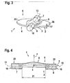
- FIG. 3 is the side view of a slightly tilted throttle according to the present invention can be seen.
- FIG. 3 shows that on both sides of the groove 9 on the downstream side of its first surface area 25 and a second surface area 26 extend.
- the first surface region 25 and the second surface region 26 are in communication with one another via the material of the flap surface deformed by the groove 9, wherein the material thickness 17 in the region of the first surface region 25, within the second surface region 26 and in the region of the formation 8 or 9 in FIG Is essentially the same.
- the substantially planar formed first and second surface regions 25, 26 merge into one another in the region of the groove 9, ie in the region of the formation on the flap surface 2 of the throttle flap 1, and form a stiffening with regard to the flexural strength of the throttle flap element 1 proposed according to the invention.
- the formation 8 or 9 between the first surface region 25 and the second surface region 26 makes it possible to dispense with a continuous throttle shaft since the stiffening with respect to the true bending moment of the first surface region 25 and the second surface region 26 of the flap surface 2 by the formation. 8 , 9 is applied and thus makes the formation of a continuous throttle shaft obsolete.
- the throttle valve 1 is preferably manufactured as an injection molding component in one operation within a molding tool.
- the flow of plastic melt within the closed mold can be assisted by flow aids.
- one or more rib-shaped flow aids can be mounted in the convex design 8 in the area 2. These are located inside the Ausformungs Kunststoffes in the flap surface 2.
- corresponding negative molds can be provided on the injection molds. The flow aids are not visible from the inflow side 4 of the surface area 2.
- FIG. 4 produced with a coordinate system shown throttle valve 1 in one operation.
- FIG. 4 is a distance 21, in which the facing end faces of the first pin 6 and the second pin 7 are opposite. Within the distance 21, the required with regard to the bending moments due to the flow of the throttle flap surface 1 strength of the throttle valve is applied exclusively by the formation in the flap surface 2, without the need for a ribbing on the inflow side 4 and the downstream side 5 of the flap surface 2.
- the peripheral surfaces of the first pin 6 and the second pin 7, in which the inventively proposed throttle wall of an intake air or charge air duct is received, is designated by reference numeral 22, while the outer side end faces of the first pin 6 and the second pin. 7 indicated by the reference numeral 16 are.
- Perpendicular to the drawing plane according to FIG. 4 extends the X-axis of in FIG. 4 shown coordinate system in the spatial directions x, y and z.
- FIG. 5 shows the top view of the throttle valve according to FIG. 1 .
- the Z-axis of the coordinate system in the spatial directions X, Y and Z extends perpendicular to the plane of the drawing, while the course of the Y-axis coincides with the line of symmetry 13 of the throttle valve 1.
- the X-axis extends in the radial direction with respect to the flap surface 2 of the throttle valve 1.
- the injection point for the formed in the area 2 in a convex shape 8 coincides with the origin of the Z-axis of the coordinate system. From this injection point, the plastic melt flows within the mold, supported by the flow aids formed in the molding tool in the radial direction and forms the surface region 2 with a curved shaped molding 8 in consistently uniform material thickness.
- the representation according to FIG. 5 can be taken that the curvature curve 28 is parallel to the axis of symmetry 13 of the throttle valve 1, wherein the axis of symmetry 13 of the throttle valve 1 as shown in FIG FIG. 5 coincides with the pivot axis of the throttle surface 2.
- the sublime from the drawing level according to FIG. 5 The protruding formation 8 is characterized by a uniform course with respect to the axial extension of the axis of symmetry 13, the formation 8 assuming its maximum in the region of the Z-axis protruding from the plane of the drawing according to FIG. 5 with respect to the line of symmetry 13 of the throttle flap 1 (see FIG Representation according to FIG. 4 ).
- the representation according to FIG. 6 is the intersection VI - VI according to FIG. 5 refer to.
- the Z-axis of the coordinate system in the three spatial directions x, y, z is perpendicular, while the X-axis extends into the horizontal.
- the in FIG. 6 illustrated sectioning through the flap surface 2 of the throttle valve 1 according to FIG. 5 passes through the second transition region 11 as shown in FIG FIG. 5 .
- From the illustration according to FIG. 6 shows that the material thickness 17 viewed in the direction of the X-axis, in the first area 25 and in the region of the formation 8, 9 and within the second area 24 of the throttle valve 1 is substantially constant.
- the limited by the end face of the second pin 7 groove 9 is according to the section line VI-VI in FIG.
- the radius of curvature 15 of the groove 9 on the downstream side of the throttle damper 1 is greater than the first radius of curvature 14 in the region of the groove 9 delimited by the end face of the second stud.
- the course of the radius of curvature is the same as that shown in FIG FIG. 5 from the Z-axis assigning end face of the second pin 7 continuously to the cutting plane 7 as shown in FIG. 5 to decrease continuously from there along the Y-axis in the direction of the z-axis assigning end face of the first pin 6.
- the curvature profile 28 takes in the region of the sectional plane characterized by a semicircular curvature in the plate surface of Drosselelldappe 1, which is defined in the sectional plane VI-VI by the further radius of curvature 15, which in the illustration according to FIG. 6 was selected as an example.
- FIG. 7 has the-Schnittverlauf VII-VII according to the plan view of the throttle valve in FIG. 5 ,
- section profile VII-VII shows that the radius of curvature of the groove 9 in the Z-axis assumes its maximum value.
- the maximum radius of curvature 27 in the illustration according to FIG. 7 For example, the throttle valve 1 on the inflow side 4, the largest deformation, ie the curvature curve 28 of the flap surface of the throttle valve 1 assumes its maximum here.
- Due to the in FIG. 5 illustrated transition regions on both sides of the position of the maximum radius of curvature 27 is achieved by the formation 8, 9 in the flap surface of the throttle valve 1 an immense flexural rigidity improvement of the throttle valve 1.
- One the flap surface of the Throttle valve 1 stiffening, continuously extending throttle shaft can now be omitted, so that in FIG. 5 shown first pin 6 and second pin 7 sufficient as storage locations for the inventively shaped throttle valve 1.
- the second transition region 11 within which the radius of curvature steadily increases from a value corresponding to the first radius of curvature 14 to a value corresponding to the maximum radius of curvature 27, seen continuously within the first transitional range 10 in the Y direction, again from the maximum radius of curvature 27 on the first radius of curvature 14 at the z-axis zu josde Stirnseite- the first pin 6 fall.
- the selected contour of the shape in the flap surface of the throttle valve 1 a substantially parallel to the axis of symmetry 13 of the throttle valve 1 extending stiffening structure is created.
- the stiffening effect of the shape 8, 9 in the flap surface of the throttle valve 1 makes reinforcing ribs on the inflow side 4 and the outflow side 5 of the throttle valve 1 unnecessary.
- the material thickness 17 within the first surface area 25, which is formed essentially planar and the shape 8, 9 in the flap surface of the throttle valve 1 and within the second area 26 substantially constant, so that accumulations of material both in the flap surface in all three spatial directions x , y, - z are minimized.
- the flap surface 2 of the throttle valve 1, which is preferably manufactured as Spritzg tellbauteil, is bounded by a border 3, which conforms to the not shown wall of Ansaug poverty- or Aufladeluftkanals an internal combustion engine depending on the pivot position of the throttle about its axis of symmetry 13.
- the flexural strength of the inventively proposed throttle for use in the intake / charge air duct of an internal combustion engine, not shown here can be influenced by the shape of the formation 8 and 9 and by the shape of the curvature curve 28 parallel to the axis of symmetry 13 of the throttle valve 1.
- the transition regions 10 and 11, on both sides of the Z-axis as shown in FIG. 5 For example, they can also be larger than those in FIG. 6 respectively.
- FIG. 7 formed radii of curvature are formed.
- a bending stiffness improvement of the throttle valve element 1 proposed according to the invention can also be achieved by selecting the plastic material to be injected into the molding tool.
- a uniform flow of the plastic material injected as a plastic melt into the molding tool can be achieved by flow aids arranged in the region of the molding, which can be designed in the form of rib-shaped channels.
- the flow aids are located on the side facing away from the inflow 4 side of the surface area 2 of the throttle valve. 1
- the transition regions 10 and 11 contains both sides of the Z-axis
- the convex curved in the flap surface 2 of the throttle valve 1 executed Ausformung 8 also without transition regions 10 and 11 respectively be.
- the convexly curved shape 8 extends in the flap surface 2 of the throttle valve 1 over the entire flap surface 2, without flat surface areas are formed in the flap surface 2 except a flat ring on the edge of the flap surface 2.
Landscapes
- Engineering & Computer Science (AREA)
- General Engineering & Computer Science (AREA)
- Mechanical Engineering (AREA)
- Chemical & Material Sciences (AREA)
- Combustion & Propulsion (AREA)
- Lift Valve (AREA)
- Control Of Throttle Valves Provided In The Intake System Or In The Exhaust System (AREA)
Claims (11)
- Volet d'étranglement destiné à un moteur à combustion interne comportant un premier palier et un second palier (6, 7), avec des zones de surface (25, 26) pratiquement planes, s'étendant de part et d'autre de son axe de symétrie (13), et délimitée chacune par une périphérie (3), le volet d'étranglement étant réglable autour de son axe de symétrie (13) par un moyen d'entraînement,
les zones de surface (25, 26) de forme plane étant reliées par une déformation (8, 9, 28) bombée dans la surface du volet d'étranglement, parallèle à l'axe de symétrie (13),
caractérisé en ce que
la surface (2) du volet comporte un premier tourillon (6) et un second tourillon (7). - Volet d'étranglement selon la revendication 1,
caractérisé en ce que
la déformation (8, 9, 28) comporte une première zone transitoire (10) et une seconde zone transitoire (11). - Volet d'étranglement selon la revendication 2,
caractérisé en ce que
la déformation (8, 9, 28) présente un tracé croissant ou décroissant (28) pour le rayon de courbure (14, 15, 27) dans la zone transitoire (10, 11). - Volet d'étranglement selon la revendication 2,
caractérisé en ce que
la déformation (8, 9, 28) possède son rayon de courbure (27) maximum sensiblement au milieu entre les zones transitoires (10, 11). - Volet d'étranglement selon la revendication 2,
caractérisé en ce que
la déformation (8, 9, 28) présente une zone bombée (8) sur le côté amont (4) du volet d'étranglement et une cavité (9) sur le côté aval (5) du volet d'étranglement. - Volet d'étranglement selon la revendication 1,
caractérisé en ce que
l'épaisseur (17) de la matière de la surface (2) du volet d'étranglement dans la zone de surface plane (25, 26) et dans la déformation (8, 9, 28) est pratiquement constante. - Volet d'étranglement selon la revendication 1,
caractérisé en ce que
le point d'injection de la matière plastique fondue, fluide se situe à l'origine d'un système de coordonnées (X, Y, Z) sous-tendu par la surface (2) du volet. - Volet d'étranglement selon la revendication 1,
caractérisé en ce que
les tourillons (6, 7) s'étendent parallèlement à l'axe de symétrie (13) sur la surface (2) du volet. - Volet d'étranglement selon la revendication 1,
caractérisé en ce que
les tourillons (6, 7) limitent la déformation (8, 9, 28) et leurs faces frontales tournées vers la déformation (8, 9, 28) sont écartées de la distance (21). - Volet d'étranglement selon la revendication 1,
caractérisé en ce que
la déformation (8, 9, 28) est continue avec une courbure constante parallèle à l'axe de symétrie (13) du volet d'étranglement qui coïncide avec son axe de basculement. - Volet d'étranglement selon la revendication 1,
caractérisé en ce qu'
il est réalisé sous la forme d'une pièce injectée.
Applications Claiming Priority (3)
| Application Number | Priority Date | Filing Date | Title |
|---|---|---|---|
| DE2002125671 DE10225671A1 (de) | 2002-06-10 | 2002-06-10 | Biegemomentoptimiertes Drosselklappenelement |
| DE10225671 | 2002-06-10 | ||
| PCT/DE2002/004477 WO2003104632A1 (fr) | 2002-06-10 | 2002-12-06 | Element de papillon des gaz a couple de flexion optimise |
Publications (2)
| Publication Number | Publication Date |
|---|---|
| EP1516111A1 EP1516111A1 (fr) | 2005-03-23 |
| EP1516111B1 true EP1516111B1 (fr) | 2008-08-20 |
Family
ID=29718923
Family Applications (1)
| Application Number | Title | Priority Date | Filing Date |
|---|---|---|---|
| EP02794974A Expired - Lifetime EP1516111B1 (fr) | 2002-06-10 | 2002-12-06 | Element de papillon des gaz a couple de flexion optimise |
Country Status (4)
| Country | Link |
|---|---|
| EP (1) | EP1516111B1 (fr) |
| JP (1) | JP2005529277A (fr) |
| DE (2) | DE10225671A1 (fr) |
| WO (1) | WO2003104632A1 (fr) |
Families Citing this family (1)
| Publication number | Priority date | Publication date | Assignee | Title |
|---|---|---|---|---|
| DE102010023412B4 (de) * | 2010-06-11 | 2012-05-24 | Pierburg Gmbh | Klappenvorrichtung für eine Verbrennungskraftmaschine |
Family Cites Families (9)
| Publication number | Priority date | Publication date | Assignee | Title |
|---|---|---|---|---|
| US2529572A (en) * | 1946-01-15 | 1950-11-14 | Weatherhead Co | Carburetor valve |
| US4943404A (en) * | 1987-11-13 | 1990-07-24 | Phillips Petroleum Company | Process for producing a fiber reinforced thermoplastic article |
| AT410245B (de) | 1993-07-14 | 2003-03-25 | Bosch Gmbh Robert | Aus kunststoff bestehender formkörper |
| DE4329522A1 (de) | 1993-09-02 | 1995-03-09 | Mann & Hummel Filter | Drosseleinrichtung |
| JPH0814407A (ja) * | 1994-06-28 | 1996-01-16 | Fuji Oozx Inc | バタフライバルブ |
| DE19525510B4 (de) | 1995-07-13 | 2008-05-08 | Robert Bosch Gmbh | Drosselklappenstelleinheit |
| DE19914994A1 (de) | 1998-04-03 | 1999-10-14 | Advantest Corp | Verfahren und Vorrichtung zur Oberflächenprüfung |
| US6354267B1 (en) * | 2000-03-28 | 2002-03-12 | Borgwarner Inc. | Injection molded throttle body |
| DE10055397A1 (de) * | 2000-11-09 | 2002-05-29 | Albert Handtmann Metallguswerk | Vorrichtung mit mindestens einer Drosselklappe und Verfahren zum Herstellen dieser Vorrichtung |
-
2002
- 2002-06-10 DE DE2002125671 patent/DE10225671A1/de not_active Ceased
- 2002-12-06 EP EP02794974A patent/EP1516111B1/fr not_active Expired - Lifetime
- 2002-12-06 JP JP2004511678A patent/JP2005529277A/ja active Pending
- 2002-12-06 DE DE50212690T patent/DE50212690D1/de not_active Expired - Lifetime
- 2002-12-06 WO PCT/DE2002/004477 patent/WO2003104632A1/fr not_active Ceased
Also Published As
| Publication number | Publication date |
|---|---|
| WO2003104632A1 (fr) | 2003-12-18 |
| DE10225671A1 (de) | 2004-01-08 |
| DE50212690D1 (de) | 2008-10-02 |
| JP2005529277A (ja) | 2005-09-29 |
| EP1516111A1 (fr) | 2005-03-23 |
Similar Documents
| Publication | Publication Date | Title |
|---|---|---|
| EP1281847B1 (fr) | Unité de vanne d'étranglement avec vanne d'étranglement intégrée | |
| DE69318326T2 (de) | Brennkraftmaschine mit geschichteter Ladung | |
| EP2497919B1 (fr) | Châssis de ventilateur et procédé de fabrication d'un châssis de ventilateur en plastique, en particulier pour refroidisseur de véhicule automobile | |
| DE102009059143B4 (de) | Zweitaktmotor und Sandkern zur Herstellung eines Zweitaktmotors | |
| DE69604084T2 (de) | Drosselklappenkörper mit ansaugkanal mit progressiv änderndem profil auf einer seite und drosselklappe mit progressiv änderndem profil auf der komplementären seite | |
| DE102004056764B4 (de) | Drosselkörper und Verfahren zum Herstellen solcher Drosselkörper | |
| WO2000065214A1 (fr) | Ensemble volets de commande constitue de volets de commande, moules par injection au moment du montage, ou de modules a volets | |
| EP0468322A1 (fr) | Capotage de moteur de véhicule | |
| EP1200721B1 (fr) | Soupape | |
| DE2501305A1 (de) | Luftansauganlage fuer brennkraftmaschinen | |
| EP1371832A1 (fr) | Valve à papillon ayant l'axe surenjecté | |
| EP3743257B1 (fr) | Moule d'injection destiné à la fabrication de pièces moulées complexes en plastique | |
| EP1200722B1 (fr) | Dispositif d'etranglement a volet destine au montage dans une jonction a brides | |
| EP1298299B1 (fr) | Dispositif d'étranglement avec des éléments de boîtiers échangeables | |
| DE2423383B2 (de) | Umwälzpumpe | |
| DE102010054839B4 (de) | Zweitaktmotor | |
| DE202007013151U1 (de) | Ansaugsystem für eine Brennkraftmaschine | |
| EP1420938B1 (fr) | Procede de fabrication d'un boitier tubulaire de clapet d'etranglement et d'un clapet d'etranglement | |
| DE10143384C1 (de) | Schaltklappeneinrichtung | |
| WO2003104632A1 (fr) | Element de papillon des gaz a couple de flexion optimise | |
| DE69707415T2 (de) | Staubsaugergehäuse mit minimierter anzahl von richtungen zum lösen aus einer gussform | |
| EP4344848B1 (fr) | Corps creux moulé par injection, dispositif pour sa fabrication et distributeur de fluide réglable comprenant un tel corps creux | |
| EP1714018B1 (fr) | Dispositif etrangleur | |
| EP1447603B1 (fr) | Soupape à papillon et procédé pour la produire | |
| DE102004030555B4 (de) | Einlasskanal eines Motors mit magerer Verbrennung und Kern zur Herstellung desselben |
Legal Events
| Date | Code | Title | Description |
|---|---|---|---|
| PUAI | Public reference made under article 153(3) epc to a published international application that has entered the european phase |
Free format text: ORIGINAL CODE: 0009012 |
|
| 17P | Request for examination filed |
Effective date: 20050110 |
|
| AK | Designated contracting states |
Kind code of ref document: A1 Designated state(s): AT BE BG CH CY CZ DE DK EE ES FI FR GB GR IE IT LI LU MC NL PT SE SI SK TR |
|
| RBV | Designated contracting states (corrected) |
Designated state(s): DE FR IT SE SI SK TR |
|
| GRAP | Despatch of communication of intention to grant a patent |
Free format text: ORIGINAL CODE: EPIDOSNIGR1 |
|
| GRAS | Grant fee paid |
Free format text: ORIGINAL CODE: EPIDOSNIGR3 |
|
| GRAA | (expected) grant |
Free format text: ORIGINAL CODE: 0009210 |
|
| AK | Designated contracting states |
Kind code of ref document: B1 Designated state(s): DE FR IT |
|
| REF | Corresponds to: |
Ref document number: 50212690 Country of ref document: DE Date of ref document: 20081002 Kind code of ref document: P |
|
| PLBE | No opposition filed within time limit |
Free format text: ORIGINAL CODE: 0009261 |
|
| STAA | Information on the status of an ep patent application or granted ep patent |
Free format text: STATUS: NO OPPOSITION FILED WITHIN TIME LIMIT |
|
| 26N | No opposition filed |
Effective date: 20090525 |
|
| PGFP | Annual fee paid to national office [announced via postgrant information from national office to epo] |
Ref country code: FR Payment date: 20131213 Year of fee payment: 12 Ref country code: IT Payment date: 20131219 Year of fee payment: 12 |
|
| REG | Reference to a national code |
Ref country code: FR Ref legal event code: ST Effective date: 20150831 |
|
| PG25 | Lapsed in a contracting state [announced via postgrant information from national office to epo] |
Ref country code: FR Free format text: LAPSE BECAUSE OF NON-PAYMENT OF DUE FEES Effective date: 20141231 |
|
| PG25 | Lapsed in a contracting state [announced via postgrant information from national office to epo] |
Ref country code: IT Free format text: LAPSE BECAUSE OF NON-PAYMENT OF DUE FEES Effective date: 20141206 |
|
| PGFP | Annual fee paid to national office [announced via postgrant information from national office to epo] |
Ref country code: DE Payment date: 20170224 Year of fee payment: 15 |
|
| REG | Reference to a national code |
Ref country code: DE Ref legal event code: R119 Ref document number: 50212690 Country of ref document: DE |
|
| PG25 | Lapsed in a contracting state [announced via postgrant information from national office to epo] |
Ref country code: DE Free format text: LAPSE BECAUSE OF NON-PAYMENT OF DUE FEES Effective date: 20180703 |