EP1515587A1 - Elektrische Heizvorrichtung mit versiegeltem Heizelement - Google Patents
Elektrische Heizvorrichtung mit versiegeltem Heizelement Download PDFInfo
- Publication number
- EP1515587A1 EP1515587A1 EP03020700A EP03020700A EP1515587A1 EP 1515587 A1 EP1515587 A1 EP 1515587A1 EP 03020700 A EP03020700 A EP 03020700A EP 03020700 A EP03020700 A EP 03020700A EP 1515587 A1 EP1515587 A1 EP 1515587A1
- Authority
- EP
- European Patent Office
- Prior art keywords
- housing
- heating device
- contact plate
- electric heating
- spring
- Prior art date
- Legal status (The legal status is an assumption and is not a legal conclusion. Google has not performed a legal analysis and makes no representation as to the accuracy of the status listed.)
- Granted
Links
Images







Classifications
-
- F—MECHANICAL ENGINEERING; LIGHTING; HEATING; WEAPONS; BLASTING
- F24—HEATING; RANGES; VENTILATING
- F24H—FLUID HEATERS, e.g. WATER OR AIR HEATERS, HAVING HEAT-GENERATING MEANS, e.g. HEAT PUMPS, IN GENERAL
- F24H3/00—Air heaters
- F24H3/02—Air heaters with forced circulation
- F24H3/04—Air heaters with forced circulation the air being in direct contact with the heating medium, e.g. electric heating element
- F24H3/0405—Air heaters with forced circulation the air being in direct contact with the heating medium, e.g. electric heating element using electric energy supply, e.g. the heating medium being a resistive element; Heating by direct contact, i.e. with resistive elements, electrodes and fins being bonded together without additional element in-between
- F24H3/0429—For vehicles
-
- B—PERFORMING OPERATIONS; TRANSPORTING
- B25—HAND TOOLS; PORTABLE POWER-DRIVEN TOOLS; MANIPULATORS
- B25C—HAND-HELD NAILING OR STAPLING TOOLS; MANUALLY OPERATED PORTABLE STAPLING TOOLS
- B25C5/00—Manually operated portable stapling tools; Hand-held power-operated stapling tools; Staple feeding devices therefor
- B25C5/02—Manually operated portable stapling tools; Hand-held power-operated stapling tools; Staple feeding devices therefor with provision for bending the ends of the staples on to the work
- B25C5/0221—Stapling tools of the table model type, i.e. tools supported by a table or the work during operation
-
- B—PERFORMING OPERATIONS; TRANSPORTING
- B25—HAND TOOLS; PORTABLE POWER-DRIVEN TOOLS; MANIPULATORS
- B25C—HAND-HELD NAILING OR STAPLING TOOLS; MANUALLY OPERATED PORTABLE STAPLING TOOLS
- B25C5/00—Manually operated portable stapling tools; Hand-held power-operated stapling tools; Staple feeding devices therefor
- B25C5/10—Driving means
- B25C5/11—Driving means operated by manual or foot power
-
- F—MECHANICAL ENGINEERING; LIGHTING; HEATING; WEAPONS; BLASTING
- F24—HEATING; RANGES; VENTILATING
- F24H—FLUID HEATERS, e.g. WATER OR AIR HEATERS, HAVING HEAT-GENERATING MEANS, e.g. HEAT PUMPS, IN GENERAL
- F24H9/00—Details
- F24H9/18—Arrangement or mounting of grates or heating means
- F24H9/1854—Arrangement or mounting of grates or heating means for air heaters
- F24H9/1863—Arrangement or mounting of electric heating means
- F24H9/1872—PTC resistor
-
- H—ELECTRICITY
- H05—ELECTRIC TECHNIQUES NOT OTHERWISE PROVIDED FOR
- H05B—ELECTRIC HEATING; ELECTRIC LIGHT SOURCES NOT OTHERWISE PROVIDED FOR; CIRCUIT ARRANGEMENTS FOR ELECTRIC LIGHT SOURCES, IN GENERAL
- H05B3/00—Ohmic-resistance heating
- H05B3/10—Heating elements characterised by the composition or nature of the materials or by the arrangement of the conductor
- H05B3/12—Heating elements characterised by the composition or nature of the materials or by the arrangement of the conductor characterised by the composition or nature of the conductive material
- H05B3/14—Heating elements characterised by the composition or nature of the materials or by the arrangement of the conductor characterised by the composition or nature of the conductive material the material being non-metallic
-
- H—ELECTRICITY
- H05—ELECTRIC TECHNIQUES NOT OTHERWISE PROVIDED FOR
- H05B—ELECTRIC HEATING; ELECTRIC LIGHT SOURCES NOT OTHERWISE PROVIDED FOR; CIRCUIT ARRANGEMENTS FOR ELECTRIC LIGHT SOURCES, IN GENERAL
- H05B3/00—Ohmic-resistance heating
- H05B3/40—Heating elements having the shape of rods or tubes
- H05B3/42—Heating elements having the shape of rods or tubes non-flexible
- H05B3/48—Heating elements having the shape of rods or tubes non-flexible heating conductor embedded in insulating material
- H05B3/50—Heating elements having the shape of rods or tubes non-flexible heating conductor embedded in insulating material heating conductor arranged in metal tubes, the radiating surface having heat-conducting fins
-
- H—ELECTRICITY
- H05—ELECTRIC TECHNIQUES NOT OTHERWISE PROVIDED FOR
- H05B—ELECTRIC HEATING; ELECTRIC LIGHT SOURCES NOT OTHERWISE PROVIDED FOR; CIRCUIT ARRANGEMENTS FOR ELECTRIC LIGHT SOURCES, IN GENERAL
- H05B2203/00—Aspects relating to Ohmic resistive heating covered by group H05B3/00
- H05B2203/02—Heaters using heating elements having a positive temperature coefficient
Definitions
- the invention relates to an electric heater, in particular as additional heating for motor vehicles, a structural unit for such a heating device and a corresponding Production method.
- Electric auxiliary heaters are used to heat the interior and engine.
- electric heaters are also for other purposes suitable, for example in the field of home installations, in particular Room air conditioning, in industrial plants and the like.
- PTC heating elements used with radiator elements in thermally conductive connection.
- the of The heat generated by the PTC heating elements is transmitted to the flowing through the radiator elements Air discharged.
- the overall arrangement of a layered structure of PTC heating elements, radiator elements and contact plates, the power supply serve is to increase the efficiency of the heating in a clamping pressure kept in a frame. Due to the clamping is a high electrical and thermal Contacting of the PTC heating elements achieved.
- the layered structure is in a stable frame with preferably U-shaped Cross section held.
- the frame is designed so that it is the layered Construction compresses.
- the clamping may alternatively be effected by spring elements which are arranged in the layered structure. So that the frame the spring forces it can be mechanically very stable, preferably with one U-shaped cross section formed.
- a conventional heater is for example from DE-A-101 21 568.
- the minimum height of the longitudinal beams of such a frame with U-shaped cross-section is in the required Clamping forces in about 11 mm. This results in one for the entire heater Non-usable height of at least 22 mm.
- Such a design with external clamping or outside holding frame thus has a high surface area, which is not available for the air flow. For this reason are such electric heaters for use at very low installation heights not suitable.
- metal support frames Another disadvantage of metal support frames is their conductive surface. To the Increasing safety in motor vehicles, metal surfaces are increasing in increasing Dimensions are avoided so that their touch is safely possible, i. E. without electrical or thermal line.
- the heating devices described above are preferred provided with a plastic envelope, such as in DE-A-101 21 568 heater shown.
- the object of the invention is an electric heater, a structural unit for a electric heating device and a manufacturing method for an electric heater having an improved structure, the above-mentioned Disadvantages not owns.
- the electric heater in the manufacture of the electric heater first one of the contact plates, which contact the PTC heating element, with a lacquer layer Mistake. About this paint layer, the PTC heating element "provisionally" on the Contact plate fixed and sealed.
- Such a heater has several advantages.
- the additional effect On the electrode applied paint layer a more extensive corrosion protection than Conventionally achievable.
- the paint protects the contact plate and the connection between PTC element and contact plate against moisture penetration. A corrosion over Moisture with which the contact plate during manufacture or during operation in Touch comes, is excluded.
- the lacquer coating is applied to the PTC heating elements during the manufacturing process facing side of an electrode applied. Then be positioned on the paint layer, the PTC heating elements. By the spring element caused clamping pressure is between the PTC element and the contact plate Existing paint largely expelled. The pressed-out varnish seals over a bead the space between the PTC heating element and the contact plate from. About this sealing of the transition between the electrode and the PTC heating element is an efficient corrosion protection possible.
- the invention enables a simplified production of such electrical Heater.
- the prefabricated units are the PTC heating elements held over the paint at predetermined positions on the contact plate.
- the paint is an electrically non-conductive paint.
- the reliability of the heater is increased because exposed Metal surfaces are avoided.
- a silicone varnish used for this purpose.
- Such a silicone varnish is not only electrically non-conductive, but also capable of different coefficients of expansion of the PTC heating element and the contact sheet, which is preferably made of aluminum, compensate. It is therefore particularly advantageous to use an elastic paint.
- a highly viscous lacquer is used.
- the paint has a viscosity lower than 900 mPa.s.
- Such a paint can therefore be processed particularly easily, for example, is a simple paint job by a brush or stripping coating, in particular by a drip coating via standard dosing devices, possible. This way you can the manufacture of prefabricated units are particularly simplified.
- a further simplification of the production can be achieved by the prefabricated units from a radiator element, one attached to this Contact plate and on this over the paint attached PTC heating elements. With such a larger prefabricated unit, the production can be further simplify and accelerate.
- the contact plate on which the PTC heating element fastened over the paint made of aluminum. With this material allows a particularly good heat transfer between the PTC heating element and reach the radiator element.
- the elongated end faces are formed mechanically particularly stable and can therefore absorb particularly high forces.
- the elongated end faces are in openings the elongated end faces for the air flowing through cross braces provided which absorb the clamping forces generated by the spring element. In this way are high clamping forces at low height and much lighter materials such Plastic possible.
- electrical heating devices be used more diverse, especially at low levels available standing height.
- struts are in addition to the cross braces provided in the openings of the housing sides longitudinal struts, so that the struts form a lattice structure. This allows the struts even be kept particularly thin, so that they only slightly affect the air flow obstruct and still prevent bending of the housing effectively.
- One Housing for an electric heater is thus in a simple manner from a lightweight and also easy to process material such as plastic produced.
- the longitudinal struts are arranged so that they are located in the area of the PTC heating elements.
- the struts are so placed to coincide with sections where there is no airflow.
- the housing is made of plastic.
- a major advantage of a Plastic housing lies in its low weight, its flexible formability and its low production costs. With this material you can save the costs a heater can be kept very low.
- the housing has a lateral Opening for insertion of the spring element after assembly of the heater. This makes the production of such a heater much easier, There are no special devices to overcome the spring forces during assembly required are.
- the spring is inserted into the housing only when the composite housing is able to withstand the forces generated by the spring To compress the layered structure.
- the Spring guided in a groove.
- the housing is composed of two half-shells. This is a particularly simple assembly of the heater possible.
- the half shells are designed to be plugged together.
- locking pins or locking lugs which when plugging the half shells cause a locking of both half shells of the housing, is a special faster assembly possible.
- Both half-shells are preferably designed so that they approximately surround the housing separate centrally between the opposite, open housing sides.
- the housing is particularly stable on the open sides only in the middle, i. at the dividing line of both half-shells, the housing can not or record only small clamping forces.
- the two half-shells are at their parting lines provided with additional projections and depressions, which when mating interlock and interlock the half-shells.
- the housing can so also in the middle range, at the dividing lines of both half-shells, absorb higher forces.
- the projections and depressions entangle both half shells together and thereby cause an increase in the mechanical stability of the side surfaces. With such a construction, high clamping forces can also be applied to housing materials be used with a fundamentally lower stability.
- the spring element is designed so that it has the clamping forces substantially on the reinforced trained housing sides transmits.
- the spring element preferably consists of a sheet metal part with obliquely protruding Spring segments.
- the spring element with the spring segments integrally formed.
- the spring can be produced for the first time as an endless part and be supplied in a simple manner from a role of manufacturing. conventional on the other hand, each spring must be manufactured separately and individually for different lengths getting produced.
- the spring element of the heating device according to the invention is in contrast, easily cut from roll to any length, so that elaborate individual manufacturing processes for the spring and adjustments to the manufacturing process be avoided when changing the structure of the heating element.
- the thickness of the springs of conventional about 0.8 mm according to the new construction principle to a thickness of about 0.3 mm be reduced.
- the spring can be produced with little effort, without the efficiency of the heater is reduced.
- a particularly high efficiency can be achieved by increasing the clamping forces, if provided in the region of a PTC heating element, a plurality of spring segments is, preferably two or three individual spring segments. This will make each one PTC heating element kept clamped along its entire length.
- the springs consist of a Sheet metal, from which obliquely projecting individual spring segments in the transverse direction, the Mechanically reinforce the spring so that there is a deflection around the longitudinal axis of the spring not possible.
- the spring segments each extend into the edge area the spring, so that the spring supported on the stable outer edge of the housing can.
- the housing must therefore absorb forces only at its edges and can be made less stable in the middle. This is a special way Use lightweight and easy-to-use housing material.
- the electric heater is between the longitudinal struts and the layered structure provided a seal.
- a seal in particular as a silicone seal, is preferably in one piece trained and seals the entire grid structure.
- the PTC heating elements via Positioning means, such as a position frame between contact plates be positioned, according to the invention electric heaters so manufactured, that at least one of the contact plates is provided with a lacquer layer and on this the PTC heating elements before mounting in the electric heater be positioned.
- Positioning means such as a position frame between contact plates be positioned
- electric heaters so manufactured, that at least one of the contact plates is provided with a lacquer layer and on this the PTC heating elements before mounting in the electric heater be positioned.
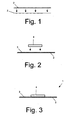
- Fig. 1 shows a schematic view of the side view of a contact plate 2, with a paint layer 3 on the side facing the PTC heating laterally provided becomes. On this paint layer 3, the PTC heating element 4 is then placed ( Figure 2).
- the contact plate 2 with the lacquer layer 3 and the PTC heating element arranged thereon 4 form a prefabricated structural unit 1, which is shown schematically in FIG is.
- the strength of the fixation of PTC heating elements 4 via the paint 3 on the contact plate is designed to withstand mechanical stresses that occur during and during manufacture an electric heater occur, sufficiently withstand. Stronger mechanical stress does not withstand this fixation.
- about such Lacquer layer 3, on which the PTC heating elements 4 are placed can the production electrical heaters are significantly simplified. In particular, over the thus prefabricated units 1 reduces the number of parts to be assembled become. In addition, the assembly is simplified because no tedious positioning the individual elements in a housing is required. In addition, there are no positioning means required, because the PTC heating elements at certain on Be held in position.
- a particular advantage achieved by the paint is improved moisture protection.
- the achievable during assembly of the heater additional seal the compound PTC heating element 4 and contact plate 2 is below. Referring to Fig. 5 described.
- FIG. 4 A variant of a prefabricated unit is shown in Fig. 4. At the contact plate 2, a radiator element 5 is additionally attached.
- This prefabricated unit in which on the contact plate 2, a PTC heating element 4 according to that in the figures 1 to 3 illustrated manufacturing process is attached, allows further reduction the assembly steps required in the fabrication of an electric heater, since a separate insertion of the radiator elements 5 is omitted.
- FIG. 4 When installing the prefabricated unit 1 according to the invention (as shown in FIG. 4) into a Housing of the heater, the individual elements of the heater after Insertion of a spring element (not shown in Figures 1 to 8) via a Clamping held under a bias.
- a section of an inventive electric heating device that represents the clamping pressure and its effect, is shown in FIG.
- FIG. 5 shows, in addition to the prefabricated structural unit 1 from FIG. 4, radiator element 5, contact plate 2, paint layer 3 and PTC heating element 4 a to the PTC heating element 4 subsequent contact plate 10 and this adjacent another Radiator 11.
- the pressure caused by the clamping pressure is by black arrows in Fig. 5 symbolizes.
- the contact pressure causes the between the PTC heating element 4 and the contact plate 2 located paint 3 on the sides of the Gap 13 between the PTC heating element 4 and the contact plate 2 pressed out becomes.
- the extruded from the gap 13 paint forms on the outer Edges of the gap 13 Lackwülste 12, the gap 13 against seal in penetrating moisture.
- the heating device according to the invention is about the coating of the contact plate with a lacquer layer and the resulting sealing of the contact point PTC heating element and contact sheet in an efficient manner against moisture damage, in particular Corrosion, and associated power loss protected.
- the Heating device according to the invention is thus particularly for extreme conditions suitable, in which the danger is particularly great that the heater with moisture comes into contact.
- an electrically non-conductive paint is used for the paint 3.
- the paint is pressed out of the gap 13 and realized so an electrically conductive contact between the contact plate 2 and the PTC heating element 4th
- the thickness of the coating application is preferably in the range between 10 and 20 ⁇ l / cm 2 , particularly preferably in the range of 14 ⁇ l / cm 2 .
- the paint 3 is in a simple manner by a brush, stripping or drip coating coatable. This coating is made possible by a particularly high viscosity, which is preferably in the range of 900 mPa.s to 750 mPa.s. Especially preferable the paint has a viscosity of about 850 mPa.s.
- the paint forms a permanent Cover as protection against moisture and atmospheric contaminants.
- a high-viscosity paint is to be used. This is to increase the Environmental compatibility used a paint containing only a low proportion of solvents having.
- the contact plate 2 is made of aluminum. Aluminum allows a particularly good advertising transition between the PTC heating element 4 and the radiator element 5.
- the contact plate 10 which is the PTC heating element 4 on the contact plate 2 opposite side contacted, made of brass, preferably tinned Made of brass.
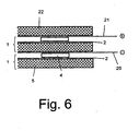
- Fig. 6 shows schematically a preferred embodiment for the clamped held components of the heating device according to the invention.
- the structure includes two prefabricated building units 1 each having at least one PTC heating element 4, a contact plate 2 and a radiator element 5.
- the structure comprises another contact plates 20, 21, which on the opposite sides of the PTC heating elements 4 abuts, and a final radiator element 22.
- the two contact plates 20 and 21 are at different potential.
- the internal structure shown in Fig. 6 comprises an advantageous embodiment of the heating element according to the invention only five components to be mounted, namely two prefabricated units 1, two contact plates 20, 21 and an additional Radiator element 22.
- Such a layered structure is thus particularly simple and easy to produce.
- FIGS. 7a and 7b is a perspective view and a sectional view of a preassembled unit 30 shown schematically.
- the assembly 30 consists of a radiator element 35 which is connected to a contact plate 32.
- a paint layer 33 is applied, via which the PTC heating elements 31 the contact plate 32 are fixed.
- Fig. 7a is a sectional view of the assembly 30 shown in a heating device is mounted under a clamping voltage. Due to the clamping pressure is between the PTC heating element 31 and the contact plate 32 located paint 33 laterally from the gap pushed out, so that he has the space above ridges 34, the so-called Adhesive meniscus, against the ingress of moisture and contaminants is sealed or sealed.
- the heater according to the invention of two plastic half shells built up. In the first production can be in a simple way Fit the housing half and then the housing by placing the completed second housing half. The installation of the electric heater will be described below with reference to Figures 12 to 15.
- FIGS. 8 to 10 various views of one of several layers are constructed electric heating device according to an embodiment of the present invention Invention shown.
- a sectional view through the electric heater is shown in FIG. 8
- FIG. 9 is a perspective view
- FIG. 10 is a plan view on the arranged in a half-shell of the housing components of the heater demonstrate.
- the housing consists of two interlocking half-shells 40a and 40b.
- the units of the invention are made of a Radiator 44, a contact plate 42 connected thereto and on the contact plate fixed heating elements 41 arranged.
- the units are each through Spacer 43 separately in one of the half-shells 40a, 40b used.
- each housing half-shell 40a, 40b are to reinforce the narrow housing longitudinal sides Provided reinforcing elements. In particular, grab when mating both housing halves 40a, 40b preferably latching tabs 46, 47 into each other. In this way, the narrow housing longitudinal sides are mechanically reinforced and can therefore absorb higher clamping forces. Details and alternatives for a mechanically reinforced training of the narrow housing sides are under With reference to the following figures explained.
- the clamping pressure is generated via a spring element 49, which is the layered structure composed of PTC elements 41, contact plates 42 and radiator elements 44, so that the electrical and thermal transition between the contact plates 42 and the PTC heating elements 41 is improved. This can increase the efficiency of the heater be increased.
- the PTC heating elements 41 are prepositioned on first contact plates 42 via a lacquer. On the opposite sides of the PTC heating elements 41 is during assembly another contact plate provided.
- About the contact tabs 50 of the led out Contact sheets are supplied to the electric heater during operation power.
- Fig. 11 The layered structure of a plurality of units, which in the housing 40th is used is shown in Fig. 11.
- FIGS. 12 to 15 show successive stages of the assembly of the invention Heating device, the structure of the heating device according to the invention clarify.
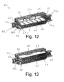
- FIG. 12 shows a perspective view of a half-shell 62 a of FIG Half shells 62a, 62b of the housing.
- a contact plate 66 In the half-shell 62a are a contact plate 66, a radiator element 64 and adjacent PTC heating elements 4 used.
- each guide rails or positioning intended for all components are each guide rails or positioning intended for all components.
- the radiator elements 64 are preferably in shape formed by corrugated rib elements.
- On one side is the corrugated fin element with provided a contact plate.
- For the ends of the contact plate of the corrugated fin element 64 are provided laterally in the inside of the housing guides 64 a. These guides serve only to facilitate assembly. in an alternative embodiment Therefore, they can be waived.
- the PTC heating elements 4 are again a radiator element 64 and a contact plate 67 with a plug contact 67a provided - accordingly to the structure shown in FIG.
- the second housing half-shell 62b can be plugged on. Both housing halves are preferably formed so that its dividing line is approximately in the middle between the two elongated Genzousestimrise (which have the passage openings) extends.
- the assembly of the housing can be simplified in particular by that both half-shells 62a, 62b with locking pin 78 and corresponding holes 79th are provided in each opposite half-shell. When mating Both half-shells lock as soon as the second half-shell 62b completely on the first Half shell 62a is attached.
- each of the housing halves 62a, 62b to the elongated end has openings for the air flowing through.
- the spring element 72 is at least inserted between a housing inside and the layered structure.
- such a spring element and between the opposite Housing inside and the layered structure or at a position within the layered structure can be inserted.
- the elongated Gerissausestimfact are mechanically reinforced. Between the mechanically reinforced Gerissausestim tone, especially in the area of Dividing line, the housing is unable to absorb high clamping forces.
- cross braces 69 In order to accommodate very high clamping forces are within the lateral Opening for the air to be heated cross braces 69 provided. These cross braces allow the housing to have sufficiently high clamping forces without a Can accommodate deflection or deformation of the housing.
- the half-shells with the struts are each integrally formed and preferably made of plastic produced.
- the cross braces 69 supplemented by one or more longitudinal struts 70, so that the struts 69 and 70 have the shape of a grid structure.
- Such a lattice structure allows that the cross braces 69 can be kept very thin and the air flow not hindered. At the same time effectively prevents bending of the housing.
- each half-shell 62a, 62b respectively have projections 76 and recesses 77 provided which are arranged so that they mate when mating to grab. In this way, the mechanical stability of the upper and lower sides by entanglement of the sides of the two half-shells also between the mechanical reinforced elongated housing sides increased.
- the spring element 72 after the Assembly of the housing can be used.
- the housing 62 on a housing side an opening 71.
- Such an opening is preferably on provided the narrow sides of the housing 62.
- Each housing half 62a, 62b has corresponding recesses, which in the composite housing 62 for Add slot 71 for insertion of the spring element 72.
- a special design the housing inner sides to form a spring channel for insertion of the spring element 72 will be described below with reference to FIGS. 21 to 23.
- the positioning means 64a, 66b, 67b provided in the housing are arranged such that that the prepositioned elements of the heater have sufficient space for leave the spring element.
- the prepositioned elements are in the fixed by the spring clamping direction with game fixed to keep it moving and to receive the clamping pressure generated by the spring.
- Fig. 15 it can be seen that the spring element 72 a plurality of individual spring segments has, which generate the clamping pressure. On preferred embodiments of the spring element 72 will be described below in connection with FIGS. 26a, 26b and 26c.
- the contact plates 66 and 67 are each outside arranged in the layered structure, so that the power supply via the Radiator 64 to the PTC heating elements 74 takes place.
- This structure leads to a particularly good heat transfer between the PTC heating elements 4 and the Radiator 64, which give the heat to the air flowing through, and heat conduction losses are therefore particularly low.
- the air flow is particularly little with special needs. This allows the height without reducing the air passage volume kept small.
- the clamping forces are not like conventionally received by the side rails of the support frame.
- the narrow sides of the housing can therefore be designed as desired.
- the housing narrow sides designed so that they have a mechanical fixation and an electrical Allow contacting the heater.
- For electrical contact is at least one housing narrow side to the geometry of a plug to Power supply customizable.
- FIGS. 12 to 15 The design of the narrow sides is shown by way of example in FIGS. 12 to 15.
- On the left side of the case is a plug shape from each of the two housing halves molded projections 73a, 73b formed. In this plug, the connector tabs protrude 66a and 67a of the two contact plates 66, 67 into it.
- On the opposite Side is a plug 74 from the projections 64 a, 64 b formed substantially the mechanical attachment of the electric heater is used. Because the Narrow sides of the housing 62 have to absorb high forces, they can be designed as desired for mechanical and / or electrical fastening.
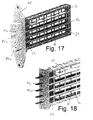
- FIGS. 16 to 18 show a further embodiment of a housing and a housing corresponding electric heating device shown.
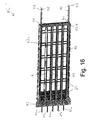
- Fig. 16 shows a perspective view View of an embodiment of an electric heater 80, opposite the embodiment of Figures 12 to 15 narrower, but with a larger cross-sectional area is designed for a higher air flow.
- the heater PTC heating elements 4 in a plurality of planes in the layered structure on.
- the PTC heating elements are 4, which have a rectangular shape, with their longitudinal sides parallel to aligned with the elongated Geotrousestimfact the heater.
- PTC heating elements 4 and electrode plates 81, 82 are each provided at the height of the layers with PTC heating elements 4 longitudinal struts 70.
- a total of four layers with PTC heating elements 4 present and accordingly also four longitudinal struts 70 are provided. Due to the greater longitudinal extent of the heater compared to Heater of Figures 12 to 15, this embodiment also has a larger Number of cross struts 69 on.
- Heating device uses two spring elements 72, each at the top and lower end to be inserted on the narrow side of the housing.
- the feathers are each inserted so that the spring segments 86, which consists of the spring element 72 protrude from the housing surface in the direction of the layered structure protrude.
- other spring elements 72 between pushed the two spring positions shown in the layered structure become.
- PTC heating elements 4 is also a correspondingly higher number of contact plates required.
- the uppermost and lowermost of the contact sheets 82 are adjacent to each arranged upper or lower housing inside.
- the three middle contact sheets are each arranged adjacent to the three lower layers with PTC heating elements, i.e. corresponding to the three lower of the longitudinal struts 70th
- Each of the contact sheets 81, 82 has protruding contact tongues from the frame 81a, 82a.
- the housing side 83, from which the contact tongues 81a, 82a protrude, can be configured arbitrarily.
- a particular embodiment is shown in FIG. 17.
- On the housing 83 shown in Fig. 16 is in each case an individually adapted plug shape 85 attached or glued. This glued plug form can be attached to the respective Be adapted to needs, for example, to install the heater in Vehicles of different car manufacturers, the different types of plug contacts use.
- the attachable Plug attachment 85 from a mechanical stop with mounting holes and a plug shoe 85a, in which the contact tongues 81a, 82a are arranged.
- transverse struts 69 of the lattice structure are at a distance of 30 to 40 mm arranged.
- the clamping forces can not be sufficient Measurements taken from the cross struts.
- Cross struts of less than 30 mm, in particular less than 20 mm, hinder this contrast, the air flow through the elongated ends of the heater clearly.
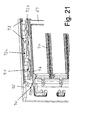
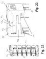
- Figures 21 to 23 show a particular embodiment for the embodiment of Inner sides of the two housing half-shells.
- the inner structure of the housing half shells has a spring channel into which the spring 72 after assembling both Half shells of the housing can be used.
- the spring channel causes a leadership of Spring during insertion, via each laterally extending grooves.
- the grooves for example, by the projections 94 and either the housing top or, as in the illustrated embodiment, via latching tabs 92a, 92b.
- the projection 94 not only forms one side of the spring channel for insertion of the spring, but he also serves as a positioning aid of the elements of the heater. These are (pre) fixed by the projection 94 with play in the housing to a slide-in channel for the spring to be inserted after assembly.
- the embodiment shown in Figures 21 to 23 also has an increased Stiffness up.
- additional stiffening may include among others Reasons are needed.
- Large area heaters i. heaters the narrow but designed with a large area for a high air flow are to achieve high efficiency, very high clamping forces are required. At case temperatures of about 170 degrees Celsius, however, the rigidity of the used plastic after.
- the springs can not force only on the Transmitted edge of the housing, since the spring segments used a distance from a minimum of about 2 mm to 2.5 mm to the edge of the spring. Nevertheless, one To avoid bending of the upper and lower sides of the housing, these are preferably additionally stiffened.
- latching tabs 92a, 92b are opposite in each case half shells arranged latching tabs 92a, 92b provided.
- the latching tabs protrude each in the direction of the opposite half of the housing and are about locking lugs 91 locked together during assembly. Through this gearing on the upper and lower sides of the housing, the mechanical stiffness is increased and prevents sagging.
- a further increase in rigidity can be achieved via an additional side wall 95, 96 be achieved.
- This side wall 95, 96 is respectively above the previous side walls arranged and connected via support members 93 thereto. This way you can the mechanical rigidity of the top and bottom surfaces are increased so that the housing can absorb very high clamping forces.
- This is a "large-scale construction" possible, ie a heater with a plurality of stacked Layers of PTC elements and intermediate radiator elements.
- Fig. 24 is a plan view of the spring element 72
- Fig. 25 is a side view
- Fig. 26 is a perspective view of the spring element 72 reproduced.
- the spring element 72 consists of a sheet metal part 85 and protruding from this Spring segments 86.
- the spring element 72 is integrally formed, wherein the spring segments punched out on three sides of the sheet metal part 85 and are bent about an axis 89 in the transverse direction of the sheet metal part 85.
- the angle ⁇ , um The punched out the segments are bent, is approximately between 5 ° and 30 °, preferably between 15 ° and 20 °.
- the spring interacts ideally with the housing, the can accommodate greater forces only in the housing sides due to its construction and in the middle, in the area of the dividing line, less loadable.
- the side ends of the spring segments arranged very close to the edge of the spring element.
- each spring segment 86 need not be rectangular, but can also have areas include different width and inclination.
- each spring segment have a wider end portion which is slightly flattened, to allow a better insertion of the spring element in the housing.
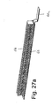
- Fig. 27a is a radiator element 64 and a contact plate 66 connected thereto in an elongated embodiment for a "large surface heating device" (eg according to FIG Fig. 20).
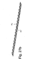
- the corresponding spring element is shown in Fig. 27b.
- the spring element has a plurality of successively arranged spring segments 86 on.
- Each of the spring segments 86 is capable of a pressing force of about 15 N exercise.
- the spring segments of FIG. 27b positioned one behind the other, so that over the surface of a PTC element two or three spring segments 86 are arranged.
- the clamping pressure can be doubled or even tripled.
- the clamping pressure is in contrast to conventional Frame mounts applied evenly over the entire length of the spring.
- the clamping forces generated by the spring segments 86 received by the housing can be, the elongated housing sides are so with cross braces 69 equipped that between two consecutive cross struts 69 two to a maximum of five spring segments 86 are arranged.
- FIG. 15 shows a spring element 72 with two or more side by side arranged spring segments. This embodiment is advantageous in Housing shapes that have a large depth.
- a particular advantage of the heating device according to the invention is that the spring element can be produced for the first time as an endless part and thus from a roll during production can be supplied.
- each spring segment is manufactured separately and individually manufactured for all different heater lengths.
- the heating device takes place as described in connection with FIGS. 12 to 15. According to the assembly of the individual elements takes place in contrast to conventional heaters without the clamping forces on the layered Interacting construction. Only after assembly of the housing, the spring is in the composite Housing inserted (see Fig. 15).
- the invention relates to a new construction principle for electric heaters, where the functions of frame and spring are separated are.
- a housing is used, the consists of two half-shells.
- positioning aids for the PTC heating elements arranged.
- the longitudinal sides of the housing are substantially open designed to allow an air flow through the heater.
- the PTC heaters are painted over attached to a contacting the PTC heating elements contact plate.
- the so prefabricated Modules facilitate assembly and avoid additional positioning means for the correct position of the PTC heating elements during production.
- the paint was also a protection against the ingress of moisture. On This way, an effective corrosion protection is achieved at the same time.
- a spring is incorporated in the housing, which is the layered structure consisting of radiator elements, PTC heating elements and contact plates.
- the Spring can be retrofitted by an opening provided laterally in the housing the housing are inserted. As a result, the housing is only after assembly, if it is mechanically strong, exposed to the spring forces.
- the new construction principle has a number of advantages. On the one hand can with the inventive Construction the weight at the same heat output can be significantly reduced, because no metal frame is used, up to about 50 percent. Furthermore has the heater without additional measures and without additional weight no exposed metal surfaces. Another advantage is the low height that um up to 30 percent below conventional heaters. As a result, too much smaller heaters than conventionally realizable, but still a high Efficiency due to the clamping principle used to increase the electrical and achieve thermal contact. In addition, longer heating elements can be produced, with the conventional holding frame design only with great effort are feasible.
- the construction principle requires no special design of the side rails of a holding frame, to absorb the clamping force acting on the longitudinal beams.
- the narrow sides the housing according to the invention are therefore in their design to any desired Plug geometry customizable, the projecting from the housing connector tongues surrounds the contact sheets.
- the spring is much cheaper to produce in this way.
- the Thickness of the spring can be reduced and thus a material saving can be achieved.
- the spring element can now be produced for the first time as Endlosteil and of be supplied to a role in manufacturing. In addition, a single spring element sufficient.
Landscapes
- Engineering & Computer Science (AREA)
- Mechanical Engineering (AREA)
- Physics & Mathematics (AREA)
- Thermal Sciences (AREA)
- Chemical & Material Sciences (AREA)
- Combustion & Propulsion (AREA)
- General Engineering & Computer Science (AREA)
- Air-Conditioning For Vehicles (AREA)
- Resistance Heating (AREA)
- Surface Heating Bodies (AREA)
- Direct Air Heating By Heater Or Combustion Gas (AREA)
Abstract
Description
- Fig. 1
- eine schematische Darstellung des Aufbringens einer Lackschicht auf einem Kontaktblech,
- Fig. 2
- eine schematische Darstellung des Aufsetzen eines PTC-Heizelementes auf die Lackschicht des Kontaktblechs,
- Fig. 3
- eine schematische Darstellung einer vorfabrizierten Baueinheit aus einem auf einem Kontaktblech fixierten PTC-Heizelement,
- Fig. 4
- eine alternative Ausführungsform einer vorfabrizierten Baueinheit, die in Ergänzung zu den Elementen der Fig. 3 ein Radiatorelement umfasst,
- Fig. 5
- eine schematische Darstellung eines Ausschnitts einer erfindungsgemäßen Heizvorrichtung mit einer in diese eingesetzte, vorfabrizierte Baueinheit gemäß Fig. 4,
- Fig. 6
- eine schematische Ansicht eines inneren Aufbaus einer erfindungsgemäßen Heizvorrichtung,
- Fig. 7a
- ein schematische Schnittansicht durch eine erfindungsgemäße Baueinheit aus einem Radiatorelement, einem über eine Lackschicht versiegelten Kontaktblech und ein auf dem Kontaktblech angeordneten PTC-Heizelement,
- Fig. 7b
- eine perspektivische Ansicht einer Baueinheit gemäß Fig. 7a,
- Fig. 8
- eine schematische Schnittansicht durch eine erfindungsgemäße Heizvorrichtung mit einem Kunststoffgehäuse und in diesem in mehreren Schichten angeordneten PTC-Heizelementen, Kontaktblechen und Radiatorelementen,
- Fig. 9
- eine aufgeschnittene, perspektivische Ansicht einer erfindungsgemäßen elektrischen Heizvorrichtung gemäß Fig. 8, wobei jedoch nur eine Halbschale des Gehäuses dargestellt ist,
- Fig. 10
- eine Aufsicht auf die erfindungsgemäße Heizvorrichtung gemäß Fig. 9 mit den in einer Halbschale angeordneten Radiatorelementen, Kontaktblechen und PTC-Heizelementen,
- Fig. 11
- eine Ansicht eines geschichteten Aufbaus aus Radiatorelementen, Kontaktblechen und PTC-Heizelementen, wie er im Gehäuse einer erfindungsgemäßen elektrischen Heizvorrichtung angeordnet ist,
- Fig. 12
- eine perspektivische Ansicht einer Halbschale des Gehäuses der elektrischen Heizvorrichtung der Erfindung, die nur zum Teil bestückt ist,
- Fig. 13
- eine perspektivische Ansicht einer Halbschale des Gehäuses der elektrischen Heizvorrichtung gemäß Fig. 12, die vollständig bestückt ist,
- Fig. 14
- eine perspektivische Ansicht des zusammengesetzten Gehäuses der elektrischen Heizvorrichtung,
- Fig. 15
- eine perspektivische Ansicht der elektrischen Heizvorrichtung gemäß Fig. 14, bei der das Federelement teilweise eingeschoben ist,
- Fig. 16
- eine perspektivische Ansicht einer anderen Ausführungsform des Gehäuses der erfindungsgemäßen Heizvorrichtung,
- Fig. 17
- eine weitere perspektivische Ansicht der Ausführungsform nach Fig. 16, bei der die Gehäuseseite, an der die Kontaktstifte vorgesehen sind, beispielhaft an eine spezielle Steckergeometrie angepasst ist,
- Fig. 18
- eine weitere Detailansicht der Ausführungsform des Gehäuses der erfindungsgemäßen Heizvorrichtung nach Fig. 16,
- Fig. 19
- eine perspektivische Ansicht einer schematischen Darstellung einer weiteren Ausführungsform der erfindungsgemäßen Heizvorrichtung während des Zusammenbaus,
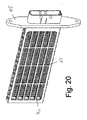
- Fig. 20
- eine perspektivische Ansicht der zusammengesetzten Ausführungsform nach Fig. 19,
- Fig. 21
- eine Detailansicht der Innenseite einer Gehäusehalbschale einer weiteren Ausführungsform der Erfindung,
- Fig. 22
- eine Schnittansicht durch die zusammengesetzten Halbschalen des Gehäuses der Ausführungsform nach Fig. 21,
- Fig. 23
- eine vergrößerte Ansicht eines Details der Gehäusedarstellung aus Fig. 22, bei dem die Einzelheiten des verschränkten Aufbaus der Gehäuseseiten für eine stärkere mechanische Belastbarkeit der Gehäuselängsseiten deutlich erkennbar ist,
- Fig. 24
- eine schematische Darstellungen einer Aufsicht auf das erfindungsgemäße Federelement,
- Fig. 25
- eine schematische Darstellungen einer Seitenansicht auf das erfindungsgemäße Federelement,
- Fig. 26
- eine schematische Darstellungen einer perspektivischen Ansicht des erfin- dungsgemäßen Federelementes,
- Fig. 27a
- eine Ansicht eines Wellrippenelements mit einem an diesem befestigten Kontaktblech und
- Fig. 27b
- eine Ansicht einer weiteren Ausgestaltung des Federelementes.
Claims (41)
- Elektrische Heizvorrichtung, insbesondere als Zusatzheizung für Kraftfahrzeuge, mit einem Gehäuse (62), das an den länglichen Gehäusestimseiten offen ausgebildet ist, und einem geschichteten Aufbau aus wenigstens einem PTC-Heizelement (4), einem Radiatorelement (5), einem ersten und einem zweiten Kontaktblech (2,10) zur Stromzuführung, wobei das PTC-Heizelement (4) zwischen dem ersten und dem zweiten Kontaktblech (2, 10) angeordnet ist, und einem Federelement (72), wobei der geschichtete Aufbau durch das Federelement (72) in dem Gehäuse (62) geklemmt gehalten ist,
dadurch gekennzeichnet, dass
das erste Kontaktblech (2) auf der dem PTC-Heizelement (4) zugewandten Seite mit einer Lackschicht (3) versehen ist und der Zwischenraum zwischen dem PTC-Heizelement (4) und dem ersten Kontaktblech (2) über aus diesem Zwischenraum herausgepressten Lack (12) abgedichtet ist. - Elektrische Heizvorrichtung nach Anspruch 1, dadurch gekennzeichnet, dass der Lack ein elektrisch nicht-leitender Silikonlack (3) ist.
- Elektrische Heizvorrichtung nach Anspruch 1 oder 2, dadurch gekennzeichnet, dass der Lack (3) eine Viskosität niedriger als 900 mPa.s, vorzugsweise von etwa 800 mPa.s aufweist.
- Elektrische Heizvorrichtung nach einem der Ansprüche 1 bis 3, dadurch gekennzeichnet, dass das erste Kontaktblech (2) aus Aluminium hergestellt ist.
- Elektrische Heizvorrichtung nach einem der Ansprüche 1 bis 4, dadurch gekennzeichnet, dass das zweite Kontaktblech (10) aus Messing hergestellt ist.
- Elektrische Heizvorrichtung nach einem der Ansprüche 1 bis 5, dadurch gekennzeichnet, dass das zweite Kontaktblech (10) verzinnt ist.
- Elektrische Heizvorrichtung nach einem der Ansprüche 1 bis 5, gekennzeichnet durch eine seitlich in dem Gehäuse (62) vorgesehene Öffnung (71) zum Einschieben des Federelementes (72).
- Elektrische Heizvorrichtung nach einem der Ansprüche 1 bis 7, gekennzeichnet durch einen in dem Gehäuse (62) ausgebildeten Federkanal zur Aufnahme des Federelementes (72).
- Elektrische Heizvorrichtung nach einem der Ansprüche 1 bis 8, gekennzeichnet durch Positionierungsmittel (94) zum Vorfixieren der Elemente der Heizvorrichtung in dem Gehäuse (62).
- Elektrische Heizvorrichtung nach Anspruch 9, dadurch gekennzeichnet, dass die Positionierungsmittel (94) in dem Gehäuse (62) gleichzeitig eine Nut zur Führung des Federelementes (72) beim Einschieben bilden.
- Elektrische Heizvorrichtung nach einem der Ansprüche 1 bis 10, dadurch gekennzeichnet, dass die länglichen Gehäusestimseiten durch wenigstens eine Querverstrebung (69) mechanisch verstärkt sind.
- Elektrische Heizvorrichtung nach Anspruch 11, dadurch gekennzeichnet, dass die Verstrebungen (69,70) in den länglichen Gehäusestimseiten die Form einer Gitterstruktur aufweisen.
- Elektrische Heizvorrichtung nach Anspruch 11 oder 12, dadurch gekennzeichnet, dass die Gitterstruktur wenigstens eine Längsverstrebung (70) im Bereich der PTC-Heizelemente (4) aufweist.
- Elektrische Heizvorrichtung nach einem der Ansprüche 1 bis 13, dadurch gekennzeichnet, dass das Gehäuse (62) aus Kunststoff hergestellt ist.
- Elektrische Heizvorrichtung nach einem der Ansprüche 1 bis 11, dadurch gekennzeichnet, dass das Gehäuse (62) zwei Halbschalen (62a,62b) umfaßt.
- Elektrische Heizvorrichtung nach Anspruch 15, dadurch gekennzeichnet, dass die Halbschalen (62a,62b) des Gehäuses (62) zusammensteckbar sind.
- Elektrische Heizvorrichtung nach Anspruch 16, gekennzeichnet durch Rastzapfen (78) oder Rastnasen (91), die beim Zusammenstecken der Halbschalen (62a,62b) des Gehäuses (62) ein Verrasten beider Halbschalen (62a,62b) bewirken.
- Elektrische Heizvorrichtung nach einem der Ansprüche 16 bis 17, dadurch gekennzeichnet, dass die Halbschalen (62a,62b) so ausgebildet sind, dass sie das Gehäuse (62) in etwa mittig zwischen den länglichen Gehäusestimseiten trennen.
- Elektrische Heizvorrichtung nach Anspruch 18, gekennzeichnet durch jeweils gegenüberliegende Vorsprünge (76, 77; 92a, 92b) an der Trennlinie der Halbschalen (62a,62b), die beim Zusammensetzen der Halbschalen (62a,62b) ineinander greifen.
- Elektrische Heizvorrichtung nach einem der Ansprüche 1 bis 19, dadurch gekennzeichnet, dass das Federelement (72) so ausgebildet ist, dass es die Klemmkräfte im wesentlichen auf die verstärkt ausgebildeten Gehäuselängsseiten überträgt.
- Elektrische Heizvorrichtung nach einem der Ansprüche 1 bis 20, dadurch gekennzeichnet, dass das Federelement (72) aus einem Blechteil (85) mit aus diesem herausragenden Federsegmenten (86) besteht.
- Elektrische Heizvorrichtung nach Anspruch 21, dadurch gekennzeichnet, dass die Federsegmente (86) jeweils bis in die Randbereiche der Längsseiten des Federelementes (72) reichen.
- Elektrische Heizvorrichtung nach Anspruch 22, dadurch gekennzeichnet, dass das Federelement (72) mit den Federsegmenten (86) einstückig ausgebildet ist.
- Elektrische Heizvorrichtung nach einem der Ansprüche 1 bis 23, dadurch gekennzeichnet, dass wenigstens ein Federsegment (86) zur Erzeugung von Klemmkräften an jeder PTC-Heizelement-Postion für eine kraftschlüssige Klemmung vorgesehen ist.
- Elektrische Heizvorrichtung nach Anspruch 24, dadurch gekennzeichnet, dass für jede PTC-Heizelement-Position wenigstens zwei Federsegmente (86) vorgesehen sind.
- Baueinheit für eine elektrische Heizvorrichtung, insbesondere als Zusatzheizung für Kraftfahrzeuge, wobei die elektrische Heizvorrichtung ein Gehäuse (62), das an den länglichen Gehäusestimseiten offen ausgebildet ist, und einen geschichteten Aufbau aus wenigstens einem PTC-Heizelement (4), einem Radiatorelement (4), einem ersten und einem zweiten Kontaktblech (2,10) zur Stromzuführung, wobei das PTC-Heizelement (4) zwischen dem ersten und dem zweiten Kontaktblech (2, 10) angeordnet ist, und einem Federelement (72) umfasst, wobei der geschichtete Aufbau durch das Federelement (72) in dem Gehäuse (62) geklemmt gehalten ist,
dadurch gekennzeichnet, dass
die Baueinheit aus dem ersten Kontaktblech (66) und einem PTC-Heizelement (4) gebildet ist, wobei das erste Kontaktblech (66) auf der dem PTC-Heizelement (4) zugewandten Seite mit einer Lackschicht (3) versehen ist und der Zwischenraum zwischen dem PTC-Heizelement (4) und dem ersten Kontaktblech (2) über aus dem Zwischenraum herausgepressten Lack (12) abgedichtet ist. - Baueinheit nach Anspruch 26, dadurch gekennzeichnet, dass der Lack ein elektrisch nicht-leitender Silikonlack (3) ist.
- Baueinheit nach Anspruch 26 oder 27, dadurch gekennzeichnet, dass der Lack (3) eine Viskosität niedriger als 900 mPa.s, vorzugsweise von etwa 800 mPa.s aufweist.
- Baueinheit nach einem der Ansprüche 26 bis 28, dadurch gekennzeichnet, dass das erste Kontaktblech (2) aus Aluminium hergestellt ist.
- Baueinheit nach einem der Ansprüche 26 bis 29, dadurch gekennzeichnet, dass das zweite Kontaktblech (10) aus Messing hergestellt ist.
- Baueinheit nach einem der Ansprüche 29 bis 33, dadurch gekennzeichnet, dass das zweite Kontaktblech (10) verzinnt ist.
- Verfahren zur Herstellung einer elektrischen Heizvorrichtung (20), insbesondere als Zusatzheizung für Kraftfahrzeuge, mit einem Gehäuse (62) aus zwei Halbschalen (62a,62b), das an den länglichen Gehäusestimseiten offen ausgebildet ist, und einem geschichteten Aufbau aus wenigstens einem PTC-Heizelement (4), einem Radiatorelement (5), einem ersten und einem zweiten Kontaktblech (2,10) zur Stromzuführung und einem Federelement (72), wobei der geschichtete Aufbau durch das Federelement (42) in dem Gehäuse (62) geklemmt gehalten ist, mit den Montageschritten:Befestigen eines PTC-Heizelementes (4) auf dem ersten Kontaktblech (2) mittels eines Lacks (3),Einsetzen des ersten Kontaktblechs (2) mit dem auf diesem befestigten PTC-Heizelement (4) und des zweiten Kontaktblechen (2,10) in eine erste Halbschale (62a) des Gehäuses undAufstecken der zweiten Halbschale (62b) des Gehäuses (62) auf die erste Halbschale (62a).
- Verfahren nach Anspruch 32, dadurch gekennzeichnet, dass der Lack (3) ein elektrisch nicht-leitender Silikonlack ist.
- Verfahren nach Anspruch 32 oder 33, dadurch gekennzeichnet, dass der Lack (3) eine Viskosität größer als 900 mPa.s, vorzugsweise von etwa 800 mPa.s aufweist.
- Verfahren nach einem der Ansprüche 32 bis 34, dadurch gekennzeichnet, dass die Befestigung des PTC-Heizelementes (4) über den Lack (3) nur geringen mechanischen Belastungen standhält.
- Verfahren nach einem der Ansprüche 32 bis 35, dadurch gekennzeichnet, dass das Federelement (72) durch eine Öffnung (71) des zusammengesetzten Gehäuses (62) eingeschoben wird, um eine Klemmung des geschichteten Aufbaus zu bewirken.
- Verfahren nach einem der Ansprüche 32 bis 36, dadurch gekennzeichnet, dass mit dem Einsetzen des Federelementes (72) der Lack (3) aus dem Bereich zwischen den PTC-Heizelementen (4) und dem Kontaktblech (2) über den durch das Federelement (72) erzeugten Anpressdruck herausgedrückt wird.
- Verfahren nach einem der Ansprüche 32 bis 38, dadurch gekennzeichnet, dass der aus dem Bereich zwischen dem PTC-Heizelement (4) und dem Kontaktblech (2,10) herausgepresste Lack (12) diesen Bereich gegen eindringende Feuchtigkeit abdichtet.
- Verfahren nach einem der Ansprüche 32 bis 38, dadurch gekennzeichnet, dass das erste Kontaktblech (2) aus Aluminium hergestellt ist.
- Verfahren nach einem der Ansprüche 32 bis 39, dadurch gekennzeichnet, dass das zweite Kontaktblech (10) aus Messing hergestellt ist.
- Verfahren nach einem der Ansprüche 32 bis 40, dadurch gekennzeichnet, dass das zweite Kontaktblech (10) verzinnt ist.
Priority Applications (7)
| Application Number | Priority Date | Filing Date | Title |
|---|---|---|---|
| EP03020700A EP1515587B1 (de) | 2003-09-11 | 2003-09-11 | Elektrische Heizvorrichtung mit versiegeltem Heizelement |
| DE50305966T DE50305966D1 (de) | 2003-09-11 | 2003-09-11 | Elektrische Heizvorrichtung mit versiegeltem Heizelement |
| ES03020700T ES2275988T3 (es) | 2003-09-11 | 2003-09-11 | Dispositivo calefactor electrico, con elemento calefactor sellado. |
| CNB2004100064599A CN100348433C (zh) | 2003-09-11 | 2004-03-08 | 带有护盖的电加热装置 |
| JP2004093423A JP3929988B2 (ja) | 2003-09-11 | 2004-03-26 | ハウジングを備えた電気加熱装置 |
| KR1020040029266A KR100730416B1 (ko) | 2003-09-11 | 2004-04-27 | 하우징을 갖는 전기 가열 장치 |
| US10/835,895 US7012225B2 (en) | 2003-09-11 | 2004-04-30 | Electric heating apparatus with housing |
Applications Claiming Priority (1)
| Application Number | Priority Date | Filing Date | Title |
|---|---|---|---|
| EP03020700A EP1515587B1 (de) | 2003-09-11 | 2003-09-11 | Elektrische Heizvorrichtung mit versiegeltem Heizelement |
Publications (2)
| Publication Number | Publication Date |
|---|---|
| EP1515587A1 true EP1515587A1 (de) | 2005-03-16 |
| EP1515587B1 EP1515587B1 (de) | 2006-12-13 |
Family
ID=34130193
Family Applications (1)
| Application Number | Title | Priority Date | Filing Date |
|---|---|---|---|
| EP03020700A Expired - Lifetime EP1515587B1 (de) | 2003-09-11 | 2003-09-11 | Elektrische Heizvorrichtung mit versiegeltem Heizelement |
Country Status (7)
| Country | Link |
|---|---|
| US (1) | US7012225B2 (de) |
| EP (1) | EP1515587B1 (de) |
| JP (1) | JP3929988B2 (de) |
| KR (1) | KR100730416B1 (de) |
| CN (1) | CN100348433C (de) |
| DE (1) | DE50305966D1 (de) |
| ES (1) | ES2275988T3 (de) |
Cited By (7)
| Publication number | Priority date | Publication date | Assignee | Title |
|---|---|---|---|---|
| EP2023056A1 (de) | 2007-07-30 | 2009-02-11 | Chia-Hsiung Wu | Bindungsverfahren für einen Lufterhitzer und dessen Struktur |
| EP2083607A1 (de) * | 2008-01-23 | 2009-07-29 | Behr France Rouffach SAS | Vorrichtung zum Heizen insbesondere eines Kraftfahrzeuges |
| EP2337425A1 (de) * | 2009-12-17 | 2011-06-22 | Eberspächer catem GmbH & Co. KG | Elektrische Heizvorrichtung und wärmeerzeugendes Element einer elektrischen Heizvorrichtung |
| EP2806707A1 (de) * | 2013-05-21 | 2014-11-26 | Behr France Rouffach SAS | Heizkörper |
| WO2021155997A1 (de) * | 2020-02-05 | 2021-08-12 | CIRCINO Innovation UG | Elektrische heizvorrichtung und verfahren zum herstellen einer heizvorrichtung |
| DE102022120453A1 (de) | 2022-08-12 | 2024-02-15 | Eberspächer Catem Gmbh & Co. Kg | PTC-Heizvorrichtung und Verfahren zu deren Herstellung |
| DE102024131736A1 (de) | 2024-10-30 | 2026-04-30 | Eberspächer Catem Gmbh & Co. Kg | Elektrische Heizeinrichtung und Verfahren zu deren Herstellung |
Families Citing this family (25)
| Publication number | Priority date | Publication date | Assignee | Title |
|---|---|---|---|---|
| ATE357123T1 (de) * | 2004-11-11 | 2007-04-15 | Dbk David & Baader Gmbh | Elektrischer platinenheizbaustein, elektronikplatine und verfahren zum beheizen |
| ES2303712T3 (es) * | 2005-09-23 | 2008-08-16 | CATEM GMBH & CO. KG | Elemento generador de calor para un dispositivo de calefaccion. |
| EP1768457B1 (de) * | 2005-09-23 | 2008-05-14 | Catem GmbH & Co.KG | Wärmeerzeugendes Element einer Heizvorrichtung |
| KR100811293B1 (ko) * | 2006-05-17 | 2008-03-07 | 우리산업 주식회사 | 커버 결합형 차량용 프리히터 |
| US7576305B2 (en) * | 2006-09-22 | 2009-08-18 | Catem Gmbh & Co. Kg | Heat-generating element of a heating device |
| US8232509B2 (en) * | 2006-11-16 | 2012-07-31 | S.C. Johnson & Son, Inc. | Retainer system |
| US7288748B1 (en) | 2006-12-21 | 2007-10-30 | S.C. Johnson & Son, Inc. | PTC electrical heating devices |
| EP2017546B1 (de) * | 2007-07-18 | 2016-04-13 | Eberspächer catem GmbH & Co. KG | Verfahren zum Herstellen einer elektrischen Heizvorrichtung sowie elektrischer Heizvorrichtungen |
| EP2017545B1 (de) * | 2007-07-18 | 2012-04-25 | Eberspächer catem GmbH & Co. KG | Elektrische Heizvorrichtung |
| DE502007005351D1 (de) * | 2007-07-20 | 2010-11-25 | Eberspaecher Catem Gmbh & Co K | Elektrische Heizvorrichtung insbesondere für Kraftfahrzeuge |
| US20090139972A1 (en) * | 2007-10-23 | 2009-06-04 | Psion Teklogix Inc. | Docking connector |
| US8027575B2 (en) * | 2008-01-31 | 2011-09-27 | S.C. Johnson & Son, Inc. | Heater contact assembly for volatile liquid dispenser |
| DE102008033140A1 (de) * | 2008-07-15 | 2010-01-21 | Beru Ag | Fahrzeugheizung |
| DE102008033142A1 (de) * | 2008-07-15 | 2010-01-21 | Eichenauer Heizelemente Gmbh & Co. Kg | Fahrzeugheizung |
| EP2190258A1 (de) | 2008-11-20 | 2010-05-26 | Behr France Rouffach SAS | Wärmeübertrager |
| DE102009033705A1 (de) * | 2008-12-01 | 2010-06-02 | W.E.T. Automotive Systems Ag | Elektrische Heizvorrichtung |
| KR101014494B1 (ko) * | 2008-12-05 | 2011-02-14 | 현대자동차주식회사 | 피티씨 히터 |
| KR101199128B1 (ko) * | 2010-11-05 | 2012-11-09 | 임은섭 | 히터 어셈블리 |
| DE102012109801B4 (de) * | 2012-10-15 | 2015-02-05 | Borgwarner Ludwigsburg Gmbh | Elektrische Heizvorrichtung |
| USD757917S1 (en) * | 2013-11-27 | 2016-05-31 | Jahwa Electronics Co., Ltd. | Electric heater mounted on air conditioner for vehicle |
| EP3045836B8 (de) * | 2015-01-15 | 2019-07-10 | Stylianos Giannoulis | Heizvorrichtung |
| JP6513522B2 (ja) * | 2015-07-22 | 2019-05-15 | 株式会社日本クライメイトシステムズ | 電気式ヒータ |
| JP7157607B2 (ja) * | 2018-09-26 | 2022-10-20 | 三菱重工サーマルシステムズ株式会社 | 熱媒体加熱装置及び車両用空調装置 |
| DE102018220858A1 (de) * | 2018-12-03 | 2020-06-04 | Eberspächer Catem Gmbh & Co. Kg | Elektrische Heizvorrichtung |
| FR3089745A1 (fr) * | 2018-12-10 | 2020-06-12 | Valeo Systemes Thermiques | Procédé d’assemblage d’un module chauffant pour dispositif de chauffage électrique et dispositif de chauffage électrique associé |
Citations (2)
| Publication number | Priority date | Publication date | Assignee | Title |
|---|---|---|---|---|
| EP1182908A1 (de) * | 2000-08-25 | 2002-02-27 | Catem GmbH & Co.KG | PTC-Heizvorrichtung mit Klebestoff |
| DE10121568A1 (de) | 2001-04-25 | 2002-10-31 | Behr France Sarl | Elektrische Heizeinrichtung mit in einem Rahmen gehaltenem Heizblock |
Family Cites Families (11)
| Publication number | Priority date | Publication date | Assignee | Title |
|---|---|---|---|---|
| DE4014310A1 (de) * | 1990-05-04 | 1991-11-07 | Bayer Ag | Siliconelastomere mit vermindertem druckverformungsrest sowie verfahren zu deren herstellung |
| US5256857A (en) * | 1990-08-22 | 1993-10-26 | Texas Instruments Incorporated | Finned PTC air heater assembly for heating an automotive passenger compartment |
| JPH0521134A (ja) * | 1991-07-02 | 1993-01-29 | Sumitomo Metal Ind Ltd | Ptcサーミスタ発熱体 |
| US5326418A (en) | 1992-04-14 | 1994-07-05 | Yeh Yuan Chang | Method of making positive-temperature-coefficient thermistor heating element |
| US5471034A (en) * | 1993-03-17 | 1995-11-28 | Texas Instruments Incorporated | Heater apparatus and process for heating a fluid stream with PTC heating elements electrically connected in series |
| KR200156191Y1 (ko) | 1994-07-09 | 1999-09-01 | 로빈예 | 정의 온도계수 서미스터 가열 어셈블리 |
| JPH08148262A (ja) * | 1994-11-18 | 1996-06-07 | Matsushita Electric Ind Co Ltd | 正特性サーミスタ発熱体 |
| WO1997006537A2 (en) * | 1995-08-07 | 1997-02-20 | Philips Electronics N.V. | Multiplet ptc resistor |
| JP3191655B2 (ja) * | 1996-01-26 | 2001-07-23 | 松下電器産業株式会社 | 正特性サーミスタ発熱体 |
| US6178292B1 (en) * | 1997-02-06 | 2001-01-23 | Denso Corporation | Core unit of heat exchanger having electric heater |
| ATE458378T1 (de) * | 2001-12-06 | 2010-03-15 | Eberspaecher Catem Gmbh & Co K | Elektrische heizvorrichtung |
-
2003
- 2003-09-11 EP EP03020700A patent/EP1515587B1/de not_active Expired - Lifetime
- 2003-09-11 DE DE50305966T patent/DE50305966D1/de not_active Expired - Lifetime
- 2003-09-11 ES ES03020700T patent/ES2275988T3/es not_active Expired - Lifetime
-
2004
- 2004-03-08 CN CNB2004100064599A patent/CN100348433C/zh not_active Expired - Lifetime
- 2004-03-26 JP JP2004093423A patent/JP3929988B2/ja not_active Expired - Fee Related
- 2004-04-27 KR KR1020040029266A patent/KR100730416B1/ko not_active Expired - Lifetime
- 2004-04-30 US US10/835,895 patent/US7012225B2/en not_active Expired - Lifetime
Patent Citations (2)
| Publication number | Priority date | Publication date | Assignee | Title |
|---|---|---|---|---|
| EP1182908A1 (de) * | 2000-08-25 | 2002-02-27 | Catem GmbH & Co.KG | PTC-Heizvorrichtung mit Klebestoff |
| DE10121568A1 (de) | 2001-04-25 | 2002-10-31 | Behr France Sarl | Elektrische Heizeinrichtung mit in einem Rahmen gehaltenem Heizblock |
Cited By (9)
| Publication number | Priority date | Publication date | Assignee | Title |
|---|---|---|---|---|
| EP2023056A1 (de) | 2007-07-30 | 2009-02-11 | Chia-Hsiung Wu | Bindungsverfahren für einen Lufterhitzer und dessen Struktur |
| EP2083607A1 (de) * | 2008-01-23 | 2009-07-29 | Behr France Rouffach SAS | Vorrichtung zum Heizen insbesondere eines Kraftfahrzeuges |
| EP2337425A1 (de) * | 2009-12-17 | 2011-06-22 | Eberspächer catem GmbH & Co. KG | Elektrische Heizvorrichtung und wärmeerzeugendes Element einer elektrischen Heizvorrichtung |
| US8637796B2 (en) | 2009-12-17 | 2014-01-28 | Eberspacher Catem GmbH & KG | Electrical heating device and heat generating element of an electrical heating device |
| EP2806707A1 (de) * | 2013-05-21 | 2014-11-26 | Behr France Rouffach SAS | Heizkörper |
| EP2806708A1 (de) * | 2013-05-21 | 2014-11-26 | Behr France Rouffach SAS | Heizkörper |
| WO2021155997A1 (de) * | 2020-02-05 | 2021-08-12 | CIRCINO Innovation UG | Elektrische heizvorrichtung und verfahren zum herstellen einer heizvorrichtung |
| DE102022120453A1 (de) | 2022-08-12 | 2024-02-15 | Eberspächer Catem Gmbh & Co. Kg | PTC-Heizvorrichtung und Verfahren zu deren Herstellung |
| DE102024131736A1 (de) | 2024-10-30 | 2026-04-30 | Eberspächer Catem Gmbh & Co. Kg | Elektrische Heizeinrichtung und Verfahren zu deren Herstellung |
Also Published As
| Publication number | Publication date |
|---|---|
| ES2275988T3 (es) | 2007-06-16 |
| EP1515587B1 (de) | 2006-12-13 |
| JP3929988B2 (ja) | 2007-06-13 |
| JP2005093415A (ja) | 2005-04-07 |
| US7012225B2 (en) | 2006-03-14 |
| KR100730416B1 (ko) | 2007-06-19 |
| KR20050026980A (ko) | 2005-03-17 |
| CN100348433C (zh) | 2007-11-14 |
| US20050056637A1 (en) | 2005-03-17 |
| CN1593964A (zh) | 2005-03-16 |
| DE50305966D1 (de) | 2007-01-25 |
Similar Documents
| Publication | Publication Date | Title |
|---|---|---|
| EP1515587B1 (de) | Elektrische Heizvorrichtung mit versiegeltem Heizelement | |
| EP1432287B1 (de) | Elektrische Heizvorrichtung mit Gehäuse | |
| EP1061776B1 (de) | Heizvorrichtung zur Lufterwärmung | |
| EP1564503B1 (de) | Elektrische Heizvorrichtung für niedrige Bauhöhen | |
| EP1790916B1 (de) | Elektrische Heizvorrichtung mit Toleranz-PTC-Heizelement | |
| EP0705055B1 (de) | Elektrische Heizeinrichtung, insbesondere für ein Kraftfahrzeug | |
| EP1931176B1 (de) | Eine elektrische Heizvorrichtung und Verfahren zur Herstellung derselben | |
| EP1327834B1 (de) | Radiatorelement für eine Heizvorrichtung | |
| DE102016125476B4 (de) | Batterieträger für ein Elektrokraftfahrzeug mit Kühlsystem | |
| EP1852878B2 (de) | Leistungswiderstandsmodul | |
| EP2337425A1 (de) | Elektrische Heizvorrichtung und wärmeerzeugendes Element einer elektrischen Heizvorrichtung | |
| EP2017548A1 (de) | Elektrische Heizvorrichtung insbesondere für Kraftfahrzeuge | |
| DE102009058809A1 (de) | Kühlvorrichtung für eine Fahrzeugantriebsbatterie und Fahrzeugantriebsbatteriebaugruppe mit Kühlvorrichtung | |
| EP1552733B1 (de) | Verfahren zur montage eines schaltungsmoduls | |
| DE3119302A1 (de) | Luftheizvorrichtung | |
| EP4064788B1 (de) | Elektrische heizvorrichtung | |
| WO2011012209A1 (de) | Einzelzelle für eine batterie | |
| DE102006018151B4 (de) | Heizgerät | |
| EP1851845A1 (de) | Elektromotor mit einem aus mehreren blechpaketen gebildeten segmentierten teil und verfahren zum zusammenfügen der blechpakete | |
| DE102020113402A1 (de) | Elektrische Heizvorrichtung | |
| DE102020208643A1 (de) | Heizzelle und PTC-Heizeinrichtung umfassend eine solche | |
| EP4084577B1 (de) | Elektrische heizvorrichtung und verfahren zu deren herstellung | |
| DE102018216047A1 (de) | Kühlstruktur | |
| EP1457368B1 (de) | Heizkörper mit integrierter elektrischer Zusatzheizung | |
| EP1253032B1 (de) | Elektrische Heizeinrichtung mit in einem Rahmen gehaltenen Heizblock |
Legal Events
| Date | Code | Title | Description |
|---|---|---|---|
| PUAI | Public reference made under article 153(3) epc to a published international application that has entered the european phase |
Free format text: ORIGINAL CODE: 0009012 |
|
| 17P | Request for examination filed |
Effective date: 20040223 |
|
| AK | Designated contracting states |
Kind code of ref document: A1 Designated state(s): AT BE BG CH CY CZ DE DK EE ES FI FR GB GR HU IE IT LI LU MC NL PT RO SE SI SK TR |
|
| AX | Request for extension of the european patent |
Extension state: AL LT LV MK |
|
| GRAP | Despatch of communication of intention to grant a patent |
Free format text: ORIGINAL CODE: EPIDOSNIGR1 |
|
| GRAS | Grant fee paid |
Free format text: ORIGINAL CODE: EPIDOSNIGR3 |
|
| AKX | Designation fees paid |
Designated state(s): DE ES FR GB IT |
|
| GRAA | (expected) grant |
Free format text: ORIGINAL CODE: 0009210 |
|
| AK | Designated contracting states |
Kind code of ref document: B1 Designated state(s): DE ES FR GB IT |
|
| REG | Reference to a national code |
Ref country code: GB Ref legal event code: FG4D Free format text: NOT ENGLISH |
|
| GBT | Gb: translation of ep patent filed (gb section 77(6)(a)/1977) |
Effective date: 20061213 |
|
| REF | Corresponds to: |
Ref document number: 50305966 Country of ref document: DE Date of ref document: 20070125 Kind code of ref document: P |
|
| REG | Reference to a national code |
Ref country code: ES Ref legal event code: FG2A Ref document number: 2275988 Country of ref document: ES Kind code of ref document: T3 |
|
| ET | Fr: translation filed | ||
| PLBE | No opposition filed within time limit |
Free format text: ORIGINAL CODE: 0009261 |
|
| STAA | Information on the status of an ep patent application or granted ep patent |
Free format text: STATUS: NO OPPOSITION FILED WITHIN TIME LIMIT |
|
| 26N | No opposition filed |
Effective date: 20070914 |
|
| PGFP | Annual fee paid to national office [announced via postgrant information from national office to epo] |
Ref country code: ES Payment date: 20110926 Year of fee payment: 9 Ref country code: GB Payment date: 20110920 Year of fee payment: 9 |
|
| GBPC | Gb: european patent ceased through non-payment of renewal fee |
Effective date: 20120911 |
|
| PG25 | Lapsed in a contracting state [announced via postgrant information from national office to epo] |
Ref country code: GB Free format text: LAPSE BECAUSE OF NON-PAYMENT OF DUE FEES Effective date: 20120911 |
|
| REG | Reference to a national code |
Ref country code: ES Ref legal event code: FD2A Effective date: 20131021 |
|
| PG25 | Lapsed in a contracting state [announced via postgrant information from national office to epo] |
Ref country code: ES Free format text: LAPSE BECAUSE OF NON-PAYMENT OF DUE FEES Effective date: 20120912 |
|
| REG | Reference to a national code |
Ref country code: FR Ref legal event code: PLFP Year of fee payment: 14 |
|
| REG | Reference to a national code |
Ref country code: FR Ref legal event code: PLFP Year of fee payment: 15 |
|
| REG | Reference to a national code |
Ref country code: FR Ref legal event code: PLFP Year of fee payment: 16 |
|
| PGFP | Annual fee paid to national office [announced via postgrant information from national office to epo] |
Ref country code: DE Payment date: 20220920 Year of fee payment: 20 |
|
| PGFP | Annual fee paid to national office [announced via postgrant information from national office to epo] |
Ref country code: FR Payment date: 20220921 Year of fee payment: 20 |
|
| PGFP | Annual fee paid to national office [announced via postgrant information from national office to epo] |
Ref country code: IT Payment date: 20220930 Year of fee payment: 20 |
|
| REG | Reference to a national code |
Ref country code: DE Ref legal event code: R071 Ref document number: 50305966 Country of ref document: DE |