EP1515468A1 - Ofdm-empfangsvorrichtung und ofdm-signalkorrekturverfahren - Google Patents
Ofdm-empfangsvorrichtung und ofdm-signalkorrekturverfahren Download PDFInfo
- Publication number
- EP1515468A1 EP1515468A1 EP03733476A EP03733476A EP1515468A1 EP 1515468 A1 EP1515468 A1 EP 1515468A1 EP 03733476 A EP03733476 A EP 03733476A EP 03733476 A EP03733476 A EP 03733476A EP 1515468 A1 EP1515468 A1 EP 1515468A1
- Authority
- EP
- European Patent Office
- Prior art keywords
- signal
- fourier transform
- section
- sampling signal
- transform processing
- Prior art date
- Legal status (The legal status is an assumption and is not a legal conclusion. Google has not performed a legal analysis and makes no representation as to the accuracy of the status listed.)
- Withdrawn
Links
Images


Classifications
-
- H—ELECTRICITY
- H04—ELECTRIC COMMUNICATION TECHNIQUE
- H04L—TRANSMISSION OF DIGITAL INFORMATION, e.g. TELEGRAPHIC COMMUNICATION
- H04L27/00—Modulated-carrier systems
- H04L27/26—Systems using multi-frequency codes
- H04L27/2601—Multicarrier modulation systems
- H04L27/2614—Peak power aspects
-
- H—ELECTRICITY
- H04—ELECTRIC COMMUNICATION TECHNIQUE
- H04L—TRANSMISSION OF DIGITAL INFORMATION, e.g. TELEGRAPHIC COMMUNICATION
- H04L27/00—Modulated-carrier systems
- H04L27/26—Systems using multi-frequency codes
- H04L27/2601—Multicarrier modulation systems
- H04L27/2647—Arrangements specific to the receiver only
- H04L27/2649—Demodulators
- H04L27/26524—Fast Fourier transform [FFT] or discrete Fourier transform [DFT] demodulators in combination with other circuits for demodulation
- H04L27/26526—Fast Fourier transform [FFT] or discrete Fourier transform [DFT] demodulators in combination with other circuits for demodulation with inverse FFT [IFFT] or inverse DFT [IDFT] demodulators, e.g. standard single-carrier frequency-division multiple access [SC-FDMA] receiver or DFT spread orthogonal frequency division multiplexing [DFT-SOFDM]
-
- H—ELECTRICITY
- H04—ELECTRIC COMMUNICATION TECHNIQUE
- H04L—TRANSMISSION OF DIGITAL INFORMATION, e.g. TELEGRAPHIC COMMUNICATION
- H04L25/00—Baseband systems
- H04L25/02—Details ; arrangements for supplying electrical power along data transmission lines
- H04L25/03—Shaping networks in transmitter or receiver, e.g. adaptive shaping networks
- H04L25/03006—Arrangements for removing intersymbol interference
- H04L2025/0335—Arrangements for removing intersymbol interference characterised by the type of transmission
- H04L2025/03375—Passband transmission
- H04L2025/03414—Multicarrier
Definitions
- the present invention relates to a technology that corrects distortion of an OFDM signal on which peak clipping processing is executed in transmission, for example.
- OFDM Orthogonal Frequency Division Multiplexing
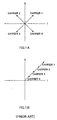
- FIG. 1A shows a case where the phases of four subcarriers 1 through 4 of an OFDM modulated wave are at 90 degree intervals. As the subcarrier frequencies are different, the subcarriers actually rotate at different angular frequencies, and FIG.1A shows observation at a predetermined time. In this case, subcarriers 1 through 4 cancel each other out, and the resultant vectors of subcarriers 1 through 4 are canceled, giving an amplitude of 0.
- FIG.1B shows a case where four subcarriers 1 through 4 are all aligned in the same phase.
- the resultant vectors of subcarriers 1 through 4 are added in the same phase, and therefore the resultant vector amplitude is 4 times that of one subcarrier.
- the OFDM modulated wave subcarrier phases coincide and a large-amplitude peak occurs in the OFDM modulated wave.
- Such large-amplitude peak power has an effect on the power amplifier. For example, if it is attempted to implement a power amplifier that can allow such large-amplitude peak power, the power amplifier configuration becomes complex and power consumption also increases. This also makes the configuration of circuitry such as A/D conversion circuits more complex. Moreover, if transmission is performed with large-amplitude peak power amplified directly, there is a basic problem of interference with other signals.
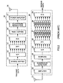
- transmitting apparatus 10 transmit data is converted by a symbol mapper 11 to a complex symbol sequence for modulating each carrier.
- Symbol mapper 11 is a section for converting multi-bit data to corresponding complex symbols, and has a configuration in accordance with the symbol modulation method.
- a generated complex symbol sequence is accumulated in a serial/parallel conversion section (S/P) 12.
- N accumulated symbols are converted by an inverse fast Fourier transform section (IFFT) 13, and an OFDM symbol sample value is generated.
- the obtained sample value is converted to a time series signal by a parallel/serial conversion section (P/S) 14, and a complex baseband OFDM signal is generated.
- P/S parallel/serial conversion section
- transmitting apparatus 10 multiplies the real part of the complex baseband signal after peak clipping by the carrier by means of a quadrature modulation section 16, and forms a carrier band OFDM signal.
- the formed OFDM signal is amplified by a power amplifier 17, and then radiated from an antenna 18.
- a received signal received by an antenna 21 is amplified by an amplifier 22 and then input to a quadrature detection section 23.
- a signal that has undergone detection processing by quadrature detection section 23 is sampled by a sampling section 24, and a complex signal sequence is generated.
- N generated complex signal sequence samples are accumulated by a serial/parallel conversion section (S/P) 25.
- a fast Fourier transform section (FFT) 26 outputs a complex symbol sequence in which each carrier is modulated by executing fast Fourier transform processing on the N accumulated samples.
- Complex symbols for each carrier are demodulated by demodulation sections (DEM) 27, and are then subjected to a hard decision by decoding sections (DEC) 28, to become data bits.
- the data bits for each carrier are then converted to serial receive data by a parallel/serial conversion section (P/S) 29, and are output.
- the peak-clipped signal is naturally a distorted signal, and consequently the quality of the signal received on the receiving side degrades.
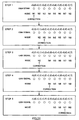
- FIG.3 shows an example of a transmit waveform when peak clipping processing is executed on the transmitting side.
- a solid line indicates an OFDM signal before peak clipping (example of 16 samples), and an example is shown in which peak clipping processing is carried out when the amplitude exceeds a threshold value of 7.
- the 2nd, 5th, and 10th samples exceed the threshold value, and therefore these amplitude values are clipped so as to become 7.
- real part and imaginary part data are as shown in the lower graphs, and data indicated by a dotted line differing from the data indicated by a solid line is received on the receiving side.
- the difference between the solid line and dotted line is distortion, and the reception quality degrades.
- This object is achievedby giving a Fourier transform processing circuit an FIR filter configuration that takes a sampling signal sampled from a received OFDM signal as variable gain and also has as input a Fourier transform known coefficient, selecting a sampling signal subject to correction as FIR filter variable gain, and converging the value of that sampling signal to an optimal value by means of an adaptive algorithm so that distortion and a noise component decrease.
- Sampling signals r(i,j) input to FFT 100 in FIG.4 are received OFDM signal sampling signals output from a serial/parallel conversion section (S/P) 25 in FIG.2 described above.
- S/P serial/parallel conversion section
- r(i, j) indicates the j'th sample received signal in the i'th OFDM symbol
- s(i,k) indicates the k' th subcarrier signal after FTT in the i'th OFDM symbol
- d(i,k) indicates the signal after synchronous detection of the k'th subcarrier in the i'th OFDM symbol
- f(i,k) indicates the hard decision value of the k'th subcarrier signal in the i'th OFDM symbol.
- time domain signals are first converted to frequency domain signals by having FFT processing executed on received signals r(i,j) by FFT 100.
- Demodulation sections (DEM) 101 obtain post-detection signals d(i,k) by performing synchronous detection (or differential detection) on subcarrier signals s(i,k).
- Decoding sections (DEC) 102 obtain receive data f(i,k) by executing a hard decision on post-detection signals d(i,k).
- t(i,k) indicates the k'th subcarrier signal found only from peak-clipped sampling signals in the i'th OFDM symbol
- u(i,k) indicates the k'th subcarrier signal found only from non-peak-clipped sampling signals in the i'th OFDM symbol.
- FFT 200 processing can be represented as shown in the following equation, using an FFT known coefficient w(j,k).
- Equation (1) can be implemented by the kind of circuit configuration shown in FIG.6. That is to say, the actual processing of FFT 200 that performs Fourier transform processing of peak-clipped sampling signals in FIG. 5 can be implemented by the kind of circuit shown in FIG.6.
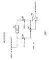
- circuit in FIG.6 is equivalent to the FIR filter 400 shown in FIG.7. That is to say, FFT 200 can be regarded as FIR filter 400 using variable gain r(i,j) with FFT 200 known coefficient w(j,k) as its input.
- the value of known coefficient w(j,k) is sequentially modified and input to a multiplier 402, and is also input to a multiplier 403 via a delay element 401, and multiplication is performed by multipliers 402 and 403 with peak-clipped sample signals as variable gain.
- the signals resulting from these multiplications are added by an adder 404, and the resulting signal is output via a switch 405.
- the number of subcarriers is 8, and therefore "m" in the figure is a value from 0 to 15.
- switch 405 outputs the addition result directly only when m is an odd number.
- the present inventors found that FFT processing can be implemented by means of an FIR filter with a known coefficient as its input and sample signals as variable gain.
- a signal that has not undergone peak clipping does not contain distortion other than noise, if a peak-clipped signal time waveform can be changed to a distortion-free waveform, it is possible to obtain an OFDM signal free of distortion due to peak clipping, etc.
- This is equivalent to converging variable gain r(i,1) and r(i,0) of FIR filter 400 in FIG.7 to an optimal value.
- the present inventors thus thought of converging variable gain (that is, peak-clipped sampling signals) to an optimal value through sequential correction while using an adaptive algorithm.
- FIG.8 shows the configuration of an OFDM signal correction section in an OFDM receiving apparatus of this embodiment.
- sampling signals r(i,0) through r(i,7) output from serial/parallel conversion section (S/P) 25 in FIG.2 are input to a selection section 501.
- selection section 501 Based on a selection signal from a tap selection section 502 as a selecting means that selects sampling signals subject to correction and sampling signals not subject to correction, from among sampling signals r(i,0) through r(i,7) selection section 501 sends sampling signals that have undergone peak clipping on the transmitting side to an FIR filter 503, and sends sampling signals that have not undergone peak clipping to an FTT 505.
- tap selection section 502 is provided in order to detect which of input sampling signals r(i,0) through r(i,7) are peak-clipped sampling signals.
- tap selection section 502 finds the ratio to average power in each sampling signal, and regards a sampling signal for which that ratio is greater than or equal to a certain threshold value as being a peak-clipped sampling signal.
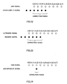
- the dashed line indicates the transmit signal waveform
- the solid line indicates the received signal waveform.
- tap selection section 502 by estimating peak-clipped sampling signals using a threshold value set lower than the transmitting-side peak clipping threshold value, it is possible to select peak-clipped sampling signals without missing any.
- sampling signals with sample numbers 4, 5, 6, 10, and 13 are selected as peak-clipped sampling signals.
- sampling signals with sample numbers 6 and 13 are actually sampling signals that have not been subjected to peak clipping, but there is no problem in terms of operation if these sampling signals are sent to FIR filter 503. In other words, in terms of improving reception quality this is preferable to overlooking peak-clipped sampling signals.
- FIR filter 503 FFT known coefficients are sequentially input as fixed input, and sampling signals estimated as having undergone peak clipping are input as tap coefficient initial values.
- FIR filter 503 output signal t(i,k) is sent to adders 506 via a serial/parallel conversion (S/P conversion) section 504.
- Post-FFT signals v(i,k) in each subcarrier obtained by adders 506 are input sequentially to demodulation sections (DEM) 507 and decoding sections (DEC) 508 as digital signal forming means, and undergo synchronous detection processing (or differential detection processing) by demodulation sections (DEM) 507 and hard decision processing by decoding sections (DEC) 508, as a result of which hard decision values f(i,k) - that is, received digital signals - are formed.
- a replica generating section 509 is also provided in the OFDM signal correction section.
- Replica generating section 509 generates replica signals x(i,k) corresponding to post-FFT signals v(i,k) in each subcarrier by multiplying hard decision values f(i,k) by the channel amplitude and phase (that is, executing the reverse of the processing by demodulation sections (DEM) 507) on a subcarrier-by-subcarrier basis.
- This channel amplitude and phase information may be obtained based simply on the amplitude value and phase rotation amount of a pilot signal, or may be obtained by impulse response detection.
- Difference values between post-FFT signals v(i,k) and replica signals x(i,k) are obtained by a subtracter 510, and these difference values are sent to an adaptive algorithm section 511 as error values e(i,k) of post-FFT signals v(i,k) and replica signals x(i,k).
- Adaptive algorithm section 511 is configured by means of LMS (Least Mean Square), RLS (Recursive Least Squares), GA (Generic Algorithm), etc., and sends to FIR filter 503 signals ordering correction of peak-clipped sampling signals r(i,j) used as FIR filter 503 variable gain so that error values e(i,k) are decreased.
- LMS Least Mean Square
- RLS Recursive Least Squares
- GA Generic Algorithm
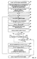
- the OFDM signal correction section effectively eliminates an interference component due to peak clipping included in an OFDM signal by carrying out the kind of reception processing shown in FIG.10.
- the description of each signal in FIG.8 includes the number of repetitions "m".
- variables in FIG.10 and FIG.8 have an upper-case to lower-case correspondence, so that, for example, V(i,k,m) in FIG. 10 is the value at the m'th repetition of v(i,k) in FIG.8.
- the error in the m'th repetition is designated E(i,k,m)
- the sample number j received signal updated using this is designated R(i,j,k,m).
- step S1 the OFDM signal correction section carries out channel estimation for each subcarrier by means of a channel estimation section (not shown) in order to perform detection in demodulation sections 507 and replica signal x(i,k) generation in replica generating section 509. Then in step S2, signal U(i,p) of each subcarrier is formed from only sampling signals that have not undergone peak clipping by having FFT 505 perform Fourier transform processing of sampling signals that have not undergone peak clipping.
- step S3 count value m of the OFDM signal correction section repetition counter (provided, for example, in the control section of the receiving apparatus in which the OFDM signal correction section is installed) is reset, and in the next step, S4, subcarrier number k is reset.
- k has a value from 0 to 7.
- step S5 FIR filter 503 takes an FFT known coefficient as input, and performs computation with interference area sample signals as variable gain, thereby sequentially forming signals T(i,q,m) of each subcarrier from peak-clipped sampling signals only.
- step S6 subcarrier signals T(i,q,m) sequentially obtained by FIR filter 503 undergo serial/parallel conversion by serial/parallel conversion section 504.
- step S7 addition signal V(i,k,m) is obtained by adding, with adder 506, peak-clipped sampling signal per-subcarrier signal T(i,k,m) obtained in steps S5 and S6, and non-peak-clipped per-subcarrier signal U(i,k) obtained in step S2 in the corresponding subcarriers.
- step S8 demodulated signal D(i,k,m) is obtained by having synchronous detection performed by demodulation section 507, and then in step S9, hard decision value F(i,k,m) is obtained by having a hard decision made by decoding section 508.
- step S10 it is determined whether or not the subcarrier number subject to adaptive algorithm processing this time is less than 8 (the number of subcarriers) , and if this subcarrier number is less than 8, the processing flow proceeds to step S11 and subcarrier number k is incremented. Then, in step S14, k'th subcarrier replica signal X(i,k,m) is generated by replica generating section 509, and in step S15 error value E(i,k,m) is found by finding the difference between k'th subcarrier replica signal X(i,k,m) and addition signal V(i,k,m) by means of subtracter 510.
- step S16 adaptive algorithm section 511 corrects FIR filter 503 variable gain (that is, peak-clipped sampling signal) R(i,j,m) so that error value E(i,k,m) is decreased, and this is sent to FIR filter 503.
- variable gain that is, peak-clipped sampling signal
- the OFDM signal correction section repeats the processing loop comprising steps S5-S6-S7-S8-S9-S10-S11-S14-S15-S16-S5 until the subcarrier number reaches 8.
- error value E(i,k,m) can be reduced as subcarrier number k increases and the distortion component is eliminated in proportion to the size of subcarrier number k, and a hard decision value F(i,k,m) with a small error rate can be output in step S9.
- step S10 when processing has been completed for 8 subcarriers, a negative result is obtained in step S10 and the processing flow proceeds to step S12, in which subcarrier number k is restored to 0 and repetition count value m is incremented. Then, in step S13, it is determined whether or not repetition count value m is less than a set maximum value Mmax, and if m is less than Mmax, the processing flow proceeds to step S14.
- the processing loop comprising steps S5-S6-S7-S8-S9-S10-S11-S14-S15-S16-S5 is then repeated until the subcarrier number reaches 8, in the same way as described above. Eventually, when the number of repetitions reaches Mmax, the processing flow proceeds to step S17 and reception processing for the i'th OFDM signal is terminated.
- the OFDM signal correction section sequentially converges variable gain R(i,j,k,m) using double loops based on repetition count m and subcarrier number k.
- error E(i,k,m) is gradually reduced, and in line with this the number of hard decision value F(i,k,m) errors decreases and error E(i,k,m) can also be made progressively smaller.
- a received signal that includes a distortion component due to peak clipping can be made to approach a distortion-free waveform.
- sampling signals sampled from a received OFDM signal are divided into peak-clipped sampling signals and non-peak-clipped sampling signals, Fourier transformprocessing is carried out separately for the peak-clipped sampling signals and non-peak-clipped sampling signals, and peak-clipped sampling signals are corrected so as to converge the error between replica signals x(i,k) generated from post-decoding signals and pre-modulation signals v(i,k) using an adaptive algorithm, thereby enabling the distortion component due to peak clipping to be eliminated.
- an FIR filter 503 and serial/parallel conversion section 504 are provided as a first Fourier transform processing section that performs Fourier transform processing on peak-clipped sampling signals
- an FFT 505 is provided as a second Fourier transform processing section that performs Fourier transform processing on non-peak-clipped sampling signals
- peak-clipped sampling signals and non-peak-clipped sampling signals are input together as FIR filter variable gain, and for that FIR filter variable gain to be corrected by means of an adaptive algorithm.
- the Fourier transform processing section with a fundamental Fourier transform processing function, in which a sampled received signal is divided into a plurality of subcarrier signals, and also with a function as a filter that eliminates a distortion component (hard decision error component) that appears as an error value between a replica signal and a signal resulting from Fourier transform processing.
- a fundamental Fourier transform processing function in which a sampled received signal is divided into a plurality of subcarrier signals, and also with a function as a filter that eliminates a distortion component (hard decision error component) that appears as an error value between a replica signal and a signal resulting from Fourier transform processing.
- Embodiment 1 a case was described in which, in estimating peak-clipped sampling signals, a ratio to average power is taken in each sampling signal sampled from a received OFDM signal, and a sampling signal for which this ratio exceeds a certain threshold value is regarded as a peak-clipped sampling signal.
- a provisional decision is first made on a received OFDM signal, a transmit waveform is generated by performing IFFT processing on the provisional decision data, and a sampling signal at a position that exceeds a predetermined threshold value in the generated transmit waveform system is selected as a peak-clipped sampling signal.
- FIG.11 is a block diagram showing the configuration of a tap selection section 800 according to this embodiment. Parts in FIG.11 identical to corresponding parts in FIG.2 are assigned the same codes as in FIG.2 and descriptions of these parts are omitted.
- tap selection section 800 sampling signals sampled from a received OFDM signal are converted to signals of each subcarrier by an FFT 801. The subcarrier signals undergo detection processing by demodulation sections 802, and then hard decision processing by a hard decision section 803, to become provisional decision data. The provisional decision data undergoes inverse Fourier transform processing by an IFFT 804. By this means the transmit waveforms are regenerated, and these regenerated waveforms are sent to peak determination sections 805.
- a threshold value Th equivalent to the transmitting-side threshold value ⁇ ⁇ is input to peak determination sections 805 from a multiplier 806, where ⁇ needs not be necessarily less than 1.
- Each peak determination section 805 compares the amplitude of the corresponding sampling point with threshold value Th. Sample numbers exceeding threshold value Th are then output to selection section 501 (FIG.8) as selection results.
- This embodiment takes note of the fact that, with regard to peak clipping, the phase of each sample is basically maintained, and correction need only be performed in the amplitude direction. Taking this into consideration, in the processing in adaptive algorithm section 511 (FIG. 8), a restriction is applied to the effect that only the amplitude direction of a received sampling signal is corrected. By this means, it is possible to make the adaptive algorithm suitable for elimination of distortion due to actual peak clipping, and also to shorten the convergence time.
- the vector of this sampling signal can be represented by the complex number A+jB.
- correction whereby a correction vector C+jD is applied to this sampling signal is then performed by means of an adaptive algorithm.
- pre-correction vector amplitude direction magnitude F sqrt (C 2 + D 2 ) cos(c-a).
- a restriction is applied to the effect that only the amplitude component is corrected by an adaptive algorithm, in the same way as in Embodiment 3.
- Embodiment 3 within the correction vector, only the pre-correction sample vector (received sample vector) direction component was used in correction
- this embodiment as shown in FIG. 13, a sampling point P2' at which a correction vector is added to the pre-correction vector is first found, and a new sampling point P2 is found by restoring the phase only in the pre-correction sample vector direction while maintaining the amplitude of sampling point P2'.
- phase direction noise is not caused by peak clipping. Therefore, when amplitude is corrected so as to increase, phase error due to noise remains unchanged, and thus the absolute value of the error increases to the extent that the amplitude increases.
- phase direction correction is carried out after performing amplitude direction correction.
- phase direction correction is performed using a different weight from amplitude direction correction. This is illustrated in FIG. 14.
- sampling point P3 at which only amplitude direction correction is performed is found using the same method as in Embodiment 4.
- new sampling point P4 is found by rotating sampling point P3 by the phase obtained by multiplying phase difference (d) from the post-correction vector by a constant r, where r is a positive number less than 1.
- r a positive number less than 1.
- an OFDM signal correction method is proposed that enables correction accuracy to be significantly improved in the event of multipathing on the propagation path.
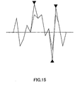
- an OFDM signal is subjected to peak clipping as shown in FIG.15.
- the horizontal axis indicates samples, and the vertical axis indicates the signal waveform in those samples.
- Black triangles indicate peak-clipped samples.
- the solid line shows the original waveform, and dashed lines show the peak-clipped waveform.
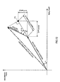
- FIG.16 shows an example in which three paths arrive at amplitudes of 1, 1, and -1 due to conditions on the three paths.
- the first path is indicated by a bold line, the second by a fine line, and the third by a dashed line.
- FIG.17 A waveform that combines these three is shown in FIG.17.
- wave distortion suffered by a peak-clipped symbol applies to only 3 samples in the case of one path, this has increased to 7 samples (the number of black triangles has increased).
- time domain impulse response precision also falls as the number of paths increases, so that correction precision will probably decline.
- multipath signals be restored to a single-path signal by performing frequency axis equalization on the multipath signals.
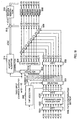
- FIG.18 in which parts corresponding to those in FIG.8 are assigned the same codes as in FIG.8, shows the configuration of an OFDM signal correction section of Embodiment 6.
- the OFDM signal correction section of this embodiment has a path compensation section 1000 that compensates for the effects of received OFDM multipath signals.
- sampling signals r(i,0) through r(i,7) are input to an FFT 1001 provided as a Fourier transform processing means.
- FFT 1001 extractssamplingsignalssuperimposedoneachsubcarrier by executing Fourier transform processing on sampling signals r(i,0) through r(i,7).
- the extracted subcarrier signals are sent to a frequency axis equalization section 1002.
- Frequency axis equalization section 1002 eliminates multipath influence on a subcarrier-by-subcarrier basis by performing complex division of each subcarrier signal by a channel estimation value for each subcarrier.
- frequency axis equalization is a known technique, it will not be explained in detail here. What is necessary, for example, is to estimate per-subcarrier amplitude and phase fluctuations based on a known signal superimposed on each subcarrier, and based on these estimates, restore subcarrier signals that have slumped due to frequency selective fading caused by multipath propagation to their original state.
- Subcarrier signals from which multipath influence has been eliminated by frequency axis equalization section 1002 - that is, subcarrier signals compensated to single-path signals - are restored to the same waveform as sampling signals obtained from a received OFDM signal by means of an IFFT (inverse fast Fourier transform section) 1003 provided as an inverse fast Fourier transform processing means, and then sent to selection section 501 and tap selection section 502, after which the same kind of processing is performed as in Embodiments 1 through 5.
- IFFT inverse fast Fourier transform section
- demodulation sections (DEM) 507 (FIG.8) required in Embodiments 1 through 5 can be omitted, as shown in FIG.18. This is because when multipath influence is eliminated by frequency axis equalization section 1002, amplitude and phase compensation is performed for each subcarrier signal. Also, as equalization on the frequency axis also corrects phase, the effect of sampling points shifting between transmission and reception (seen as each subcarrier undergoing phase fluctuation proportional to the subcarrier number) can also be eliminated.
- FIG.20 in which parts corresponding to those in FIG.18 are assigned the same codes as in FIG.18, shows the configuration of an OFDM signal correction section of Embodiment 7.
- the OFDM signal correction section of this embodiment has a power detection section 1100 that detects the reception power of each subcarrier signal.
- Power detection section 1100 detects the reception power of each subcarrier based on a known signal superimposed on each subcarrier, and sends the detection results to a selection section 1101.
- Selection section 1101 selects from error values e(i,k) of input subcarriers k only error values e(i,k) corresponding to a predetermined number of subcarriers from the highest reception power. Specifically, error values e(i,k) are output directly for the predetermined number of subcarriers from the highest reception power, and a value of 0 is output for subcarriers k with lower reception power.
- selection section 1101 is provided after subtracter 510, and signals of subcarriers with low signal power are excluded from correction by selecting 0 as the error value of a signal of a subcarrier with low reception power
- the present invention is not limited to this, and it is also possible, for example, to input results of detection by power detection section 1100 to adaptive algorithm section 511, and select subcarrier signals that are not to be reflected in the adaptive algorithm by means of adaptive algorithm section 511.
- sampling signals receiving interference by another user's signal by means of tap selection section 502 in FIG.8, send the selected sampling signals to FIR filter 503, and send sampling signals not receiving interference to FTT 505.
- This selection can be implemented by detecting sampling signal power, for example.
- FIG.22 shows an example of a correction range (sampling signals selected as subject to interference elimination).
- sampling signals r(i,0) through r(i,7) sampled from a received OFDM signal sampling signals r(i,0) through r(i,3) that temporally overlap another user's signal are sent to FIR filter 503, and remaining sampling signals r(i,4) through r(i,7) are sent to FTT 505.
- an inbound signal and outbound signal are transmitted using the same frequency divided on a time basis.
- the inbound signal and outbound signal may overlap temporally. For example, if a terminal is distant, a signal may be delayed due to radio wave transmission delay.
- sampling signals receiving interference between inbound and outbound signals by means of tap selection section 502 in FIG.8, send the selected sampling signals to FIR filter 503, and send sampling signals not receiving interference to FTT 505.
- This selection can be implemented by detecting sampling signal power, for example.
- FIG.23 shows an example of a correction range.
- sampling signals r(i, 0) through r(i,7) sampled from a received OFDM signal sampling signals r(i,0) through r(i,3) for which there is temporal overlap between inbound and outbound signals are sent to FIR filter 503, and remaining sampling signals r(i,4) through r(i,7) are sent to FTT 505
- Noise may occur in impulse form. In such cases, it is sufficient to correct only sampling signal r(i,2) corresponding to the interference signal, as shown in FIG.24.
- r(i,2) corresponding to the interference signal
- FIG.24 When, for example, another system uses the same frequency and that system generates spike noise (which is particularly prone to generation in UWB (ultra-wideband) systems) , there is a possibility of some sampling signals degrading.
- Impulse noise can be eliminated satisfactorily by detecting these degraded sampling signals by means of power detection or a sample round-robin method, etc., and sending sampling signals selectively to FIR filter 503 in FIG.8.
- sampling signal r(i,0) is input to FIR filter 503, then only sampling signal r(i,1) is input to FIR filter 503, and so on, so that only one sampling signal is input to FIR filter 503 and the other sampling signals are input to FTT 505.
- the SN ratio or error sum of squares of a demodulated signal at the time of correction when each sampling signal is input to FIR filter 503 is found.
- the fact that the SN ratio or error sum of squares when a certain sampling signal is corrected is large means that the noise of that sampling signal is large. In this way, noise magnitude is ranked for sampling signals r(i,0) through r(i,7), as shown in FIG.25 (b).
- Step 1 sampling signal r (i, 0) for which noise has been determined to be the largest is input to FIR filter 503, thereby eliminating the noise component of this sampling signal r(i,0).
- Step 2 sampling signal r(i,2) for which noise has been determined to be the second largest is input to FIR filter 503, thereby eliminating the noise component of this sampling signal r(i,2).
- FIR filter 503 By thus sequentially inputting sampling signals to FIR filter 503 in order from the sampling signal determined to have the largest noise, and eliminating the noise, it is possible for white noise to be eliminated satisfactorily from a received OFDM signal in which white noise is superimposed as noise.
- An OFDM receiving apparatus of the present invention has a configuration comprising a Fourier transform processing section provided with an FIR filter that takes a sampling signal sampled from a received OFDM signal as variable gain and also has as input a Fourier transform known coefficient, and a serial/parallel conversion section that forms a sampling signal superimposed on each subcarrier by performing serial/parallel conversion of the output of that FIR filter; a digital signal forming section that obtains a received digital signal from a sampling signal of each subcarrier obtainedby the Fourier transform processing section; a replica signal generation section that generates a replica signal of the sampling signal of each subcarrier from the received digital signal obtained by the digital signal forming section; an error calculation section that calculates an error value of corresponding subcarrier signals between a signal after Fourier transform processing obtained by the Fourier transform processing section and a replica signal; and a correction section that performs adaptive algorithm processing that decreases an error value by adaptively correcting the value of a sampling signal used as FIR filter variable gain according to the error value.
- the Fourier transform processing section can be given a fundamental Fourier transform processing function of converting a sampling signal sampled from a received OFDM signal to a signal superimposed on each subcarrier, and can also be given a function as a filter that eliminates distortion due to peak clipping processing or the like and a noise component that appears as an error value between a replica signal and a signal after Fourier transform processing. Then, by means of adaptive algorithm processing by the correction section, distortion and noise contained in a received OFDM signal can be effectively eliminated by adaptively correcting variable gain (a sampling signal sampled from a received OFDM signal) of an FIR filter of the Fourier transform processing section.
- An OFDM receiving apparatus of the present invention has a configuration further comprising a selection section that selects a sampling signal subject to correction and a sampling signal not subject to correction respectively from among sampling signals; wherein a Fourier transform processing section is provided with a first Fourier transform processing section that performs Fourier transform processing on a sampling signal subject to correction, a second Fourier transform processing section that performs Fourier transform processing on a sampling signal not subj ect to correction, and an addition section that adds signals of each subcarrier formed by the first and second Fourier transform processing sections in corresponding subcarrier signals; and the first Fourier transform processing section is provided with an FIR filter that takes a sampling signal subject to correction as variable gain and also has as input a Fourier transform known coefficient, and a serial/parallel conversion section that forms a sampling signal superimposed on each subcarrier by performing serial/parallel conversion of the output of that FIR filter.
- the Fourier transform processing section is divided into first and second Fourier transform processing sections, of which the first Fourier transform processing section that performs Fourier transform processing of sampling signals subject to correction has a configuration comprising an FIR filter, and by performing adaptive filtering using adaptive algorithm processing only on sampling signals subject to correction, it is possible to correct only sampling signals on which distortion or noise is actually superimposed, thereby enabling the amount of computational processing by the adaptive algorithm to be reduced. As a result, distortion or a noise component can be eliminated in a shorter time and more efficiently.
- An OFDM receiving apparatus of the present invention has a configuration further comprising a selection section that selects a sampling signal that has undergone peak clipping on the transmitting side and a sampling signal that has not undergone peak clipping respectively from among sampling signals; wherein a Fourier transform processing section is provided with a first Fourier transform processing section that performs Fourier transform processing on a sampling signal that has undergone peak clipping, a second Fourier transform processing section that performs Fourier transform processing on a sampling signal that has not undergone peak clipping, and an addition section that adds signals of each subcarrier formed by the first and second Fourier transform processing sections in corresponding subcarrier signals; and the first Fourier transform processing section is provided with an FIR filter that takes a sampling signal that has undergone peak clipping as variable gain and also has as input a Fourier transform known coefficient, and a serial/parallel conversion section that forms a sampling signal superimposed on each subcarrier by performing serial/parallel conversion of the output of that FIR filter.
- the Fourier transform processing section is divided into first and second Fourier transform processing sections, of which the first Fourier transform processing section that performs Fourier transform processing of sampling signals that have undergone peak clipping has a configuration comprising an FIR filter, and by performing adaptive filtering using adaptive algorithm processing only on sampling signals that have undergone peak clipping, it is possible to correct only sampling signals on which a distortion component due to peak clipping is actually superimposed, thereby enabling the amount of computational processing by the adaptive algorithm to be reduced. As a result, a distortion component due to peak clipping can be eliminated in a shorter time and more efficiently.
- An OFDM receiving apparatus of the present invention has a configuration wherein a selection section compares each sampling signal with a predetermined threshold value, and selects a sampling signal greater than or equal to the thresholdvalue as a sampling signal that has undergone peak clipping.
- sampling signals that have undergone peak clipping can be selected comparatively simply.
- An OFDM receiving apparatus of the present invention has a configuration wherein a selection section comprises a Fourier transform processing section that executes Fourier transform processing on a sampling signal, a provisional decision section that makes a provisional decision on data after Fourier transform processing, an inverse Fourier transform processing section that regenerates a transmit waveform by executing inverse Fouriertransform processing on provisionaldecision data obtained by that provisional decision section, and a selection section that selects a sampling signal greater than or equal to a predetermined threshold value within the regenerated waveform as a sampling signal that has undergone peak clipping.
- a transmit waveform is regenerated from provisionally decided provisional decision data, and sampling signals that have undergone peak clipping are estimated and selected based on sampling signals of the regenerated waveform, thereby enabling sampling signals that have undergone peak clipping to be selected with good precision.
- An OFDM receiving apparatus of the present invention has a configuration wherein the aforementioned threshold value is set as a value smaller than the threshold value used for peak clipping on the transmitting side.
- sampling signals that have undergone peak clipping can be selected without any being missed.
- An OFDM receiving apparatus of the present invention has a configuration wherein a correction section, in adaptively correcting the value of a sampling signal in accordance with an adaptive algorithm, corrects only the amplitude component and not the phase component of that sampling signal.
- real part I and imaginary part Q of a post-correction sampling signal are found based on post-correction vector length sqrt ((A+C) 2 +(B+D) 2 ) after correction of a sampling signal vector by a correction vector, making it possible to perform satisfactorily computation to which is attached the condition that only the amplitude component is to be corrected in an adaptive algorithm.
- An OFDM receiving apparatus of the present invention has a configuration wherein a correction section, in adaptively correcting the value of a sampling signal in accordance with an adaptive algorithm, corrects the phase component of the sampling signal after correcting only the amplitude component of the sampling signal.
- phase direction fluctuation when there is fluctuation in the phase direction in addition to error due to amplitude direction distortion caused by peak clipping, this phase direction fluctuation can also be corrected effectively. Specifically, when only the amplitude component of a sampling signal is first corrected, phase error arising due to propagation path fluctuations remains unchanged, and thus the absolute value of the error increases to the extent that the amplitude increases. By next performing phase direction correction to correct that error, it is possible to correct effectively the phase direction fluctuation component increased by increasing the amplitude.
- An OFDM receiving apparatus of the present invention has a configuration further comprising a path compensation section that compensates for fluctuations due to received OFDM multipath propagation, wherein a Fourier transform processing section takes a sampling signal compensated by that path compensation section as FIR filter variable gain.
- An OFDM receiving apparatus of the present invention has a configuration wherein a path compensation section comprises a Fourier transform processing section that extracts a sampling signal superimposed on each subcarrier by executing Fourier transform processing on a sampling signal sampled from a received OFDM signal, a frequency axis equalization section that executes frequency axis equalization processing on the sampling signal of each subcarrier, and an inverse Fourier transform processing section that executes inverse Fourier transform processing on the sampling signal of each subcarrier on which frequency axis equalization processing has been executed; and wherein a sampling signal after inverse Fourier transform processing is output as FIR filter variable gain.
- amplitude and phase fluctuations due to multipath propagation are eliminated on a subcarrier-by-subcarrier basis by means of frequency axis equalization and a single-path signal is formed, and correction processing is performed on this single-path signal by a Fourier transform processing section, digital signal forming section, replica signal generation section, error calculation section, and correction section, making it possible to improve the precision of correction in a multipath environment.
- An OFDM receiving apparatus of the present invention has a configuration further comprising a fluctuation detection section that detects fluctuations of each subcarrier signal due to multipath propagation from a received OFDM signal, and a selection section that selects a subcarrier signal to be corrected based on that detection result.
- An OFDM receiving apparatus of the present invention has a configuration wherein a fluctuation detection section detects the reception power of each subcarrier, and a selection section selects only a predetermined number of subcarrier signals from the highest reception power.
- An OFDM receiving apparatus of the present invention has a configuration wherein a fluctuation detection section detects the reception SN ratio of each subcarrier, and a selection section selects only a predetermined number of subcarrier signals with the largest reception SN ratios.
- An OFDM signal correction method of the present invention comprises a Fourier transform processing step of executing Fourier transform processing on a received OFDM signal by taking a sampling signal sampled from the received OFDM signal as variable gain and also performing FIR filter computation with a Fourier transform known coefficient as input, a digital signal forming step of obtaining a received digital signal from a sampling signal corresponding to each subcarrier obtained by the Fourier transform processing step, a replica signal generating step of generating a replica signal of the sampling signal of each subcarrier from the received digital signal obtained by the digital signal forming step, an error calculating step of calculating an error value of corresponding subcarrier signals between a signal after Fourier transform processing obtained by the Fourier transform processing step and a replica signal, and an adaptive algorithm processing step of decreasing an error value by adaptively correcting the value of a sampling signal of a receivedOFDM signal used as FIR filter variable gain according to the error value.
- the Fourier transform processing step it is possible to perform fundamental Fourier transform processing of converting a sampling signal sampled from a received OFDM signal to a signal superimposed on each subcarrier, and also to provide a function as a filter that eliminates distortion and a noise component that appear as an error value between a replica signal and a signal after Fourier transform processing. Then, in the adaptive algorithm processing step, distortion and a noise component can be effectively eliminated by adaptively correcting variable gain (a sampling signal sampled from a received OFDM signal) used in the Fourier transform processing step.
- An OFDM signal correction method of the present invention further includes a selecting step of selecting sampling signals subject to correction and sampling signals not subject to correction respectively from sampling signals sampled from a received OFDM signal; and in a Fourier transformprocessing step, for a sampling signal taken as subj ect to correction, takes that sampling signal as variable gain and performs FIR filter computation with a Fourier transform known coefficient as input, and for a sampling signal not subject to correction performs Fourier transform processing with the value of that sampling signal taken as 0, and adds and outputs the signal after FIR filter computation and the signal after Fourier transform processing.
- this method it is possible to perform adaptive filtering using adaptive algorithm processing only on sampling signals subject to correction, and to correct only sampling signals on which distortion or a noise component is actually superimposed, thereby enabling the amount of computational processing by the adaptive algorithm to be reduced. As a result, distortion or a noise component can be eliminated in a shorter time and more efficiently.
- An OFDM signal correction method of the present invention further comprises a path compensating step of compensating for fluctuations due to received OFDM multipath propagation, and a sampling signal compensated by that path compensating step is taken as FIR filter computation variable gain in a Fourier transform processing step.
- the present invention is applicable to an OFDM receiving apparatus that corrects distortion of an OFDM signal on which peak clipping processing has been executed at the time of transmission, for example.
Landscapes
- Engineering & Computer Science (AREA)
- Computer Networks & Wireless Communication (AREA)
- Signal Processing (AREA)
- Physics & Mathematics (AREA)
- Discrete Mathematics (AREA)
- General Physics & Mathematics (AREA)
- Mathematical Physics (AREA)
- Noise Elimination (AREA)
Applications Claiming Priority (5)
| Application Number | Priority Date | Filing Date | Title |
|---|---|---|---|
| JP2002180204 | 2002-06-20 | ||
| JP2002180204 | 2002-06-20 | ||
| JP2003001438A JP3715282B2 (ja) | 2002-06-20 | 2003-01-07 | Ofdm受信装置及びofdm信号の補正方法 |
| JP2003001438 | 2003-01-07 | ||
| PCT/JP2003/007707 WO2004002035A1 (ja) | 2002-06-20 | 2003-06-18 | Ofdm受信装置及びofdm信号の補正方法 |
Publications (2)
| Publication Number | Publication Date |
|---|---|
| EP1515468A1 true EP1515468A1 (de) | 2005-03-16 |
| EP1515468A4 EP1515468A4 (de) | 2006-01-18 |
Family
ID=30002251
Family Applications (1)
| Application Number | Title | Priority Date | Filing Date |
|---|---|---|---|
| EP03733476A Withdrawn EP1515468A4 (de) | 2002-06-20 | 2003-06-18 | Ofdm-empfangsvorrichtung und ofdm-signalkorrekturverfahren |
Country Status (6)
| Country | Link |
|---|---|
| US (1) | US20040247038A1 (de) |
| EP (1) | EP1515468A4 (de) |
| JP (1) | JP3715282B2 (de) |
| CN (1) | CN1568594A (de) |
| AU (1) | AU2003242452A1 (de) |
| WO (1) | WO2004002035A1 (de) |
Cited By (1)
| Publication number | Priority date | Publication date | Assignee | Title |
|---|---|---|---|---|
| CN104834248A (zh) * | 2014-02-12 | 2015-08-12 | 洛克威尔自动控制亚太业务中心有限公司 | 用于井监视的多用途数据处理电路 |
Families Citing this family (19)
| Publication number | Priority date | Publication date | Assignee | Title |
|---|---|---|---|---|
| JP4637822B2 (ja) | 2003-02-27 | 2011-02-23 | コーニンクレッカ フィリップス エレクトロニクス エヌ ヴィ | 高圧放電ランプ |
| US20090034407A1 (en) * | 2004-10-06 | 2009-02-05 | Lars Lindh | Receiver-site restoration of clipped signal peaks |
| KR100635011B1 (ko) * | 2004-11-16 | 2006-10-16 | 한국전자통신연구원 | 부채널수 변화에 따른 이득값 조절이 가능한직교주파수분할다중접속 시스템의 송신장치 및 그장치에서의 데이터 송신방법 |
| US8169890B2 (en) | 2005-07-20 | 2012-05-01 | Qualcomm Incorporated | Systems and method for high data rate ultra wideband communication |
| US8249513B2 (en) * | 2007-08-13 | 2012-08-21 | Samsung Electronics Co., Ltd. | System and method for training different types of directional antennas that adapts the training sequence length to the number of antennas |
| US8259828B2 (en) * | 2008-02-12 | 2012-09-04 | Mediatek Inc. | Sub-carrier alignment mechanism for OFDM multi-carrier systems |
| US8417191B2 (en) * | 2008-03-17 | 2013-04-09 | Samsung Electronics Co., Ltd. | Method and system for beamforming communication in high throughput wireless communication systems |
| US8478204B2 (en) | 2008-07-14 | 2013-07-02 | Samsung Electronics Co., Ltd. | System and method for antenna training of beamforming vectors having reuse of directional information |
| JP2010278850A (ja) * | 2009-05-29 | 2010-12-09 | Sharp Corp | 受信装置、受信方法、及び受信プログラム |
| JP2011049766A (ja) * | 2009-08-26 | 2011-03-10 | Sharp Corp | 無線受信装置、無線受信方法、及び無線受信プログラム |
| US9712276B2 (en) * | 2009-11-10 | 2017-07-18 | Lantiq Beteiligungs-GmbH & Co. KG | Error reporting in multi-carrier signal communication |
| JP5371722B2 (ja) * | 2009-12-11 | 2013-12-18 | シャープ株式会社 | 受信装置、受信方法、及び受信プログラム |
| US8855485B2 (en) | 2010-04-16 | 2014-10-07 | Nippon Telegraph And Telephone Corporation | Frequency offset estimating method and frequency offset estimating apparatus |
| US8804862B2 (en) * | 2012-01-09 | 2014-08-12 | King Fahd University Of Petroleum And Minerals | Method of performing peak reduction and clipping mitigation |
| US9608851B2 (en) | 2013-03-15 | 2017-03-28 | Jonathan Kanter | Turbo decoding techniques |
| US9191246B2 (en) * | 2013-03-15 | 2015-11-17 | Jonathan Kanter | Combined turbo decoding and turbo equalization techniques |
| FR3037202B1 (fr) | 2015-06-04 | 2017-07-07 | Stmicroelectronics Rousset | Procede et dispositif de transmission d'informations sur un canal de communication a impedance variable, en particulier pour un signal vehicule par courant porteur en ligne |
| CN106691439A (zh) * | 2015-07-28 | 2017-05-24 | 新加坡国立大学 | 多载波无线射频能量传输系统及方法 |
| CN111490954B (zh) * | 2020-04-03 | 2021-08-10 | 武汉大学 | 信道脉冲响应的重要时延抽头选择方法及系统 |
Family Cites Families (11)
| Publication number | Priority date | Publication date | Assignee | Title |
|---|---|---|---|---|
| FR2732178A1 (fr) * | 1995-03-22 | 1996-09-27 | Philips Electronique Lab | Systeme de transmission numerique muni d'un recepteur a egaliseurs cascades |
| JP3462373B2 (ja) * | 1996-08-30 | 2003-11-05 | 株式会社東芝 | マルチキャリア伝送装置 |
| EP0912023A1 (de) * | 1997-10-27 | 1999-04-28 | Alcatel | Demodulierung und Entzerrung von Mehrträgersignalen |
| US6898235B1 (en) * | 1999-12-10 | 2005-05-24 | Argon St Incorporated | Wideband communication intercept and direction finding device using hyperchannelization |
| EP1157512A1 (de) * | 1999-12-30 | 2001-11-28 | Bandspeed, Inc. | Verfahren zur verarbeitung von einem kommunikationskanal empfangenen daten bei anwendungen begrenzter arithmetischer präzision |
| US6507606B2 (en) * | 2000-03-29 | 2003-01-14 | Symmetrican, Inc. | Asymmetric digital subscriber line methods suitable for long subscriber loops |
| US6990083B1 (en) * | 2000-10-27 | 2006-01-24 | Tioga Technologies, Ltd. | Method and device for computing echo-cancellation coefficients using FFT |
| US6868114B2 (en) * | 2001-01-18 | 2005-03-15 | The Titan Corporation | Interference suppression in a spread spectrum communications system using non-linear frequency domain excision |
| CN1488209A (zh) * | 2001-08-28 | 2004-04-07 | ���µ�����ҵ��ʽ���� | 多径干扰消除设备和多径干扰消除方法 |
| US7113559B2 (en) * | 2001-09-24 | 2006-09-26 | Atheros Communications, Inc. | Efficient methods for filtering to avoid inter-symbol interference and processing digital signals having large frequency guard bands |
| US7088791B2 (en) * | 2001-10-19 | 2006-08-08 | Texas Instruments Incorporated | Systems and methods for improving FFT signal-to-noise ratio by identifying stage without bit growth |
-
2003
- 2003-01-07 JP JP2003001438A patent/JP3715282B2/ja not_active Expired - Fee Related
- 2003-06-18 AU AU2003242452A patent/AU2003242452A1/en not_active Abandoned
- 2003-06-18 US US10/494,685 patent/US20040247038A1/en not_active Abandoned
- 2003-06-18 WO PCT/JP2003/007707 patent/WO2004002035A1/ja not_active Ceased
- 2003-06-18 CN CN03801259.6A patent/CN1568594A/zh active Pending
- 2003-06-18 EP EP03733476A patent/EP1515468A4/de not_active Withdrawn
Cited By (1)
| Publication number | Priority date | Publication date | Assignee | Title |
|---|---|---|---|---|
| CN104834248A (zh) * | 2014-02-12 | 2015-08-12 | 洛克威尔自动控制亚太业务中心有限公司 | 用于井监视的多用途数据处理电路 |
Also Published As
| Publication number | Publication date |
|---|---|
| EP1515468A4 (de) | 2006-01-18 |
| US20040247038A1 (en) | 2004-12-09 |
| WO2004002035A1 (ja) | 2003-12-31 |
| AU2003242452A1 (en) | 2004-01-06 |
| JP3715282B2 (ja) | 2005-11-09 |
| JP2004080731A (ja) | 2004-03-11 |
| CN1568594A (zh) | 2005-01-19 |
Similar Documents
| Publication | Publication Date | Title |
|---|---|---|
| EP1515468A1 (de) | Ofdm-empfangsvorrichtung und ofdm-signalkorrekturverfahren | |
| JP4523294B2 (ja) | 通信装置 | |
| US7009932B2 (en) | Frequency tracking device for a receiver of a multi-carrier communication system | |
| EP1418720B1 (de) | Empfänger in einem OFDM-Übertragungssystem | |
| RU2454808C2 (ru) | Схема модуляции на нескольких несущих, а также передающее устройство и приемное устройство, использующие указанную схему | |
| CN101341677B (zh) | 载波间干涉去除装置及使用其的接收装置 | |
| JP4958565B2 (ja) | 無線通信装置 | |
| US7974350B2 (en) | Propagation path estimation method and apparatus | |
| EP0920163B1 (de) | Schätzung des groben Frequenzversatzes in Mehrträgerempfängern | |
| US20060294170A1 (en) | Diversity receiver device | |
| EP1422850A1 (de) | Störungsentfernungsvorrichtung und verfahren mit mehreren durchgängen | |
| US8363539B2 (en) | OFDM receiver and OFDM receiving method | |
| US20070070879A1 (en) | Multi-user receiving apparatus converting SC-FDMA received signals of all users to signals in a frequency domain commonly | |
| JP4644978B2 (ja) | Ofdm通信システム、ofdm通信方法およびofdm通信装置 | |
| JP2008532354A (ja) | 向上されたブロック等化を提供する無線通信装置及び関連する方法 | |
| JP2001086092A (ja) | Ofdm通信装置および検波方法 | |
| CN101529766A (zh) | 接收方法和接收器 | |
| US20060209974A1 (en) | Propagation path estimating method and apparatus | |
| CN103312643B (zh) | 均衡装置、接收装置和均衡方法 | |
| JP2008530906A (ja) | 過去、現在及び/又は将来の自己相関マトリクスの予測値に基づいてブロック等化を実行する無線通信装置及び関連する方法 | |
| KR100213100B1 (ko) | Ofdm 전송 신호의 주파수 오류 정정기와 그 방법 | |
| US20080298227A1 (en) | Method for Interference Estimation for Orthogonal Pilot Patterns | |
| JP2014135605A (ja) | 受信装置 | |
| JP2008148277A (ja) | Ofdm信号合成用受信装置および中継装置 | |
| KR20070087216A (ko) | 후검출 컨스텔레이션 보정을 위한 무선 통신 방법 및 장치 |
Legal Events
| Date | Code | Title | Description |
|---|---|---|---|
| PUAI | Public reference made under article 153(3) epc to a published international application that has entered the european phase |
Free format text: ORIGINAL CODE: 0009012 |
|
| 17P | Request for examination filed |
Effective date: 20040827 |
|
| AK | Designated contracting states |
Kind code of ref document: A1 Designated state(s): AT BE BG CH CY CZ DE DK EE ES FI FR GB GR HU IE IT LI LU MC NL PT RO SE SI SK TR |
|
| AX | Request for extension of the european patent |
Extension state: AL LT LV MK |
|
| RIN1 | Information on inventor provided before grant (corrected) |
Inventor name: OTA, EIJI,C/O TOKYO DENPAN SEKKEI INC. Inventor name: UESUGI, MITSURU |
|
| DAX | Request for extension of the european patent (deleted) | ||
| RBV | Designated contracting states (corrected) |
Designated state(s): DE FR GB |
|
| A4 | Supplementary search report drawn up and despatched |
Effective date: 20051206 |
|
| STAA | Information on the status of an ep patent application or granted ep patent |
Free format text: STATUS: THE APPLICATION IS DEEMED TO BE WITHDRAWN |
|
| 18D | Application deemed to be withdrawn |
Effective date: 20060811 |