EP1515211B1 - Kapazitiver Berührungsschalter für elektrische Fensterheber oder Schiebedach - Google Patents
Kapazitiver Berührungsschalter für elektrische Fensterheber oder Schiebedach Download PDFInfo
- Publication number
- EP1515211B1 EP1515211B1 EP04360076A EP04360076A EP1515211B1 EP 1515211 B1 EP1515211 B1 EP 1515211B1 EP 04360076 A EP04360076 A EP 04360076A EP 04360076 A EP04360076 A EP 04360076A EP 1515211 B1 EP1515211 B1 EP 1515211B1
- Authority
- EP
- European Patent Office
- Prior art keywords
- finger
- controlling
- variation
- fact
- movable wall
- Prior art date
- Legal status (The legal status is an assumption and is not a legal conclusion. Google has not performed a legal analysis and makes no representation as to the accuracy of the status listed.)
- Expired - Lifetime
Links
- 238000001514 detection method Methods 0.000 claims description 15
- 238000006073 displacement reaction Methods 0.000 claims description 15
- 238000000034 method Methods 0.000 claims description 9
- 239000011521 glass Substances 0.000 description 2
- 239000002184 metal Substances 0.000 description 2
- 239000008188 pellet Substances 0.000 description 2
- 241000861223 Issus Species 0.000 description 1
- 230000001627 detrimental effect Effects 0.000 description 1
- 239000000428 dust Substances 0.000 description 1
- 230000010365 information processing Effects 0.000 description 1
- 238000012986 modification Methods 0.000 description 1
- 230000004048 modification Effects 0.000 description 1
- 210000000056 organ Anatomy 0.000 description 1
Images


Classifications
-
- H—ELECTRICITY
- H03—ELECTRONIC CIRCUITRY
- H03K—PULSE TECHNIQUE
- H03K17/00—Electronic switching or gating, i.e. not by contact-making and –breaking
- H03K17/94—Electronic switching or gating, i.e. not by contact-making and –breaking characterised by the way in which the control signals are generated
- H03K17/96—Touch switches
- H03K17/962—Capacitive touch switches
-
- E—FIXED CONSTRUCTIONS
- E05—LOCKS; KEYS; WINDOW OR DOOR FITTINGS; SAFES
- E05F—DEVICES FOR MOVING WINGS INTO OPEN OR CLOSED POSITION; CHECKS FOR WINGS; WING FITTINGS NOT OTHERWISE PROVIDED FOR, CONCERNED WITH THE FUNCTIONING OF THE WING
- E05F15/00—Power-operated mechanisms for wings
- E05F15/60—Power-operated mechanisms for wings using electrical actuators
- E05F15/603—Power-operated mechanisms for wings using electrical actuators using rotary electromotors
- E05F15/665—Power-operated mechanisms for wings using electrical actuators using rotary electromotors for vertically-sliding wings
- E05F15/689—Power-operated mechanisms for wings using electrical actuators using rotary electromotors for vertically-sliding wings specially adapted for vehicle windows
- E05F15/695—Control circuits therefor
-
- E—FIXED CONSTRUCTIONS
- E05—LOCKS; KEYS; WINDOW OR DOOR FITTINGS; SAFES
- E05Y—INDEXING SCHEME ASSOCIATED WITH SUBCLASSES E05D AND E05F, RELATING TO CONSTRUCTION ELEMENTS, ELECTRIC CONTROL, POWER SUPPLY, POWER SIGNAL OR TRANSMISSION, USER INTERFACES, MOUNTING OR COUPLING, DETAILS, ACCESSORIES, AUXILIARY OPERATIONS NOT OTHERWISE PROVIDED FOR, APPLICATION THEREOF
- E05Y2400/00—Electronic control; Electrical power; Power supply; Power or signal transmission; User interfaces
- E05Y2400/10—Electronic control
- E05Y2400/32—Position control, detection or monitoring
- E05Y2400/35—Position control, detection or monitoring related to specific positions
-
- E—FIXED CONSTRUCTIONS
- E05—LOCKS; KEYS; WINDOW OR DOOR FITTINGS; SAFES
- E05Y—INDEXING SCHEME ASSOCIATED WITH SUBCLASSES E05D AND E05F, RELATING TO CONSTRUCTION ELEMENTS, ELECTRIC CONTROL, POWER SUPPLY, POWER SIGNAL OR TRANSMISSION, USER INTERFACES, MOUNTING OR COUPLING, DETAILS, ACCESSORIES, AUXILIARY OPERATIONS NOT OTHERWISE PROVIDED FOR, APPLICATION THEREOF
- E05Y2400/00—Electronic control; Electrical power; Power supply; Power or signal transmission; User interfaces
- E05Y2400/80—User interfaces
- E05Y2400/85—User input means
- E05Y2400/856—Actuation thereof
- E05Y2400/858—Actuation thereof by body parts, e.g. by feet
- E05Y2400/86—Actuation thereof by body parts, e.g. by feet by hand
-
- E—FIXED CONSTRUCTIONS
- E05—LOCKS; KEYS; WINDOW OR DOOR FITTINGS; SAFES
- E05Y—INDEXING SCHEME ASSOCIATED WITH SUBCLASSES E05D AND E05F, RELATING TO CONSTRUCTION ELEMENTS, ELECTRIC CONTROL, POWER SUPPLY, POWER SIGNAL OR TRANSMISSION, USER INTERFACES, MOUNTING OR COUPLING, DETAILS, ACCESSORIES, AUXILIARY OPERATIONS NOT OTHERWISE PROVIDED FOR, APPLICATION THEREOF
- E05Y2900/00—Application of doors, windows, wings or fittings thereof
- E05Y2900/50—Application of doors, windows, wings or fittings thereof for vehicles
- E05Y2900/53—Type of wing
- E05Y2900/55—Windows
Definitions
- the present invention relates to a device for controlling the variation of a physical parameter, more specifically the position of a movable wall of the window type of motor vehicle window, as well as to a method for the implementation of these measures.
- the side windows of a motor vehicle are usually controlled by pushbuttons arranged in consoles generally located at the doors or, at least for central control, on the center console located between the front seats of the vehicle. vehicle.
- the document FR - 2 829 522 describes a device for controlling the variation of a physical parameter operating by sliding a finger of the user on a resistive touchpad.
- the sliding causes the control of the variation of the physical parameter in a direction reflecting the direction of sliding of the finger.
- the document US-A-4,321,479 discloses a capacitive block whose operation is based on that of a control wheel: the movements of a finger in contact with a touch surface are analyzed so as to determine the direction and amplitude of the movement of the finger. This device is based on two shift registers storing two successive contact situations of the finger on the tactile surface.
- the present invention is also based on a very intuitive manipulation, during which the variation of the parameter is induced on a small scale by the movement of the finger of the user on a surface provided for this purpose.
- the control device operates by sliding a finger on this surface, causing the control of the variation of said physical parameter in a direction that reflects the direction of sliding of the finger on said surface.
- the steering of the variation is done in a very intuitive and immediate way.
- this system Compared to the devices of the prior art, when they consist of push buttons, this system has a high reliability because it no longer has mechanical parts moving relative to each other, subject in addition to repeated efforts , and which are therefore weak links in terms of reliability.
- the device of the invention devoid of any mobile mechanical part, has a small footprint since it comprises essentially only the detector plate and the electronic components arranged on a printed circuit. In the end, it leads to a thin product, which occupies a much lower volume than that required electromechanical switches of the prior art.
- This new concept is also not detrimental to the ergonomics of operation.
- the use is simple and intuitive, since the driving of windows for example is by a movement of the finger which schematically symbolizes the movement, in the direction of lifting or lowering, the window.
- the control finally requires virtually no reflection, because of its intuitive appearance, and the driver can implement it without absorbing some of the concentration required by the driving of the vehicle. Security is strengthened.
- the sensors that are used in the new control device are capacitive sensors.
- Capacitive technology allows a relatively light architecture, insensitive to dust, dirt, etc. Given its simplicity, this technology is also relatively inexpensive.
- control device of the invention consists of a plurality of capacitive sensors connected to the aforementioned electronic means and arranged on the one hand in line along the axis of the detector plate so as to model by their layout the variability of the position. of the wall, and secondly in the vicinity of said outer surface to detect the contact of the finger on said plate.
- the electronic processing means emit at least one signal defining the displacement of the moving wall at the drive means address of said wall, the processing means calculating the percentage of the path drawn by the sensors on the detector plate which is actually traveled by the user's finger, and controlling driving means so that the movable wall moves a fraction of its total path equal to the same percentage or a fraction equal to the calculated percentage of the distance remaining to travel to reach a stop.
- said sensors comprise at least one electrode connected to a cell for detecting the electric charge of the electrode.
- the electrodes relay the information relating to the existence of a contact on the detector plate, evidenced by a change in their electrical charge.
- Each sensor takes for example the form of metal pellets arranged in or on the detector plate.
- Each sensor is then connected to an input port of a microcontroller processing its signals and constituting the electronic information processing means, the output ports of which are connected to the circuit comprising the means for controlling the variations of the parameter constituting the drive means of the wall.
- the information provided by the sensors is therefore available in parallel on all input ports, providing a different code depending on the position of the finger on the sensor plate.
- the electrodes are more precisely arranged in line along the axis of the detector plate. The rectilinear movement of the finger on said plate, in one direction or another, is then sufficient to cause the movement of the opening in the required direction, for opening or closing.
- the sliding control device has a thickness which does not exceed 3 mm.
- the overall volume is therefore equivalent to a wafer of rectangular shape, and of reduced thickness.
- the central part of the treatment consists, once the detection of a finger contact with the detector plate performed, to compare the initial positioning with the subsequent positioning, in order to determine the direction of movement of the finger, and therefore the direction of control which is for example required for driving motor means of a window.
- At least one signal from the electronic processing means also defines the amplitude of the displacement variation.
- the processing means control the drive means of the movable wall so that it moves a fraction of its total path equal to the calculated percentage.
- the displacement of the window reflects homothetically that of the finger, obviously related to the entire length of the detector plate.
- the processing means control the drive means of the movable wall so that it moves by a fraction equal to the same percentage of the distance remaining to it. walk to get to the end.
- This type of displacement ensures a very precise adjustment of the position of the mobile wall.
- the signal controlling the control means stops being emitted by the processing means when, after several iterations, the same sensor or sensors are activated, indicating that the finger no longer moves.
- Immobilization of the finger is then interpreted by the system as indicating the desire of the user to stop varying the displacement of the movable wall of the window type of vehicle door.
- the signal driving the drive means may no longer be emitted by the processing means when no sensor is no longer activated, indicating that the finger is no longer in contact with the sensor plate.
- the microcontroller acting as electronic processing means, can in some cases manage, in addition to the positioning of the finger, its speed of movement.
- the processing means detect a movement of a finger along at least a predetermined number of sensors in a time less than a predetermined time, it can go into a fast drive mode of the drive means of the movable wall, which is then driven towards the stop marking the end of its displacement in the chosen direction.
- This function allows the quick closing / opening of the window. Conversely, when the detected speed is below the predetermined threshold, the window opens / closes at a lower speed, and only during the movement / contact of the finger on the sensor plate.
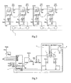
- the door portion (P) represented in figure 1 comprises near and at the opening handle of said door (P) an enlarged flat surface in the upper part of this same figure.
- This surface is made with a plate (1) detector in which are housed, in line, the electrodes for detecting the movement, or even the speed of movement, the finger of the user when it travels.
- the plate (1) comprises, in a rectilinear pattern that reflects the path of the movable wall that is to be controlled, electrodes that detect the position, and therefore the movement of the finger of the user.
- these electrodes take for example the form of pellets (2) metal, distributed along the fictitious path as reproduced in the plate (1).
- These electrodes (2) are each connected to a sensor cell (3), in this case a component specifically dedicated to this function.
- Each detection cell (3) has an output which gives the state of the capacitive detection, and which is connected to an input port of a microcontroller (4) appearing in figure 3 , in charge of the processing of these signals.
- the input ports here four in number, are respectively referenced RA0, RA1, RA2 and RA3.
- the output ports RC2 / PWM, RC4 and RC5 of the microcontroller (4) are themselves connected to a power circuit (5) responsible for controlling the engine designed to drive the window.
- Outputs RC4 and RC5 each drive the coil of a relay, said relays operating switches controlling a motor supply bridge, in order to give it a direction of rotation.
- the RC2 / PWM output is a pulse output, driving a MOSFET power transistor allowing the motor power supply on the one hand, and the management of its speed on the other hand. This rotational speed is controlled by the duty cycle which drives the MOSFET transistor.
- the RBO / INT input is configured as an interrupt input. It reports on the positioning of the window in relation to the end positions. In the event that a limit switch is reached, the program produces an interruption and an initialization. This input is activated by a current detector: it happens that when the windows reach their end of travel or an obstacle, a peak of current occurs in the power circuit. When this peak is detected, the engine is stopped by the information that arrives at the RBO / INT input.
- the figure 4 represents the main flowchart of the operation.
- the microcontroller searches for the address corresponding to the active inputs, which constitutes the address 1.
- the addresses 1 and 2 are compared, and the result of this comparison makes it possible to send a data either at the output RC4 or at the output RC5, in order to initiate a displacement upwards or downwards. low.
- the width of the control pulses transmitted in RC2 / PWM depends in particular on the speed and amplitude of the movement of the finger on the detector plate.
Landscapes
- Power-Operated Mechanisms For Wings (AREA)
- Window Of Vehicle (AREA)
Claims (10)
- Vorrichtung zur Steuerung der Änderung eines physikalischen Parameters, der aus der Stellung einer beweglichen Wand beispielsweise vom Typ Fahrzeugtür-Fensterscheibe besteht, die durch Gleiten eines Fingers des Benutzers auf einer Fläche arbeitet, das die Steuerung der Änderung dieser Stellung in einem Sinn mit sich bringt, der den Sinn des Gleitens des Fingers wiedergibt, umfassend eine Erfassungsplatte (1), die mit einer ebenen Außenfläche versehen, die dazu bestimmt ist, mit dem Finger in Kontakt zu kommen oder von ihm berührt zu werden, elektronische Mittel (4) zur Verarbeitung der von der Erfassungsplatte kommenden Information und zur Steuerung einer Schaltung (5), die Mittel zur Steuerung der Änderungen der Stellung umfasst, wobei diese Änderungen die Amplitude des Gleitens des Fingers auf der Erfassungsplatte (1) wiedergeben, dadurch gekennzeichnet, dass sie aus mehreren kapazitiven Fühlern (2, 3) besteht, die mit den elektronischen Mitteln (4) verbunden sind und einerseits in der Achse der Erfassungsplatte (1) in einer Linie angeordnet sind, so dass sie durch ihre Spur die Veränderlichkeit der Stellung der Wand modellisieren, und andererseits in Nähe der Außenfläche, um den Kontakt des Fingers auf der Platte (1) zu erfassen, und dass die elektronischen Verarbeitungsmittel (4) mindestens ein die Bewegung der beweglichen Wand definierendes Signal zur Adresse der Mittel zum Antrieb der Wand senden, wobei die Verarbeitungsmittel (4) den Prozentsatz des von den Fühlern (2, 3) auf der Erfassungsplatte (1) gezeichneten Wegs berechnen, der von dem Finger des Benutzers tatsächlich durchlaufen wird, und die Antriebsmittel so steuern, dass die bewegliche Wand sich um einen Bruchteil ihres Gesamtwegs, der gleich demselben Prozentsatz ist, oder um einen Bruchteil bewegt, der gleich dem berechneten Prozentsatz der Strecke ist, die sie noch bis zur Ankunft am Anschlag zu durchlaufen hat.
- Vorrichtung zur Steuerung der Änderung eines physikalischen Parameters nach dem vorhergehenden Anspruch, dadurch gekennzeichnet, dass die Fühler mindestens eine Elektrode (2) umfassen, die an eine Zelle (3) zur Erfassung der elektrischen Ladung der Elektrode (2) angeschlossen ist.
- Vorrichtung zur Steuerung der Änderung eines physikalischen Parameters nach dem vorhergehenden Anspruch, dadurch gekennzeichnet, dass die Elektroden (2) metallische Plättchen sind, die in oder auf der Erfassungsplatte (1) angeordnet sind.
- Vorrichtung zur Steuerung der Änderung eines physikalischen Parameters nach einem der vorhergehenden Ansprüche, dadurch gekennzeichnet, dass jeder Fühler (2, 3) mit einem Eingangsport eines Mikrosteuergeräts (4) verbunden ist, das seine Signale verarbeitet und die elektronischen Mittel zur Verarbeitung der Information bildet und dessen Ausgangsports mit der Schaltung (5) verbunden sind, die die Mittel zur Steuerung der Änderungen des Parameters umfasst, die die Mittel zum Antrieb der Wand bilden.
- Verfahren zur Steuerung der Änderung eines physikalischen Parameters, der aus der Stellung einer beweglichen Wand beispielsweise vom Typ Fahrzeugtür-Fensterscheibe besteht, mit Hilfe einer Steuervorrichtung nach einem der vorhergehenden Ansprüche, deren elektronische Mittel (4) zur Verarbeitung von von den Fühlern (2, 3) kommenden Signalen:- den Sinn der Bewegung des Fingers durch Vergleich der nacheinander durchlaufenen Stellungen bestimmen;mindestens ein den Sinn der Änderung definierendes Signal zur Adresse der Mittel zur Steuerung der Änderungen der Stellung der Wand senden,
dadurch gekennzeichnet, dass die elektronischen Verarbeitungsmittel:- darüber hinaus die Anfangsstellung des Fingers, wenn ein von mindestens einem Fühler (2, 3) kommendes Signal erfasst wird, durch Erkennen des oder der aktivierten Fühler (2, 3) bestimmen;- iterativ jede dann von dem Finger eingenommene Stellung berechnen, um die Amplitude des Gleitens des Fingers zu messen;- den Prozentsatz des von den Fühlern (2, 3) gezeichneten Wegs auf der Erfassungsplatte (1) berechnen, der von dem Finger des Benutzers tatsächlich durchlaufen wird; und- mindestens ein die Bewegung der beweglichen Wand definierendes Signal zur Adresse von Mitteln zum Antrieb der Wand senden. - Verfahren zur Steuerung der Bewegung einer beweglichen Wand nach Anspruch 5, dadurch gekennzeichnet, dass die Verarbeitungsmittel (4) die Mittel zum Antrieb der beweglichen Wand so steuern, dass sie sich um einen Bruchteil ihres Gesamtwegs bewegt, der gleich dem berechneten Prozentsatz ist.
- Verfahren zur Steuerung der Bewegung einer beweglichen Wand nach Anspruch 5, dadurch gekennzeichnet, dass die Verarbeitungsmittel die Mittel zum Antrieb der beweglichen Wand so steuern, dass sie sich um einen Bruchteil bewegt, der gleich dem berechneten Prozentsatz der Strecke ist, die sie noch bis zum Erreichen des Anschlags zu durchlaufen hat.
- Verfahren zur Steuerung der Änderung eines physikalischen Parameters nach einem der Ansprüche 5 bis 7, dadurch gekennzeichnet, dass das die Steuermittel steuernde Signal aufhört, von den Verarbeitungsmitteln (4) gesendet zu werden, wenn der oder dieselben Fühler (2, 3) nach mehreren Iterationen aktiviert sind, was anzeigt, dass der Finger sich nicht mehr bewegt.
- Verfahren zur Steuerung der Änderung eines physikalischen Parameters nach einem der Ansprüche 5 bis 7, dadurch gekennzeichnet, dass das die Steuermittel steuernde Signal aufhört, von den Verarbeitungsmitteln (4) gesendet zu werden, wenn kein Fühler (2, 3) mehr aktiviert wird, was anzeigt, dass der Finger nicht mehr mit der Erfassungsplatte (1) in Kontakt ist.
- Verfahren zur Steuerung der Änderung eines physikalischen Parameters nach einem der Ansprüche 5 bis 9, dadurch gekennzeichnet, dass, wenn die Verarbeitungsmittel (4) eine Bewegung des Fingers längs mindestens einer vorbestimmten Anzahl von Fühlern (2, 3) in einer Zeit von weniger als einer vorbestimmten Dauer erfassen, es in einen Modus des schnellen Antriebs der Mittel zum Antrieb der beweglichen Wand übergeht, die nun zum Anschlag mitgenommen wird, der das Ende ihrer Bewegung in dem gewählten Sinn markiert.
Applications Claiming Priority (2)
| Application Number | Priority Date | Filing Date | Title |
|---|---|---|---|
| FR0310632 | 2003-09-09 | ||
| FR0310632A FR2859525B1 (fr) | 2003-09-09 | 2003-09-09 | Commutateur capacitif glissant |
Publications (2)
| Publication Number | Publication Date |
|---|---|
| EP1515211A1 EP1515211A1 (de) | 2005-03-16 |
| EP1515211B1 true EP1515211B1 (de) | 2010-10-13 |
Family
ID=34130781
Family Applications (1)
| Application Number | Title | Priority Date | Filing Date |
|---|---|---|---|
| EP04360076A Expired - Lifetime EP1515211B1 (de) | 2003-09-09 | 2004-08-31 | Kapazitiver Berührungsschalter für elektrische Fensterheber oder Schiebedach |
Country Status (3)
| Country | Link |
|---|---|
| EP (1) | EP1515211B1 (de) |
| DE (1) | DE602004029539D1 (de) |
| FR (1) | FR2859525B1 (de) |
Cited By (1)
| Publication number | Priority date | Publication date | Assignee | Title |
|---|---|---|---|---|
| RU2727797C1 (ru) * | 2016-11-04 | 2020-07-24 | Сэн-Гобэн Гласс Франс | Конструкция оконного стекла с многослойным стеклом с расширенным емкостным коммутационным участком |
Families Citing this family (22)
| Publication number | Priority date | Publication date | Assignee | Title |
|---|---|---|---|---|
| US20080302014A1 (en) * | 2007-06-05 | 2008-12-11 | Gm Global Technology Operations, Inc. | Method and apparatus for positioning a motor actuated vehicle accessory |
| EP2481153B1 (de) | 2009-09-25 | 2020-07-15 | Saint-Gobain Glass France | Aktive verglasung mit integrierter anzeigevorrichtung, ein verfahren zur aktivierung oder deaktivierung der aktiven verglasung und deren verwendung |
| DE202009017952U1 (de) | 2009-09-25 | 2010-09-23 | Saint-Gobain Sekurit Deutschland Gmbh & Co. Kg | Verglasung mit integrierter Schaltvorrichtung |
| JP5905109B2 (ja) | 2011-10-10 | 2016-04-20 | サン−ゴバン グラス フランスSaint−Gobain Glass France | 照明されるスイッチ面を備えた板ガラス |
| ES2794100T3 (es) | 2014-04-24 | 2020-11-17 | Saint Gobain | Luna eléctricamente calentable con zona de conmutación |
| EA034011B1 (ru) | 2015-01-20 | 2019-12-18 | Сэн-Гобэн Гласс Франс | Многослойное стекло с емкостной зоной коммутации |
| US10523201B2 (en) | 2015-08-18 | 2019-12-31 | Saint-Gobain Glass France | Pane arrangement with pane with low-E coating and capacitive switching region |
| US10743375B2 (en) | 2015-11-06 | 2020-08-11 | Saint-Gobain Glass France | Pane assembly having a heatable composite pane having a capacitive switching region |
| WO2017077128A1 (de) | 2015-11-06 | 2017-05-11 | Saint-Gobain Glass France | Elektrisch beheizbare verbundscheibe mit kapazitivem schaltbereich |
| JP6791980B2 (ja) | 2016-05-23 | 2020-11-25 | サン−ゴバン グラス フランス | センサアセンブリを有している積層ガラスペイン、及び、センサアセンブリを有している積層ガラスペインを製造する方法 |
| DE102016007357A1 (de) * | 2016-06-15 | 2017-12-21 | GM Global Technology Operations LLC (n. d. Ges. d. Staates Delaware) | Kraftfahrzeugeinrichtung mit einer bewegbaren Fensterscheibe, Kraftfahrzeug mit einer solchen Kraftfahrzeugeinrichtung und Verfahren zum Betrieb einer solchen Kraftfahrzeugeinrichtung |
| EP3264242A1 (de) | 2016-06-29 | 2018-01-03 | Saint-Gobain Glass France | Berührungssteuerungsverglasungen mit kapazitiver berührungsempfindlicher vorrichtung und einer lichtemittierenden diode und herstellung davon |
| EP3264241A1 (de) | 2016-06-29 | 2018-01-03 | Saint-Gobain Glass France | Beleuchtetes verbundglas mit einer kapazitiven berührungsempfindlichen vorrichtung und einer leuchtdiode sowie und die herstellung |
| US10533362B2 (en) | 2017-06-16 | 2020-01-14 | GM Global Technology Operations LLC | Systems and methods for memory and touch position window |
| CN113365814A (zh) | 2020-01-06 | 2021-09-07 | 法国圣戈班玻璃厂 | 具有电容式传感器电极的车辆玻璃板装置 |
| WO2021185669A1 (de) | 2020-03-18 | 2021-09-23 | Saint-Gobain Glass France | Scheibenanordnung mit kapazitivem schaltbereich |
| DE202021004050U1 (de) | 2020-04-15 | 2022-07-07 | Saint-Gobain Glass France | Verglasung mit Sensorschaltfläche |
| DE202022002745U1 (de) | 2021-02-24 | 2023-03-20 | Saint-Gobain Glass France | Verglasung mit Sensorschaltfläche |
| FR3123470A1 (fr) | 2021-05-31 | 2022-12-02 | Saint-Gobain Glass France | Vitrage comportant un joint profile presentant une zone de commande tactile et procede de fabrication d’un tel vitrage |
| DE202021103109U1 (de) | 2021-06-09 | 2021-06-17 | Saint-Gobain Sekurit Deutschland Gmbh & Co. Kg | Fahrzeugglastür mit integriertem Sensorschaltelement zum Öffnen und Schließen der Tür |
| CN116868510A (zh) | 2022-01-25 | 2023-10-10 | 法国圣戈班玻璃厂 | 具有电路区域的玻璃板 |
| WO2025067838A1 (de) | 2023-09-25 | 2025-04-03 | Saint-Gobain Sekurit France | FAHRZEUGDACHSCHEIBE MIT INTEGRIERTEM UNSICHTBAREN SCHALTELEMENT ZUM ÖFFNEN UND SCHLIEßEN DER TÜR |
Citations (2)
| Publication number | Priority date | Publication date | Assignee | Title |
|---|---|---|---|---|
| US4321479A (en) * | 1978-04-19 | 1982-03-23 | Touch Activated Switch Arrays, Inc. | Touch activated controller and method |
| WO2000023873A1 (en) * | 1998-10-20 | 2000-04-27 | Synaptics, Inc. | Finger/stylus touch pad |
Family Cites Families (7)
| Publication number | Priority date | Publication date | Assignee | Title |
|---|---|---|---|---|
| EP0284057B1 (de) * | 1987-03-25 | 1993-09-29 | The Grass Valley Group, Inc. | Numerische Steuerung mit Tastkissen |
| US5942733A (en) * | 1992-06-08 | 1999-08-24 | Synaptics, Inc. | Stylus input capacitive touchpad sensor |
| US6323845B1 (en) * | 1995-03-06 | 2001-11-27 | Ncr Corporation | Single finger controlled computer input apparatus and method |
| US6392636B1 (en) * | 1998-01-22 | 2002-05-21 | Stmicroelectronics, Inc. | Touchpad providing screen cursor/pointer movement control |
| GB2358777A (en) * | 1999-12-22 | 2001-08-01 | Nokia Mobile Phones Ltd | Hand held communication device with display having touch sensitive region |
| GB2367530B (en) * | 2000-10-03 | 2003-07-23 | Nokia Mobile Phones Ltd | User interface device |
| FR2829522B1 (fr) * | 2001-09-07 | 2003-11-21 | Siemens Automotive Sa | Systeme de commande de leve vitre |
-
2003
- 2003-09-09 FR FR0310632A patent/FR2859525B1/fr not_active Expired - Fee Related
-
2004
- 2004-08-31 DE DE200460029539 patent/DE602004029539D1/de not_active Expired - Lifetime
- 2004-08-31 EP EP04360076A patent/EP1515211B1/de not_active Expired - Lifetime
Patent Citations (2)
| Publication number | Priority date | Publication date | Assignee | Title |
|---|---|---|---|---|
| US4321479A (en) * | 1978-04-19 | 1982-03-23 | Touch Activated Switch Arrays, Inc. | Touch activated controller and method |
| WO2000023873A1 (en) * | 1998-10-20 | 2000-04-27 | Synaptics, Inc. | Finger/stylus touch pad |
Cited By (1)
| Publication number | Priority date | Publication date | Assignee | Title |
|---|---|---|---|---|
| RU2727797C1 (ru) * | 2016-11-04 | 2020-07-24 | Сэн-Гобэн Гласс Франс | Конструкция оконного стекла с многослойным стеклом с расширенным емкостным коммутационным участком |
Also Published As
| Publication number | Publication date |
|---|---|
| EP1515211A1 (de) | 2005-03-16 |
| DE602004029539D1 (de) | 2010-11-25 |
| FR2859525A1 (fr) | 2005-03-11 |
| FR2859525B1 (fr) | 2006-06-02 |
Similar Documents
| Publication | Publication Date | Title |
|---|---|---|
| EP1515211A1 (de) | Kapazitiver Berührungsschalter für elektrische Fensterheber oder Schiebedach | |
| CN101327767B (zh) | 用于定位电动机致动的车辆组件的方法和设备 | |
| EP2210161A2 (de) | Verfahren zur steuerung einer berührungsoberflächensteuerung und elektrische berührungsoberflächensteuerung mit mittel zur umsetzung dieses verfahrens | |
| WO2010103222A1 (fr) | Dispositif de commande d'une boite de vitesses robotisee pour vehicule automobile | |
| FR3007874A1 (fr) | Systeme de controle d'acces pour un vehicule automobile | |
| EP0567364A1 (de) | Verfahren zum Betrieb einer kapazitiven Tastatur mit Druckpunktauslösung | |
| FR2945067A1 (fr) | Dispositif de commande d'un ouvrant | |
| FR2958420A1 (fr) | Interface homme/machine, en particulier pour vehicule automobile | |
| EP3014587A1 (de) | Zugangskontrollsystem für ein kraftfahrzeug | |
| FR2993384A1 (fr) | Dispositif de detection de la presence d'un utilisateur, poignee de portiere comprenant ledit dispositif et procede de configuration de la poignee associee | |
| EP3436302B1 (de) | Schnittstelle für ein kraftfahrzeug | |
| FR2829522A1 (fr) | Systeme de commande de leve vitre | |
| EP3519231B1 (de) | Schnittstelle für kraftfahrzeug und schnittstellenverfahren | |
| WO2018002186A1 (fr) | Procédé de commande et interface de commande pour véhicule automobile | |
| EP1228423B1 (de) | Verfahren zur steuerung einer berührungsempfindlichen oberfläche | |
| WO2014102172A1 (fr) | Systeme de controle d'acces pour un vehicule automobile | |
| FR3033656A1 (fr) | Procede pour activer un actionneur d'un vehicule automobile et dispositif pour la mise en oeuvre du procede ainsi que produit programme d'ordinateur pour son application | |
| EP1424710B1 (de) | Steuervorrichtung für wenigstens zwei Funktionen eines Elementes und/oder wenigstens zwei verschiedener Elementteile | |
| EP0013519A1 (de) | Steuervorrichtung für das selbsttätig geschaltete Wechselgetriebe eines Kraftfahrzeuges | |
| WO2002021455A1 (fr) | Procede de traitement de signaux de detection pour un vehicule automobile | |
| FR3058938B1 (fr) | Interface pour vehicule automobile et procede d'interfacage | |
| EP0678643B1 (de) | Kraftfahrzeugfensterheber mit Einklemmschutz und verringerter Anzahl von Anschlussdrähten | |
| EP1951541B1 (de) | Verbesserte steuervorrichtung und fahrzeug mit einer solchen vorrichtung | |
| FR2833387A1 (fr) | Procede de gestion et d'exploitation d'un ensemble d'organes de consigne d'un vehicule automobile, incluant l'emission d'un signal sonore | |
| FR3150829A1 (fr) | Capteur de présence capacitif pour poignée de portière affleurante motorisée |
Legal Events
| Date | Code | Title | Description |
|---|---|---|---|
| PUAI | Public reference made under article 153(3) epc to a published international application that has entered the european phase |
Free format text: ORIGINAL CODE: 0009012 |
|
| AK | Designated contracting states |
Kind code of ref document: A1 Designated state(s): AT BE BG CH CY CZ DE DK EE ES FI FR GB GR HU IE IT LI LU MC NL PL PT RO SE SI SK TR |
|
| AX | Request for extension of the european patent |
Extension state: AL HR LT LV MK |
|
| 17P | Request for examination filed |
Effective date: 20050303 |
|
| AKX | Designation fees paid |
Designated state(s): DE FR |
|
| APBK | Appeal reference recorded |
Free format text: ORIGINAL CODE: EPIDOSNREFNE |
|
| APBN | Date of receipt of notice of appeal recorded |
Free format text: ORIGINAL CODE: EPIDOSNNOA2E |
|
| APBR | Date of receipt of statement of grounds of appeal recorded |
Free format text: ORIGINAL CODE: EPIDOSNNOA3E |
|
| APBV | Interlocutory revision of appeal recorded |
Free format text: ORIGINAL CODE: EPIDOSNIRAPE |
|
| APAF | Appeal reference modified |
Free format text: ORIGINAL CODE: EPIDOSCREFNE |
|
| GRAP | Despatch of communication of intention to grant a patent |
Free format text: ORIGINAL CODE: EPIDOSNIGR1 |
|
| GRAS | Grant fee paid |
Free format text: ORIGINAL CODE: EPIDOSNIGR3 |
|
| APAM | Information on closure of appeal procedure modified |
Free format text: ORIGINAL CODE: EPIDOSCNOA9E |
|
| APBT | Appeal procedure closed |
Free format text: ORIGINAL CODE: EPIDOSNNOA9E |
|
| GRAA | (expected) grant |
Free format text: ORIGINAL CODE: 0009210 |
|
| AK | Designated contracting states |
Kind code of ref document: B1 Designated state(s): DE FR |
|
| REF | Corresponds to: |
Ref document number: 602004029539 Country of ref document: DE Date of ref document: 20101125 Kind code of ref document: P |
|
| PLBE | No opposition filed within time limit |
Free format text: ORIGINAL CODE: 0009261 |
|
| STAA | Information on the status of an ep patent application or granted ep patent |
Free format text: STATUS: NO OPPOSITION FILED WITHIN TIME LIMIT |
|
| 26N | No opposition filed |
Effective date: 20110714 |
|
| REG | Reference to a national code |
Ref country code: DE Ref legal event code: R097 Ref document number: 602004029539 Country of ref document: DE Effective date: 20110714 |
|
| REG | Reference to a national code |
Ref country code: FR Ref legal event code: PLFP Year of fee payment: 12 |
|
| REG | Reference to a national code |
Ref country code: FR Ref legal event code: PLFP Year of fee payment: 13 |
|
| REG | Reference to a national code |
Ref country code: FR Ref legal event code: PLFP Year of fee payment: 14 |
|
| REG | Reference to a national code |
Ref country code: FR Ref legal event code: PLFP Year of fee payment: 15 |
|
| REG | Reference to a national code |
Ref country code: DE Ref legal event code: R082 Ref document number: 602004029539 Country of ref document: DE Representative=s name: MANITZ FINSTERWALD PATENT- UND RECHTSANWALTSPA, DE Ref country code: DE Ref legal event code: R082 Ref document number: 602004029539 Country of ref document: DE Representative=s name: MANITZ FINSTERWALD PATENTANWAELTE PARTMBB, DE Ref country code: DE Ref legal event code: R081 Ref document number: 602004029539 Country of ref document: DE Owner name: APTIV TECHNOLOGIES LIMITED, BB Free format text: FORMER OWNER: DELPHI TECHNOLOGIES, INC., TROY, MICH., US |
|
| PGFP | Annual fee paid to national office [announced via postgrant information from national office to epo] |
Ref country code: FR Payment date: 20190826 Year of fee payment: 16 |
|
| PG25 | Lapsed in a contracting state [announced via postgrant information from national office to epo] |
Ref country code: FR Free format text: LAPSE BECAUSE OF NON-PAYMENT OF DUE FEES Effective date: 20200831 |
|
| P01 | Opt-out of the competence of the unified patent court (upc) registered |
Effective date: 20230425 |
|
| PGFP | Annual fee paid to national office [announced via postgrant information from national office to epo] |
Ref country code: DE Payment date: 20230817 Year of fee payment: 20 |
|
| REG | Reference to a national code |
Ref country code: DE Ref legal event code: R071 Ref document number: 602004029539 Country of ref document: DE |