EP1424710B1 - Steuervorrichtung für wenigstens zwei Funktionen eines Elementes und/oder wenigstens zwei verschiedener Elementteile - Google Patents
Steuervorrichtung für wenigstens zwei Funktionen eines Elementes und/oder wenigstens zwei verschiedener Elementteile Download PDFInfo
- Publication number
- EP1424710B1 EP1424710B1 EP03104333A EP03104333A EP1424710B1 EP 1424710 B1 EP1424710 B1 EP 1424710B1 EP 03104333 A EP03104333 A EP 03104333A EP 03104333 A EP03104333 A EP 03104333A EP 1424710 B1 EP1424710 B1 EP 1424710B1
- Authority
- EP
- European Patent Office
- Prior art keywords
- switching element
- control device
- tactile
- control
- function
- Prior art date
- Legal status (The legal status is an assumption and is not a legal conclusion. Google has not performed a legal analysis and makes no representation as to the accuracy of the status listed.)
- Expired - Lifetime
Links
- 238000013519 translation Methods 0.000 claims abstract description 16
- 230000033001 locomotion Effects 0.000 claims description 12
- 238000001514 detection method Methods 0.000 claims description 5
- 230000003213 activating effect Effects 0.000 claims description 3
- 238000011156 evaluation Methods 0.000 claims description 2
- 230000003287 optical effect Effects 0.000 abstract description 3
- 230000000694 effects Effects 0.000 abstract 1
- 210000000056 organ Anatomy 0.000 description 12
- 230000014616 translation Effects 0.000 description 11
- 238000006073 displacement reaction Methods 0.000 description 8
- 230000009471 action Effects 0.000 description 6
- 238000000034 method Methods 0.000 description 5
- 230000008859 change Effects 0.000 description 4
- 230000004913 activation Effects 0.000 description 3
- 230000003155 kinesthetic effect Effects 0.000 description 3
- 239000000463 material Substances 0.000 description 3
- 238000013459 approach Methods 0.000 description 1
- 239000003990 capacitor Substances 0.000 description 1
- 230000000994 depressogenic effect Effects 0.000 description 1
- 238000010586 diagram Methods 0.000 description 1
- 238000001914 filtration Methods 0.000 description 1
- 230000006872 improvement Effects 0.000 description 1
- 238000004519 manufacturing process Methods 0.000 description 1
- 239000003973 paint Substances 0.000 description 1
- 210000004417 patella Anatomy 0.000 description 1
- 238000012545 processing Methods 0.000 description 1
- 230000011664 signaling Effects 0.000 description 1
- 238000012360 testing method Methods 0.000 description 1
- 238000010257 thawing Methods 0.000 description 1
Images
Classifications
-
- G—PHYSICS
- G05—CONTROLLING; REGULATING
- G05G—CONTROL DEVICES OR SYSTEMS INSOFAR AS CHARACTERISED BY MECHANICAL FEATURES ONLY
- G05G5/00—Means for preventing, limiting or returning the movements of parts of a control mechanism, e.g. locking controlling member
- G05G5/06—Means for preventing, limiting or returning the movements of parts of a control mechanism, e.g. locking controlling member for holding members in one or a limited number of definite positions only
-
- B—PERFORMING OPERATIONS; TRANSPORTING
- B60—VEHICLES IN GENERAL
- B60N—SEATS SPECIALLY ADAPTED FOR VEHICLES; VEHICLE PASSENGER ACCOMMODATION NOT OTHERWISE PROVIDED FOR
- B60N2/00—Seats specially adapted for vehicles; Arrangement or mounting of seats in vehicles
- B60N2/02—Seats specially adapted for vehicles; Arrangement or mounting of seats in vehicles the seat or part thereof being movable, e.g. adjustable
- B60N2/0224—Non-manual adjustments, e.g. with electrical operation
- B60N2/0226—User interfaces specially adapted for seat adjustment
- B60N2/0228—Hand-activated mechanical switches
-
- G—PHYSICS
- G05—CONTROLLING; REGULATING
- G05G—CONTROL DEVICES OR SYSTEMS INSOFAR AS CHARACTERISED BY MECHANICAL FEATURES ONLY
- G05G13/00—Manually-actuated control mechanisms provided with two or more controlling members and also two or more controlled members
- G05G13/02—Manually-actuated control mechanisms provided with two or more controlling members and also two or more controlled members with separate controlling members for preselection and shifting of controlled members
-
- G—PHYSICS
- G05—CONTROLLING; REGULATING
- G05G—CONTROL DEVICES OR SYSTEMS INSOFAR AS CHARACTERISED BY MECHANICAL FEATURES ONLY
- G05G9/00—Manually-actuated control mechanisms provided with one single controlling member co-operating with two or more controlled members, e.g. selectively, simultaneously
- G05G9/02—Manually-actuated control mechanisms provided with one single controlling member co-operating with two or more controlled members, e.g. selectively, simultaneously the controlling member being movable in different independent ways, movement in each individual way actuating one controlled member only
- G05G9/04—Manually-actuated control mechanisms provided with one single controlling member co-operating with two or more controlled members, e.g. selectively, simultaneously the controlling member being movable in different independent ways, movement in each individual way actuating one controlled member only in which movement in two or more ways can occur simultaneously
-
- H—ELECTRICITY
- H01—ELECTRIC ELEMENTS
- H01H—ELECTRIC SWITCHES; RELAYS; SELECTORS; EMERGENCY PROTECTIVE DEVICES
- H01H15/00—Switches having rectilinearly-movable operating part or parts adapted for actuation in opposite directions, e.g. slide switch
- H01H15/02—Details
- H01H15/06—Movable parts; Contacts mounted thereon
- H01H15/10—Operating parts
-
- H—ELECTRICITY
- H01—ELECTRIC ELEMENTS
- H01H—ELECTRIC SWITCHES; RELAYS; SELECTORS; EMERGENCY PROTECTIVE DEVICES
- H01H25/00—Switches with compound movement of handle or other operating part
-
- H—ELECTRICITY
- H01—ELECTRIC ELEMENTS
- H01H—ELECTRIC SWITCHES; RELAYS; SELECTORS; EMERGENCY PROTECTIVE DEVICES
- H01H25/00—Switches with compound movement of handle or other operating part
- H01H25/04—Operating part movable angularly in more than one plane, e.g. joystick
- H01H25/041—Operating part movable angularly in more than one plane, e.g. joystick having a generally flat operating member depressible at different locations to operate different controls
-
- H—ELECTRICITY
- H01—ELECTRIC ELEMENTS
- H01H—ELECTRIC SWITCHES; RELAYS; SELECTORS; EMERGENCY PROTECTIVE DEVICES
- H01H25/00—Switches with compound movement of handle or other operating part
- H01H25/06—Operating part movable both angularly and rectilinearly, the rectilinear movement being along the axis of angular movement
-
- H—ELECTRICITY
- H01—ELECTRIC ELEMENTS
- H01H—ELECTRIC SWITCHES; RELAYS; SELECTORS; EMERGENCY PROTECTIVE DEVICES
- H01H3/00—Mechanisms for operating contacts
- H01H3/02—Operating parts, i.e. for operating driving mechanism by a mechanical force external to the switch
- H01H2003/0293—Operating parts, i.e. for operating driving mechanism by a mechanical force external to the switch with an integrated touch switch
-
- H—ELECTRICITY
- H01—ELECTRIC ELEMENTS
- H01H—ELECTRIC SWITCHES; RELAYS; SELECTORS; EMERGENCY PROTECTIVE DEVICES
- H01H2300/00—Orthogonal indexing scheme relating to electric switches, relays, selectors or emergency protective devices covered by H01H
- H01H2300/008—Application power seats
Definitions
- the present invention relates to a method for controlling at least two functions of a member and / or at least two distinct parts of a member and a control device for carrying out this method. More particularly, the present invention relates to a method and a device for controlling the position and articulation of the different parts of a motor vehicle seat and a device for controlling the opening and closing of at least one opening of a motor vehicle.
- the object of the present invention is to provide a device for controlling at least two functions of an organ and / or at least two parts of an organ that overcomes all or part of the aforementioned drawbacks.
- the device comprising at least one touch zone equipped with touch recognition means, a first tactile action is exerted on a first touch zone of the control device so as to activate a first function of the touch device. member or a first part of this member and moving the movable switching element is controlled to control this first function; a second tactile action is then performed either on a second touch zone or on a zone of the mobile switching element not equipped with touch recognition means so as to activate a second function and the moving element is driven in motion to control this second function.
- the term "tactile action” refers to any action of gripping, touching or touching exerted by the user on the touch zone.
- the touch recognition means are not limited. They may be, for example, resistive type, optical capacitive or other.
- the term "function" denotes, for example, the movement, the change of state of an organ or part of this organ or the activation of another organ or device.
- member means any mechanical part or set of mechanical parts that can be controlled, in particular separately.
- the method of the invention thus makes it possible to control two functions of a member and / or the function of two distinct parts of the member by means of a single and mobile switching element, the touch recognition means making it possible to choose the function that must be activated before it can be ordered.
- the first function can also be directly controlled by the switching element, without having to be activated beforehand; the other or the other functions, on the other hand, must be activated by the touch recognition means before they can be controlled by moving the switching element.
- the present invention also relates to a control device comprising a movable switching element which, typically comprises at least one tactile zone equipped with touch recognition means, means for activating a function of the organ or a device. part of this member coupled to the touch recognition means and means for controlling the activated function by moving the movable switching element.
- a control device comprising a movable switching element which, typically comprises at least one tactile zone equipped with touch recognition means, means for activating a function of the organ or a device. part of this member coupled to the touch recognition means and means for controlling the activated function by moving the movable switching element.
- the arrangement of the tactile zones is not limited according to the invention.
- the mobile switching element comprises at least one tactile zone which makes it possible to facilitate the use of the device of the invention, the first tactile action and the moving drive of the mobile switching element being able to be put into operation. almost simultaneously and instinctively.
- the movement of the mobile switching element is not limited according to the invention.
- the switching element is rotatable about an axis and in translation in the plane normal to said axis.
- the mobile switching element may thus comprise a ball substantially symmetrical with respect to the axis of rotation and which has at least one touch zone on its surface.
- the mobile switching element comprises two parts movable in translation relative to one another, at least one touch zone being made accessible to the touch by translation of the parts relative to one another.
- the switching element is movable in translation in a plane.
- the device of the invention may comprise, for example, a base in which slides the switching element which comprises a pallet comprising at least one touch zone.
- this zone advantageously comprises means for moving the switching element. These means are not limited according to the invention.
- It may be, for example, a non-slip material surface covering all or part of the tactile zone or one or more protuberances or recessed portions which also make it easy to locate, visually and in a tactile manner, the zone. touch.
- the device of the present invention can be used, for example, in the field of the automotive industry to control the opening and closing of at least one opening, such as, for example, a window or to control the articulation various parts of a motor vehicle seat.
- the first embodiment of the device 1 of the invention comprises a ball joint 3 (commonly called a "joystick") which acts as a mobile switching element and which makes it possible, by moving it, to control all functions.
- the ball 3 is substantially symmetrical about the Z axis and movable in unstable rotation by a few degrees about the Z axis. It is also movable in unstable translation in the plane normal to the Z axis.
- are arranged on the free surface 3a of the ball joint 3 each comprise a gripping portion, a protuberance 5a. These protuberances 5a make it possible both to locate the touch zone 5 and, as subsequently explained, to drive the switching element 3 in movement.
- the gripping portion is formed as a recessed portion.
- the tactile zones 5 are each equipped with unrepresented touch recognition means.
- the shape, number and arrangement of the protuberances 5a are not limited according to the invention.
- the number of protuberances 5a depends on the number of functions and or parts of the organ to be controlled.
- the touch recognition means comprise a capacitive sensor.
- the capacitance of a test capacitor changes as a user's hand approaches or touches the control element. When such a change in capacity is detected, it is associated with whether the user has approached or touched the control element.
- the patella is made of plastic material, preferably a material that can be coated with a paint, metallized or not. It has under its face intended to be in contact with the user or housing to receive the part (s) of the sensor for changing capacity in case of touch by a user, this part may be as example an antenna.
- each antenna generating a characteristic signal (a signature) in the event of detection of a touch contact so that one can use for the capacitive sensor a single signal processing circuit antennas and thus reduce the cost and size of the device according to the invention.
- the touch recognition means comprise an optical sensor, functioning for example on a transmission-reflection principle.
- the area of the control element intended to be touched has a reflection window of the light emitted by a light emitter to a receiver (a photodiode). Touching this detection window will change its reflection properties and thus detect the touch of a user.
- the emitted light is in the visible and the window has a characteristic shape so that the emitted light serves at the same time backlighting the control element.
- a circuit is provided for filtering this contribution to avoid untimely commands.
- a sound signaling means for the recognition of touch by a user.
- the device comprises evaluation means (not shown) connected on the one hand to the mobile switching element to evaluate the position of the switching element and on the other hand to the one or more tactile zones to detect a state , touched or not, all of said touch zones and discriminating means for delivering a specific control output signal depending on a part of the position of the mobile switching element and on the other hand of the state detected said touch zones.
- This arrangement is particularly advantageous because it allows not only that it can be controlled by touching a single function by touch zone, but to control a specific function when detecting a combination of touch zones touched.
- this first embodiment of the device of the invention will now be described, in the case of controlling the functions of a motor vehicle seat.
- the main functions of the seat are activated. That is to say that the movements of the movable member 3 control both the displacement in translation parallel to the floor of the vehicle and perpendicular to the latter of the seat and the seat backrest inclination.
- the user who sits in the seat can have a purely kinesthetic feedback, he then adjusts the seat position according to how he feels and he does not need to use his sight.
- the controlled part may vibrate or emit a sound.
- the setting of the main functions can therefore be done while driving.
- Each of the protuberances 5a controls a so-called “advanced” function of the seat.
- These “advanced functions” correspond in particular to the vertical translation of the headrest of the seat, the articulation of the seat at the lumbar vertebrae and the articulation of the front part of the seat base.
- the touch recognition means which equips it being coupled to means for activating a specific function, this function is activated.
- the feedback can be purely kinesthetic and the adjustment can be done blindly while driving.
- the aforementioned feedback may also be implemented in this case.
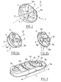
- the alternative embodiment of the present invention shown in Figures 2a and 2b comprises a movable switching element 3 which comprises a first portion 3a mounted in a ball joint on a vehicle element and a second portion 3b movable in translation along the Z axis which corresponds to substantially substantially to the axis of symmetry of the movable switching element 3.
- the first part 3a corresponds to the ball 3 described in the first embodiment and comprises projections 5a whose sides form touch zones.
- the movements of this first part 3a are identical to those described in the case of this ball joint (unstable translations and rotation).
- the second portion 3b is shaped as a disc provided with orifices for the passage of projections 5a, which are for example cylindrical outline of any base to allow the relative sliding portions 3a and 3b.
- the disk 3b can occupy by sliding two positions, one, advanced ( Figure 2a) where it masks the sides of the projections 5a, and the other, pressed, where it leaves these sides 5a protrusions released and accessible to the user .
- Figure 2a advanced
- the tactile zones 5 are inaccessible to the touch.
- the second part 3b is depressed on the first part 3a (FIG. 2b)
- the protuberances 5a which materialize the tactile zones 5 are then apparent and the displacement of the first element 3 can be effected by means of one of the protuberances 5a.
- the switching element 3 having two moving parts 3a and 3b, it allows the user to understand, easily and without having to look at the control device, which functions, "main” or “advanced” he has direct access.
- the control device of the invention comprises a base 3, a face 3a is integral with a vehicle element and the other face 3b comprises a movable pallet 3c .
- This pallet 3c is movable in translation along the length L of the base 3.
- the movable pallet 3c which acts as a switching element comprises on its surface several tactile zones materialized by protuberances each equipped with unrepresented touch recognition means.
- the pallet 3c comprises a protuberance 5a controlling the simultaneous opening and closing of the four windows of the vehicle, four protuberances 5b which control the opening of a particular pane of the vehicle and two protuberances 5c which control the orientation mirrors of the vehicle. All the aforementioned protuberances allow the user to drive the moving pallet 3c in motion.
- this second embodiment is as follows.
- the touch recognition means equipping this protrusion perceive that the protuberance is touched and the function controlled by this protuberance is activated via the activation means coupled to the touch recognition means.
- the displacement in unstable translation of the movable pallet 3c by means of the protrusion touched then allows the control of the function in question, in this case, for example, opening the windows or a window of the vehicle or adjusting the orientation of the mirrors of the vehicle.
- the control device of the present invention thus makes it possible to group together in a single control device the control of several functions of the same organ or of several members.
- the displacement of a single mobile switching element makes it possible to control various functions because of its association with means of recognition of touch equipping specific zones, each dedicated to the control of a particular function of the organ or of a part of the organ.
- the device of the invention therefore makes it possible to reduce the area occupied by the control and facilitates the control of all these functions, in particular blind, since the user has to memorize only a limited number of displacements, those of the moving element. switching. The setting of the various functions is thus facilitated and faster.
- the control of the functions being implemented by the moving element switching it is easy to modulate the number of tactile zones equipping, for example, this element according to the number of functions to be controlled.
- the manufacturing cost of the device of the invention can thus be optimized.
- the movement of the switching element is no longer limited to a switch which allows new arrangements.
Claims (13)
- Steuervorrichtung (1) mit einem beweglichen Schaltelement (3; 3a, 3b; 3c), enthaltend:- berührungssensitive Bereiche (5), die mit Berührungserkennungsmitteln ausgestattet sind,- Mittel zum Aktivieren einer ersten Funktion eines Organs bzw. eines Teils dieses Organs, die mit den Berührungserkennungsmitteln gekoppelt sind, und- Mittel, mit denen die aktivierte erste Funktion durch Verstellung des beweglichen Schaltelements (3; 3a, 3b; 3c) gesteuert werden kann, wobeizumindest einer der berührungssensitiven Bereiche einen Greifabschnitt enthält, um das bewegliche Schaltelement so zu verstellen, dass die durch Berührung des berührungssensitiven Bereichs aktivierte Funktion durch Verstellung des Schaltelements gesteuert wird, dadurch gekennzeichnet, dass die Berührungserkennungsmittel einen kapazitiven Sensor enthalten, der ebenso viele Erfassungsantennen aufweist wie zahlenmäßig berührungssensitive Bereiche vorhanden sind, wobei jede Antenne ein Kennsignal, eine Kennzeichnung bei Erfassung eines Berührungskontakts ausgibt, um diesen berührten berührungssensitiven Bereich lokalisieren zu können.
- Steuervorrichtung (1) nach Anspruch 1, dadurch gekennzeichnet, dass der Greifabschnitt einen Vorsprung enthält.
- Steuervorrichtung (1) nach Anspruch 1, dadurch gekennzeichnet, dass der Greifabschnitt einen hohl ausgeführten Teil enthält.
- Steuervorrichtung (1) nach einem der Ansprüche 1 bis 3, dadurch gekennzeichnet, dass jeder berührungssensitive Bereich einen Greifabschnitt enthält, der die Bewegungsmitnahme des beweglichen Schaltelements gestattet.
- Steuervorrichtung (1) nach einem der Ansprüche 1 bis 4, dadurch gekennzeichnet, dass sie Auswertemittel enthält, die einerseits mit dem beweglichen Schaltelement verbunden sind, um die Stellung des Schaltelements auszuwerten, und andererseits mit dem bzw. den berührungssensitiven Bereichen verbunden sind, um einen Berührungszustand bzw. Nichtberührungszustand der gesamten berührungssensitiven Bereiche zu erfassen, sowie Diskriminierungsmittel, um ein spezifisches Steuerausgangssignal in Abhängigkeit von der Stellung des beweglichen Schaltelements einerseits und von dem erfassten Zustand der berührungssensitiven Bereiche andererseits auszugeben.
- Steuervorrichtung (1) nach einem der Ansprüche 1 bis 5, dadurch gekennzeichnet, dass das bewegliche Schaltelement (3; 3a, 3b; 3c) zumindest einen berührungssensitiven Bereich (5) enthält.
- Steuervorrichtung (1) nach einem der Ansprüche 1 bis 6, dadurch gekennzeichnet, dass das bewegliche Schaltelement (3; 3a, 3b; 3c) um eine Achse (Z) drehbar und in der zur Achse (Z) normalen Ebene verschiebbar ist.
- Steuervorrichtung (1) nach Anspruch 7, dadurch gekennzeichnet, dass das bewegliche Schaltelement ein Kugelgelenk (3) enthält, das im wesentlichen symmetrisch zur Achse (Z) verläuft und an seiner Oberfläche (3a) zumindest einen berührungssensitiven Bereich (5) enthält.
- Steuervorrichtung (1) nach Anspruch 8, dadurch gekennzeichnet, dass das Schaltelement (3; 3a, 3b; 3c) zwei zueinander verschiebbare Teile (3a, 3b) enthält, wobei zumindest einer der berührungssensitiven Bereiche (5) durch gegenseitiges Verschieben der Teile (3a, 3b) für die Berührung zugänglich ist.
- Steuervorrichtung (1) nach einem der Ansprüche 1 bis 9, dadurch gekennzeichnet, dass das Schaltelement (3c) in einer Ebene verschiebbar ist.
- Steuervorrichtung (1) nach Anspruch 10, dadurch gekennzeichnet, dass sie einen Sockel enthält, in welchem das Schaltelement gleitet, der eine Platte (3c) enthält, wobei die Platte (3c) zumindest einen berührungssensitiven Bereich aufweist.
- Steuervorrichtung (1) nach einem der Ansprüche 1 bis 11, dadurch gekennzeichnet, dass sie so ausgebildet ist, dass sie das Öffnen und Schließen von zumindest zwei zu öffnenden Teilen eines Kraftfahrzeugs steuern kann.
- Steuervorrichtung (1) nach einem der Ansprüche 1 bis 12, dadurch gekennzeichnet, dass sie so ausgebildet ist, dass sie die Anlenkung der verschiedenen Teile eines Kraftfahrzeugsitzes steuern kann.
Applications Claiming Priority (2)
| Application Number | Priority Date | Filing Date | Title |
|---|---|---|---|
| FR0214647 | 2002-11-22 | ||
| FR0214647A FR2847712B1 (fr) | 2002-11-22 | 2002-11-22 | Procede de commande d'au moins deux fonctions d'un organe et/ou d'au moins deux parties distinctes d'un organe et dispositif de commande |
Publications (2)
| Publication Number | Publication Date |
|---|---|
| EP1424710A1 EP1424710A1 (de) | 2004-06-02 |
| EP1424710B1 true EP1424710B1 (de) | 2006-05-17 |
Family
ID=32241517
Family Applications (1)
| Application Number | Title | Priority Date | Filing Date |
|---|---|---|---|
| EP03104333A Expired - Lifetime EP1424710B1 (de) | 2002-11-22 | 2003-11-24 | Steuervorrichtung für wenigstens zwei Funktionen eines Elementes und/oder wenigstens zwei verschiedener Elementteile |
Country Status (4)
| Country | Link |
|---|---|
| EP (1) | EP1424710B1 (de) |
| AT (1) | ATE326766T1 (de) |
| DE (1) | DE60305276T2 (de) |
| FR (1) | FR2847712B1 (de) |
Cited By (2)
| Publication number | Priority date | Publication date | Assignee | Title |
|---|---|---|---|---|
| DE102006028462A1 (de) * | 2006-06-21 | 2008-01-03 | Audi Ag | Schalter zur Verstellung eines Fahrzeugsitzes |
| EP1973131A1 (de) | 2007-03-17 | 2008-09-24 | Wilfried Beck | Mehrwegschalter, insbesondere für Blinde |
Families Citing this family (7)
| Publication number | Priority date | Publication date | Assignee | Title |
|---|---|---|---|---|
| FR2880145B1 (fr) | 2004-12-23 | 2008-08-08 | Peugeot Citroen Automobiles Sa | Organe de commutation et dispositif de commande comportant un tel organe |
| JP4560817B2 (ja) * | 2005-04-28 | 2010-10-13 | 東洋電装株式会社 | 車両用パワーシートの操作スイッチ |
| DE102005046328A1 (de) * | 2005-09-28 | 2007-04-05 | Daimlerchrysler Ag | Bedieneinrichtung |
| ES2317778B2 (es) * | 2007-04-03 | 2010-06-18 | Maier, S.Coop | Panel de control localizado en el reposabrazos de una puerta de un vehiculo. |
| FR2992075B1 (fr) * | 2012-06-14 | 2015-06-05 | Alphaui | Touches pour clavier dorsal. |
| EP3242307B1 (de) | 2016-05-03 | 2020-10-28 | Electrolux Appliances Aktiebolag | Schaltelement für eine steuerungsvorrichtung |
| FR3104752B1 (fr) * | 2019-12-12 | 2022-07-22 | Dav | Dispositif de commande électrique pour la commande d’au moins une fonction d’un organe de véhicule automobile |
Family Cites Families (9)
| Publication number | Priority date | Publication date | Assignee | Title |
|---|---|---|---|---|
| JPS587556Y2 (ja) * | 1978-11-08 | 1983-02-09 | 日産自動車株式会社 | 絵表示スイツチ |
| DE3129422A1 (de) * | 1981-07-25 | 1983-02-10 | Licentia Gmbh | Netzabhaengiger elektronischer tastschalter |
| DE3910977A1 (de) * | 1989-04-05 | 1990-10-11 | Harms & Wende Gmbh U Co Kg | Komputereingabevorrichtung |
| US5541622A (en) * | 1990-07-24 | 1996-07-30 | Incontrol Solutions, Inc. | Miniature isometric joystick |
| FR2737686B1 (fr) * | 1995-08-11 | 1997-10-17 | Faure Bertrand Equipements Sa | Dispositif de commande pour siege de vehicule |
| US5864105A (en) * | 1996-12-30 | 1999-01-26 | Trw Inc. | Method and apparatus for controlling an adjustable device |
| DE19936257A1 (de) * | 1999-07-31 | 2001-02-01 | Georg Geiser | Berührungssensitiver Mehrfachdrehknopf für adaptierbares Dialogverfahren |
| DE10060396A1 (de) * | 2000-12-05 | 2002-06-13 | Volkswagen Ag | Bedienschalter für Aggregate in einem Kraftfahrzeug |
| JP2003297172A (ja) * | 2002-03-29 | 2003-10-17 | Matsushita Electric Ind Co Ltd | 電子機器 |
-
2002
- 2002-11-22 FR FR0214647A patent/FR2847712B1/fr not_active Expired - Fee Related
-
2003
- 2003-11-24 DE DE60305276T patent/DE60305276T2/de not_active Expired - Lifetime
- 2003-11-24 AT AT03104333T patent/ATE326766T1/de not_active IP Right Cessation
- 2003-11-24 EP EP03104333A patent/EP1424710B1/de not_active Expired - Lifetime
Cited By (3)
| Publication number | Priority date | Publication date | Assignee | Title |
|---|---|---|---|---|
| DE102006028462A1 (de) * | 2006-06-21 | 2008-01-03 | Audi Ag | Schalter zur Verstellung eines Fahrzeugsitzes |
| DE102006028462B4 (de) * | 2006-06-21 | 2010-06-02 | Audi Ag | Schalter zur Verstellung eines Fahrzeugsitzes |
| EP1973131A1 (de) | 2007-03-17 | 2008-09-24 | Wilfried Beck | Mehrwegschalter, insbesondere für Blinde |
Also Published As
| Publication number | Publication date |
|---|---|
| ATE326766T1 (de) | 2006-06-15 |
| DE60305276T2 (de) | 2007-05-03 |
| FR2847712B1 (fr) | 2008-08-22 |
| EP1424710A1 (de) | 2004-06-02 |
| FR2847712A1 (fr) | 2004-05-28 |
| DE60305276D1 (de) | 2006-06-22 |
Similar Documents
| Publication | Publication Date | Title |
|---|---|---|
| EP2165250B1 (de) | Elektrische steuereinrichtung | |
| EP2054904B1 (de) | Steuermodul insbesondere für ein automotive-fahrzeugmodul | |
| EP1424710B1 (de) | Steuervorrichtung für wenigstens zwei Funktionen eines Elementes und/oder wenigstens zwei verschiedener Elementteile | |
| EP3201713B1 (de) | Steuerungsvorrichtung mit knauf | |
| EP3519233A1 (de) | Schnittstelle für kraftfahrzeug und steuerungsverfahren | |
| EP3436302A1 (de) | Schnittstelle für ein kraftfahrzeug | |
| EP2891045B1 (de) | Steuermodul mit einer berührungsempfindlichen oberfläche | |
| WO2010046372A1 (fr) | Bouton de commande multifonction | |
| EP2151054A1 (de) | Berührungssteuereinrichtung mit haptischer rückmeldung | |
| WO2018060388A1 (fr) | Interface pour véhicule automobile et procédé d'éclairage | |
| EP3519234B1 (de) | Schnittstelle für ein kraftfahrzeug und verfahren zur erzeugung einer haptischen rückmeldung | |
| FR3056473B1 (fr) | Interface pour vehicule automobile et procede de commande | |
| EP3795406B1 (de) | Fahrzeugteil mit benutzerschnittstelle | |
| FR2825832A1 (fr) | Dispositif de commande comportant au moins une surface sensible au toucher | |
| EP3827455B1 (de) | Steuerungsmodul mit kippschaltern | |
| EP3519230B1 (de) | Schnittstelle für ein kraftfahrzeug | |
| EP3393840B1 (de) | Fahrzeuglenkrad mit berührungsempfindlicher oberfläche | |
| EP1562782A2 (de) | Steuerungseinrichtung für mindestens zwei funktionen einer vorrichtung | |
| FR2841351A1 (fr) | Unite de manoeuvre pour composants de vehicule automobile | |
| FR2833387A1 (fr) | Procede de gestion et d'exploitation d'un ensemble d'organes de consigne d'un vehicule automobile, incluant l'emission d'un signal sonore | |
| EP3400503B1 (de) | Steuerelement | |
| FR3095532A1 (fr) | Interface pour véhicule automobile | |
| EP4301618A1 (de) | Schnittstelle für ein kraftfahrzeug und verfahren zum steuern einer kraftfahrzeugkomponente | |
| FR3031600A1 (fr) | Dispositif de commande tactile |
Legal Events
| Date | Code | Title | Description |
|---|---|---|---|
| PUAI | Public reference made under article 153(3) epc to a published international application that has entered the european phase |
Free format text: ORIGINAL CODE: 0009012 |
|
| AK | Designated contracting states |
Kind code of ref document: A1 Designated state(s): AT BE BG CH CY CZ DE DK EE ES FI FR GB GR HU IE IT LI LU MC NL PT RO SE SI SK TR |
|
| AX | Request for extension of the european patent |
Extension state: AL LT LV MK |
|
| 17P | Request for examination filed |
Effective date: 20041123 |
|
| AKX | Designation fees paid |
Designated state(s): AT BE BG CH CY CZ DE DK EE ES FI FR GB GR HU IE IT LI LU MC NL PT RO SE SI SK TR |
|
| 17Q | First examination report despatched |
Effective date: 20050329 |
|
| GRAP | Despatch of communication of intention to grant a patent |
Free format text: ORIGINAL CODE: EPIDOSNIGR1 |
|
| RIN1 | Information on inventor provided before grant (corrected) |
Inventor name: LEBRETON, ETIENNEC/O DAV Inventor name: TISSOT, JEAN MARCC/O DAV |
|
| GRAS | Grant fee paid |
Free format text: ORIGINAL CODE: EPIDOSNIGR3 |
|
| GRAA | (expected) grant |
Free format text: ORIGINAL CODE: 0009210 |
|
| AK | Designated contracting states |
Kind code of ref document: B1 Designated state(s): AT BE BG CH CY CZ DE DK EE ES FI FR GB GR HU IE IT LI LU MC NL PT RO SE SI SK TR |
|
| PG25 | Lapsed in a contracting state [announced via postgrant information from national office to epo] |
Ref country code: IT Free format text: LAPSE BECAUSE OF FAILURE TO SUBMIT A TRANSLATION OF THE DESCRIPTION OR TO PAY THE FEE WITHIN THE PRESCRIBED TIME-LIMIT;WARNING: LAPSES OF ITALIAN PATENTS WITH EFFECTIVE DATE BEFORE 2007 MAY HAVE OCCURRED AT ANY TIME BEFORE 2007. THE CORRECT EFFECTIVE DATE MAY BE DIFFERENT FROM THE ONE RECORDED. Effective date: 20060517 Ref country code: AT Free format text: LAPSE BECAUSE OF FAILURE TO SUBMIT A TRANSLATION OF THE DESCRIPTION OR TO PAY THE FEE WITHIN THE PRESCRIBED TIME-LIMIT Effective date: 20060517 Ref country code: CZ Free format text: LAPSE BECAUSE OF FAILURE TO SUBMIT A TRANSLATION OF THE DESCRIPTION OR TO PAY THE FEE WITHIN THE PRESCRIBED TIME-LIMIT Effective date: 20060517 Ref country code: NL Free format text: LAPSE BECAUSE OF FAILURE TO SUBMIT A TRANSLATION OF THE DESCRIPTION OR TO PAY THE FEE WITHIN THE PRESCRIBED TIME-LIMIT Effective date: 20060517 Ref country code: IE Free format text: LAPSE BECAUSE OF FAILURE TO SUBMIT A TRANSLATION OF THE DESCRIPTION OR TO PAY THE FEE WITHIN THE PRESCRIBED TIME-LIMIT Effective date: 20060517 Ref country code: SK Free format text: LAPSE BECAUSE OF FAILURE TO SUBMIT A TRANSLATION OF THE DESCRIPTION OR TO PAY THE FEE WITHIN THE PRESCRIBED TIME-LIMIT Effective date: 20060517 Ref country code: SI Free format text: LAPSE BECAUSE OF FAILURE TO SUBMIT A TRANSLATION OF THE DESCRIPTION OR TO PAY THE FEE WITHIN THE PRESCRIBED TIME-LIMIT Effective date: 20060517 Ref country code: FI Free format text: LAPSE BECAUSE OF FAILURE TO SUBMIT A TRANSLATION OF THE DESCRIPTION OR TO PAY THE FEE WITHIN THE PRESCRIBED TIME-LIMIT Effective date: 20060517 Ref country code: RO Free format text: LAPSE BECAUSE OF FAILURE TO SUBMIT A TRANSLATION OF THE DESCRIPTION OR TO PAY THE FEE WITHIN THE PRESCRIBED TIME-LIMIT Effective date: 20060517 |
|
| REG | Reference to a national code |
Ref country code: GB Ref legal event code: FG4D Free format text: NOT ENGLISH |
|
| REG | Reference to a national code |
Ref country code: CH Ref legal event code: EP |
|
| REG | Reference to a national code |
Ref country code: IE Ref legal event code: FG4D Free format text: LANGUAGE OF EP DOCUMENT: FRENCH |
|
| REF | Corresponds to: |
Ref document number: 60305276 Country of ref document: DE Date of ref document: 20060622 Kind code of ref document: P |
|
| PG25 | Lapsed in a contracting state [announced via postgrant information from national office to epo] |
Ref country code: DK Free format text: LAPSE BECAUSE OF FAILURE TO SUBMIT A TRANSLATION OF THE DESCRIPTION OR TO PAY THE FEE WITHIN THE PRESCRIBED TIME-LIMIT Effective date: 20060817 |
|
| PG25 | Lapsed in a contracting state [announced via postgrant information from national office to epo] |
Ref country code: ES Free format text: LAPSE BECAUSE OF FAILURE TO SUBMIT A TRANSLATION OF THE DESCRIPTION OR TO PAY THE FEE WITHIN THE PRESCRIBED TIME-LIMIT Effective date: 20060828 |
|
| REG | Reference to a national code |
Ref country code: SE Ref legal event code: TRGR |
|
| GBT | Gb: translation of ep patent filed (gb section 77(6)(a)/1977) |
Effective date: 20060901 |
|
| PG25 | Lapsed in a contracting state [announced via postgrant information from national office to epo] |
Ref country code: PT Free format text: LAPSE BECAUSE OF FAILURE TO SUBMIT A TRANSLATION OF THE DESCRIPTION OR TO PAY THE FEE WITHIN THE PRESCRIBED TIME-LIMIT Effective date: 20061017 |
|
| NLV1 | Nl: lapsed or annulled due to failure to fulfill the requirements of art. 29p and 29m of the patents act | ||
| PG25 | Lapsed in a contracting state [announced via postgrant information from national office to epo] |
Ref country code: MC Free format text: LAPSE BECAUSE OF NON-PAYMENT OF DUE FEES Effective date: 20061130 Ref country code: BE Free format text: LAPSE BECAUSE OF NON-PAYMENT OF DUE FEES Effective date: 20061130 |
|
| REG | Reference to a national code |
Ref country code: IE Ref legal event code: FD4D |
|
| PLBE | No opposition filed within time limit |
Free format text: ORIGINAL CODE: 0009261 |
|
| STAA | Information on the status of an ep patent application or granted ep patent |
Free format text: STATUS: NO OPPOSITION FILED WITHIN TIME LIMIT |
|
| 26N | No opposition filed |
Effective date: 20070220 |
|
| BERE | Be: lapsed |
Owner name: DAV Effective date: 20061130 |
|
| PG25 | Lapsed in a contracting state [announced via postgrant information from national office to epo] |
Ref country code: GR Free format text: LAPSE BECAUSE OF FAILURE TO SUBMIT A TRANSLATION OF THE DESCRIPTION OR TO PAY THE FEE WITHIN THE PRESCRIBED TIME-LIMIT Effective date: 20060818 |
|
| PG25 | Lapsed in a contracting state [announced via postgrant information from national office to epo] |
Ref country code: EE Free format text: LAPSE BECAUSE OF FAILURE TO SUBMIT A TRANSLATION OF THE DESCRIPTION OR TO PAY THE FEE WITHIN THE PRESCRIBED TIME-LIMIT Effective date: 20060517 Ref country code: BG Free format text: LAPSE BECAUSE OF FAILURE TO SUBMIT A TRANSLATION OF THE DESCRIPTION OR TO PAY THE FEE WITHIN THE PRESCRIBED TIME-LIMIT Effective date: 20060817 |
|
| PG25 | Lapsed in a contracting state [announced via postgrant information from national office to epo] |
Ref country code: LU Free format text: LAPSE BECAUSE OF NON-PAYMENT OF DUE FEES Effective date: 20061124 Ref country code: LI Free format text: LAPSE BECAUSE OF NON-PAYMENT OF DUE FEES Effective date: 20071130 Ref country code: HU Free format text: LAPSE BECAUSE OF FAILURE TO SUBMIT A TRANSLATION OF THE DESCRIPTION OR TO PAY THE FEE WITHIN THE PRESCRIBED TIME-LIMIT Effective date: 20061118 Ref country code: TR Free format text: LAPSE BECAUSE OF FAILURE TO SUBMIT A TRANSLATION OF THE DESCRIPTION OR TO PAY THE FEE WITHIN THE PRESCRIBED TIME-LIMIT Effective date: 20060517 Ref country code: CH Free format text: LAPSE BECAUSE OF NON-PAYMENT OF DUE FEES Effective date: 20071130 |
|
| REG | Reference to a national code |
Ref country code: CH Ref legal event code: PL |
|
| PG25 | Lapsed in a contracting state [announced via postgrant information from national office to epo] |
Ref country code: CY Free format text: LAPSE BECAUSE OF FAILURE TO SUBMIT A TRANSLATION OF THE DESCRIPTION OR TO PAY THE FEE WITHIN THE PRESCRIBED TIME-LIMIT Effective date: 20060517 |
|
| PGFP | Annual fee paid to national office [announced via postgrant information from national office to epo] |
Ref country code: GB Payment date: 20081107 Year of fee payment: 6 |
|
| GBPC | Gb: european patent ceased through non-payment of renewal fee |
Effective date: 20091124 |
|
| PG25 | Lapsed in a contracting state [announced via postgrant information from national office to epo] |
Ref country code: GB Free format text: LAPSE BECAUSE OF NON-PAYMENT OF DUE FEES Effective date: 20091124 |
|
| REG | Reference to a national code |
Ref country code: FR Ref legal event code: PLFP Year of fee payment: 13 |
|
| REG | Reference to a national code |
Ref country code: FR Ref legal event code: PLFP Year of fee payment: 14 |
|
| PGFP | Annual fee paid to national office [announced via postgrant information from national office to epo] |
Ref country code: SE Payment date: 20161118 Year of fee payment: 14 Ref country code: IT Payment date: 20161116 Year of fee payment: 14 |
|
| REG | Reference to a national code |
Ref country code: FR Ref legal event code: PLFP Year of fee payment: 15 |
|
| REG | Reference to a national code |
Ref country code: SE Ref legal event code: EUG |
|
| PG25 | Lapsed in a contracting state [announced via postgrant information from national office to epo] |
Ref country code: SE Free format text: LAPSE BECAUSE OF NON-PAYMENT OF DUE FEES Effective date: 20171125 |
|
| PG25 | Lapsed in a contracting state [announced via postgrant information from national office to epo] |
Ref country code: IT Free format text: LAPSE BECAUSE OF NON-PAYMENT OF DUE FEES Effective date: 20171124 |
|
| PGFP | Annual fee paid to national office [announced via postgrant information from national office to epo] |
Ref country code: FR Payment date: 20221122 Year of fee payment: 20 Ref country code: DE Payment date: 20221114 Year of fee payment: 20 |
|
| P01 | Opt-out of the competence of the unified patent court (upc) registered |
Effective date: 20230528 |
|
| REG | Reference to a national code |
Ref country code: DE Ref legal event code: R071 Ref document number: 60305276 Country of ref document: DE |