EP1424710B1 - Control device for at least two functions of an element and/or at least two different parts of an element - Google Patents
Control device for at least two functions of an element and/or at least two different parts of an element Download PDFInfo
- Publication number
- EP1424710B1 EP1424710B1 EP03104333A EP03104333A EP1424710B1 EP 1424710 B1 EP1424710 B1 EP 1424710B1 EP 03104333 A EP03104333 A EP 03104333A EP 03104333 A EP03104333 A EP 03104333A EP 1424710 B1 EP1424710 B1 EP 1424710B1
- Authority
- EP
- European Patent Office
- Prior art keywords
- switching element
- control device
- tactile
- control
- function
- Prior art date
- Legal status (The legal status is an assumption and is not a legal conclusion. Google has not performed a legal analysis and makes no representation as to the accuracy of the status listed.)
- Expired - Lifetime
Links
- 238000013519 translation Methods 0.000 claims abstract description 16
- 230000033001 locomotion Effects 0.000 claims description 12
- 238000001514 detection method Methods 0.000 claims description 5
- 230000003213 activating effect Effects 0.000 claims description 3
- 238000011156 evaluation Methods 0.000 claims description 2
- 230000003287 optical effect Effects 0.000 abstract description 3
- 230000000694 effects Effects 0.000 abstract 1
- 210000000056 organ Anatomy 0.000 description 12
- 230000014616 translation Effects 0.000 description 11
- 238000006073 displacement reaction Methods 0.000 description 8
- 230000009471 action Effects 0.000 description 6
- 238000000034 method Methods 0.000 description 5
- 230000008859 change Effects 0.000 description 4
- 230000004913 activation Effects 0.000 description 3
- 230000003155 kinesthetic effect Effects 0.000 description 3
- 239000000463 material Substances 0.000 description 3
- 238000013459 approach Methods 0.000 description 1
- 239000003990 capacitor Substances 0.000 description 1
- 230000000994 depressogenic effect Effects 0.000 description 1
- 238000010586 diagram Methods 0.000 description 1
- 238000001914 filtration Methods 0.000 description 1
- 230000006872 improvement Effects 0.000 description 1
- 238000004519 manufacturing process Methods 0.000 description 1
- 239000003973 paint Substances 0.000 description 1
- 210000004417 patella Anatomy 0.000 description 1
- 238000012545 processing Methods 0.000 description 1
- 230000011664 signaling Effects 0.000 description 1
- 238000012360 testing method Methods 0.000 description 1
- 238000010257 thawing Methods 0.000 description 1
Images
Classifications
-
- G—PHYSICS
- G05—CONTROLLING; REGULATING
- G05G—CONTROL DEVICES OR SYSTEMS INSOFAR AS CHARACTERISED BY MECHANICAL FEATURES ONLY
- G05G5/00—Means for preventing, limiting or returning the movements of parts of a control mechanism, e.g. locking controlling member
- G05G5/06—Means for preventing, limiting or returning the movements of parts of a control mechanism, e.g. locking controlling member for holding members in one or a limited number of definite positions only
-
- B—PERFORMING OPERATIONS; TRANSPORTING
- B60—VEHICLES IN GENERAL
- B60N—SEATS SPECIALLY ADAPTED FOR VEHICLES; VEHICLE PASSENGER ACCOMMODATION NOT OTHERWISE PROVIDED FOR
- B60N2/00—Seats specially adapted for vehicles; Arrangement or mounting of seats in vehicles
- B60N2/02—Seats specially adapted for vehicles; Arrangement or mounting of seats in vehicles the seat or part thereof being movable, e.g. adjustable
- B60N2/0224—Non-manual adjustments, e.g. with electrical operation
- B60N2/0226—User interfaces specially adapted for seat adjustment
- B60N2/0228—Hand-activated mechanical switches
-
- G—PHYSICS
- G05—CONTROLLING; REGULATING
- G05G—CONTROL DEVICES OR SYSTEMS INSOFAR AS CHARACTERISED BY MECHANICAL FEATURES ONLY
- G05G13/00—Manually-actuated control mechanisms provided with two or more controlling members and also two or more controlled members
- G05G13/02—Manually-actuated control mechanisms provided with two or more controlling members and also two or more controlled members with separate controlling members for preselection and shifting of controlled members
-
- G—PHYSICS
- G05—CONTROLLING; REGULATING
- G05G—CONTROL DEVICES OR SYSTEMS INSOFAR AS CHARACTERISED BY MECHANICAL FEATURES ONLY
- G05G9/00—Manually-actuated control mechanisms provided with one single controlling member co-operating with two or more controlled members, e.g. selectively, simultaneously
- G05G9/02—Manually-actuated control mechanisms provided with one single controlling member co-operating with two or more controlled members, e.g. selectively, simultaneously the controlling member being movable in different independent ways, movement in each individual way actuating one controlled member only
- G05G9/04—Manually-actuated control mechanisms provided with one single controlling member co-operating with two or more controlled members, e.g. selectively, simultaneously the controlling member being movable in different independent ways, movement in each individual way actuating one controlled member only in which movement in two or more ways can occur simultaneously
-
- H—ELECTRICITY
- H01—ELECTRIC ELEMENTS
- H01H—ELECTRIC SWITCHES; RELAYS; SELECTORS; EMERGENCY PROTECTIVE DEVICES
- H01H15/00—Switches having rectilinearly-movable operating part or parts adapted for actuation in opposite directions, e.g. slide switch
- H01H15/02—Details
- H01H15/06—Movable parts; Contacts mounted thereon
- H01H15/10—Operating parts
-
- H—ELECTRICITY
- H01—ELECTRIC ELEMENTS
- H01H—ELECTRIC SWITCHES; RELAYS; SELECTORS; EMERGENCY PROTECTIVE DEVICES
- H01H25/00—Switches with compound movement of handle or other operating part
-
- H—ELECTRICITY
- H01—ELECTRIC ELEMENTS
- H01H—ELECTRIC SWITCHES; RELAYS; SELECTORS; EMERGENCY PROTECTIVE DEVICES
- H01H25/00—Switches with compound movement of handle or other operating part
- H01H25/04—Operating part movable angularly in more than one plane, e.g. joystick
- H01H25/041—Operating part movable angularly in more than one plane, e.g. joystick having a generally flat operating member depressible at different locations to operate different controls
-
- H—ELECTRICITY
- H01—ELECTRIC ELEMENTS
- H01H—ELECTRIC SWITCHES; RELAYS; SELECTORS; EMERGENCY PROTECTIVE DEVICES
- H01H25/00—Switches with compound movement of handle or other operating part
- H01H25/06—Operating part movable both angularly and rectilinearly, the rectilinear movement being along the axis of angular movement
-
- H—ELECTRICITY
- H01—ELECTRIC ELEMENTS
- H01H—ELECTRIC SWITCHES; RELAYS; SELECTORS; EMERGENCY PROTECTIVE DEVICES
- H01H3/00—Mechanisms for operating contacts
- H01H3/02—Operating parts, i.e. for operating driving mechanism by a mechanical force external to the switch
- H01H2003/0293—Operating parts, i.e. for operating driving mechanism by a mechanical force external to the switch with an integrated touch switch
-
- H—ELECTRICITY
- H01—ELECTRIC ELEMENTS
- H01H—ELECTRIC SWITCHES; RELAYS; SELECTORS; EMERGENCY PROTECTIVE DEVICES
- H01H2300/00—Orthogonal indexing scheme relating to electric switches, relays, selectors or emergency protective devices covered by H01H
- H01H2300/008—Application power seats
Definitions
- the present invention relates to a method for controlling at least two functions of a member and / or at least two distinct parts of a member and a control device for carrying out this method. More particularly, the present invention relates to a method and a device for controlling the position and articulation of the different parts of a motor vehicle seat and a device for controlling the opening and closing of at least one opening of a motor vehicle.
- the object of the present invention is to provide a device for controlling at least two functions of an organ and / or at least two parts of an organ that overcomes all or part of the aforementioned drawbacks.
- the device comprising at least one touch zone equipped with touch recognition means, a first tactile action is exerted on a first touch zone of the control device so as to activate a first function of the touch device. member or a first part of this member and moving the movable switching element is controlled to control this first function; a second tactile action is then performed either on a second touch zone or on a zone of the mobile switching element not equipped with touch recognition means so as to activate a second function and the moving element is driven in motion to control this second function.
- the term "tactile action” refers to any action of gripping, touching or touching exerted by the user on the touch zone.
- the touch recognition means are not limited. They may be, for example, resistive type, optical capacitive or other.
- the term "function" denotes, for example, the movement, the change of state of an organ or part of this organ or the activation of another organ or device.
- member means any mechanical part or set of mechanical parts that can be controlled, in particular separately.
- the method of the invention thus makes it possible to control two functions of a member and / or the function of two distinct parts of the member by means of a single and mobile switching element, the touch recognition means making it possible to choose the function that must be activated before it can be ordered.
- the first function can also be directly controlled by the switching element, without having to be activated beforehand; the other or the other functions, on the other hand, must be activated by the touch recognition means before they can be controlled by moving the switching element.
- the present invention also relates to a control device comprising a movable switching element which, typically comprises at least one tactile zone equipped with touch recognition means, means for activating a function of the organ or a device. part of this member coupled to the touch recognition means and means for controlling the activated function by moving the movable switching element.
- a control device comprising a movable switching element which, typically comprises at least one tactile zone equipped with touch recognition means, means for activating a function of the organ or a device. part of this member coupled to the touch recognition means and means for controlling the activated function by moving the movable switching element.
- the arrangement of the tactile zones is not limited according to the invention.
- the mobile switching element comprises at least one tactile zone which makes it possible to facilitate the use of the device of the invention, the first tactile action and the moving drive of the mobile switching element being able to be put into operation. almost simultaneously and instinctively.
- the movement of the mobile switching element is not limited according to the invention.
- the switching element is rotatable about an axis and in translation in the plane normal to said axis.
- the mobile switching element may thus comprise a ball substantially symmetrical with respect to the axis of rotation and which has at least one touch zone on its surface.
- the mobile switching element comprises two parts movable in translation relative to one another, at least one touch zone being made accessible to the touch by translation of the parts relative to one another.
- the switching element is movable in translation in a plane.
- the device of the invention may comprise, for example, a base in which slides the switching element which comprises a pallet comprising at least one touch zone.
- this zone advantageously comprises means for moving the switching element. These means are not limited according to the invention.
- It may be, for example, a non-slip material surface covering all or part of the tactile zone or one or more protuberances or recessed portions which also make it easy to locate, visually and in a tactile manner, the zone. touch.
- the device of the present invention can be used, for example, in the field of the automotive industry to control the opening and closing of at least one opening, such as, for example, a window or to control the articulation various parts of a motor vehicle seat.
- the first embodiment of the device 1 of the invention comprises a ball joint 3 (commonly called a "joystick") which acts as a mobile switching element and which makes it possible, by moving it, to control all functions.
- the ball 3 is substantially symmetrical about the Z axis and movable in unstable rotation by a few degrees about the Z axis. It is also movable in unstable translation in the plane normal to the Z axis.
- are arranged on the free surface 3a of the ball joint 3 each comprise a gripping portion, a protuberance 5a. These protuberances 5a make it possible both to locate the touch zone 5 and, as subsequently explained, to drive the switching element 3 in movement.
- the gripping portion is formed as a recessed portion.
- the tactile zones 5 are each equipped with unrepresented touch recognition means.
- the shape, number and arrangement of the protuberances 5a are not limited according to the invention.
- the number of protuberances 5a depends on the number of functions and or parts of the organ to be controlled.
- the touch recognition means comprise a capacitive sensor.
- the capacitance of a test capacitor changes as a user's hand approaches or touches the control element. When such a change in capacity is detected, it is associated with whether the user has approached or touched the control element.
- the patella is made of plastic material, preferably a material that can be coated with a paint, metallized or not. It has under its face intended to be in contact with the user or housing to receive the part (s) of the sensor for changing capacity in case of touch by a user, this part may be as example an antenna.
- each antenna generating a characteristic signal (a signature) in the event of detection of a touch contact so that one can use for the capacitive sensor a single signal processing circuit antennas and thus reduce the cost and size of the device according to the invention.
- the touch recognition means comprise an optical sensor, functioning for example on a transmission-reflection principle.
- the area of the control element intended to be touched has a reflection window of the light emitted by a light emitter to a receiver (a photodiode). Touching this detection window will change its reflection properties and thus detect the touch of a user.
- the emitted light is in the visible and the window has a characteristic shape so that the emitted light serves at the same time backlighting the control element.
- a circuit is provided for filtering this contribution to avoid untimely commands.
- a sound signaling means for the recognition of touch by a user.
- the device comprises evaluation means (not shown) connected on the one hand to the mobile switching element to evaluate the position of the switching element and on the other hand to the one or more tactile zones to detect a state , touched or not, all of said touch zones and discriminating means for delivering a specific control output signal depending on a part of the position of the mobile switching element and on the other hand of the state detected said touch zones.
- This arrangement is particularly advantageous because it allows not only that it can be controlled by touching a single function by touch zone, but to control a specific function when detecting a combination of touch zones touched.
- this first embodiment of the device of the invention will now be described, in the case of controlling the functions of a motor vehicle seat.
- the main functions of the seat are activated. That is to say that the movements of the movable member 3 control both the displacement in translation parallel to the floor of the vehicle and perpendicular to the latter of the seat and the seat backrest inclination.
- the user who sits in the seat can have a purely kinesthetic feedback, he then adjusts the seat position according to how he feels and he does not need to use his sight.
- the controlled part may vibrate or emit a sound.
- the setting of the main functions can therefore be done while driving.
- Each of the protuberances 5a controls a so-called “advanced” function of the seat.
- These “advanced functions” correspond in particular to the vertical translation of the headrest of the seat, the articulation of the seat at the lumbar vertebrae and the articulation of the front part of the seat base.
- the touch recognition means which equips it being coupled to means for activating a specific function, this function is activated.
- the feedback can be purely kinesthetic and the adjustment can be done blindly while driving.
- the aforementioned feedback may also be implemented in this case.
- the alternative embodiment of the present invention shown in Figures 2a and 2b comprises a movable switching element 3 which comprises a first portion 3a mounted in a ball joint on a vehicle element and a second portion 3b movable in translation along the Z axis which corresponds to substantially substantially to the axis of symmetry of the movable switching element 3.
- the first part 3a corresponds to the ball 3 described in the first embodiment and comprises projections 5a whose sides form touch zones.
- the movements of this first part 3a are identical to those described in the case of this ball joint (unstable translations and rotation).
- the second portion 3b is shaped as a disc provided with orifices for the passage of projections 5a, which are for example cylindrical outline of any base to allow the relative sliding portions 3a and 3b.
- the disk 3b can occupy by sliding two positions, one, advanced ( Figure 2a) where it masks the sides of the projections 5a, and the other, pressed, where it leaves these sides 5a protrusions released and accessible to the user .
- Figure 2a advanced
- the tactile zones 5 are inaccessible to the touch.
- the second part 3b is depressed on the first part 3a (FIG. 2b)
- the protuberances 5a which materialize the tactile zones 5 are then apparent and the displacement of the first element 3 can be effected by means of one of the protuberances 5a.
- the switching element 3 having two moving parts 3a and 3b, it allows the user to understand, easily and without having to look at the control device, which functions, "main” or “advanced” he has direct access.
- the control device of the invention comprises a base 3, a face 3a is integral with a vehicle element and the other face 3b comprises a movable pallet 3c .
- This pallet 3c is movable in translation along the length L of the base 3.
- the movable pallet 3c which acts as a switching element comprises on its surface several tactile zones materialized by protuberances each equipped with unrepresented touch recognition means.
- the pallet 3c comprises a protuberance 5a controlling the simultaneous opening and closing of the four windows of the vehicle, four protuberances 5b which control the opening of a particular pane of the vehicle and two protuberances 5c which control the orientation mirrors of the vehicle. All the aforementioned protuberances allow the user to drive the moving pallet 3c in motion.
- this second embodiment is as follows.
- the touch recognition means equipping this protrusion perceive that the protuberance is touched and the function controlled by this protuberance is activated via the activation means coupled to the touch recognition means.
- the displacement in unstable translation of the movable pallet 3c by means of the protrusion touched then allows the control of the function in question, in this case, for example, opening the windows or a window of the vehicle or adjusting the orientation of the mirrors of the vehicle.
- the control device of the present invention thus makes it possible to group together in a single control device the control of several functions of the same organ or of several members.
- the displacement of a single mobile switching element makes it possible to control various functions because of its association with means of recognition of touch equipping specific zones, each dedicated to the control of a particular function of the organ or of a part of the organ.
- the device of the invention therefore makes it possible to reduce the area occupied by the control and facilitates the control of all these functions, in particular blind, since the user has to memorize only a limited number of displacements, those of the moving element. switching. The setting of the various functions is thus facilitated and faster.
- the control of the functions being implemented by the moving element switching it is easy to modulate the number of tactile zones equipping, for example, this element according to the number of functions to be controlled.
- the manufacturing cost of the device of the invention can thus be optimized.
- the movement of the switching element is no longer limited to a switch which allows new arrangements.
Abstract
Description
La présente invention concerne un procédé de commande d'au moins deux fonctions d'un organe et/ou d'au moins deux parties distinctes d'un organe et un dispositif de commande permettant la mise en oeuvre de ce procédé. Plus particulièrement, la présente invention concerne un procédé et un dispositif de commande de la position et de l'articulation des différentes parties d'un siège de véhicule automobile et un dispositif de commande de l'ouverture et de la fermeture d'au moins un ouvrant de véhicule automobile.The present invention relates to a method for controlling at least two functions of a member and / or at least two distinct parts of a member and a control device for carrying out this method. More particularly, the present invention relates to a method and a device for controlling the position and articulation of the different parts of a motor vehicle seat and a device for controlling the opening and closing of at least one opening of a motor vehicle.
En général, chaque fonction d'un organe quel qu'il soit est commandée par un bouton levier ou autre spécifiquement dédié à cette fonction. Il en résulte une multiplication du nombre de boutons ou leviers de commande ce qui, notamment dans le domaine de l'automobile, peut s'avérer gênant. En effet, d'une part ces nombreux dispositifs de commande occupent une place grandissante tant sur le tableau de bord que sur les autres parties du véhicule et d'autre part, leur maniement n'est souvent pas aisé, en particulier lorsque l'utilisateur conduit. Il s'avère difficile de commander en aveugle une fonction de manière intuitive c'est-à-dire, par exemple, sans avoir à regarder l'emplacement du bouton commandant la fonction dont il a besoin. Le document DE 19936257 montre le préambule de la revendication 1.In general, each function of any organ is controlled by a lever or other button specifically dedicated to this function. This results in a multiplication of the number of buttons or control levers which, particularly in the automotive field, can be embarrassing. Indeed, firstly these many control devices occupy a growing place both on the dashboard and on other parts of the vehicle and secondly, their handling is often not easy, especially when the user leads. It is difficult to blindly control a function intuitively, that is, for example, without having to look at the location of the button controlling the function it needs. DE 19936257 shows the preamble of
Le but de la présente invention est de proposer un dispositif de commande d'au moins deux fonctions d'un organe et/ou d'au moins deux parties d'un organe qui pallient tout ou partie des inconvénients précités.The object of the present invention is to provide a device for controlling at least two functions of an organ and / or at least two parts of an organ that overcomes all or part of the aforementioned drawbacks.
Ce but est atteint au moyen d'un procédé de commande d'au moins deux fonctions d'un organe et/ou d'au moins deux parties distinctes dudit organe au moyen d'un dispositif de commande qui comporte au moins un élément commutant mobile. De manière caractéristique, selon l'invention, le dispositif comportant au moins une zone tactile équipée de moyens de reconnaissance de toucher, on exerce une première action tactile sur une première zone tactile du dispositif de commande en sorte d'activer une première fonction de l'organe ou une première partie de cet organe et on entraine en mouvement l'élément commutant mobile pour contrôler cette première fonction ; on exerce ensuite une seconde action tactile soit sur une seconde zone tactile soit sur une zone de l'élément commutant mobile non équipée de moyens de reconnaissance de toucher en sorte d'activer une seconde fonction et on entraîne en mouvement l'élément mobile pour contrôler cette seconde fonction.This object is achieved by means of a method of controlling at least two functions of a member and / or at least two distinct parts of said member by means of a control device which comprises at least one movable switching element. . Characteristically, according to the invention, the device comprising at least one touch zone equipped with touch recognition means, a first tactile action is exerted on a first touch zone of the control device so as to activate a first function of the touch device. member or a first part of this member and moving the movable switching element is controlled to control this first function; a second tactile action is then performed either on a second touch zone or on a zone of the mobile switching element not equipped with touch recognition means so as to activate a second function and the moving element is driven in motion to control this second function.
Dans le cadre de la présente invention, on désigne par le terme « action tactile » toute action de préhension, de toucher ou d'effleurement exercée par l'utilisateur sur la zone tactile.In the context of the present invention, the term "tactile action" refers to any action of gripping, touching or touching exerted by the user on the touch zone.
De même, selon l'invention, les moyens de reconnaissance de toucher ne sont pas limités. Ils peuvent être, par exemple, de type résistif, capacitif optique ou autre.Similarly, according to the invention, the touch recognition means are not limited. They may be, for example, resistive type, optical capacitive or other.
Dans le cadre de la présente invention, le terme « fonction » désigne, par exemple, le mouvement, le changement d'état d'un organe ou d'une partie de cet organe ou l'activation d'un autre organe ou dispositif.In the context of the present invention, the term "function" denotes, for example, the movement, the change of state of an organ or part of this organ or the activation of another organ or device.
De même, on entend par le terme « organe » toute pièce mécanique ou ensemble de pièces mécaniques susceptibles d'être commandées, notamment de manière séparée.Similarly, the term "member" means any mechanical part or set of mechanical parts that can be controlled, in particular separately.
Le procédé de l'invention permet donc de commander deux fonctions d'un organe et/ou la fonction de deux parties distinctes de l'organe au moyen d'un seul et même élément commutant mobile, les moyens de reconnaissance de toucher permettant de choisir la fonction qui doit être activée avant de pouvoir être commandée. La première fonction peut également être directement commandée par l'élément commutant, sans devoir être activée auparavant ; l'autre ou les autres fonctions, par contre, doivent être activées par les moyens de reconnaissance de toucher avant de pouvoir être commandées par déplacement de l'élément commutant.The method of the invention thus makes it possible to control two functions of a member and / or the function of two distinct parts of the member by means of a single and mobile switching element, the touch recognition means making it possible to choose the function that must be activated before it can be ordered. The first function can also be directly controlled by the switching element, without having to be activated beforehand; the other or the other functions, on the other hand, must be activated by the touch recognition means before they can be controlled by moving the switching element.
La présente invention concerne également un dispositif de commande comportant un élément commutant mobile qui, de manière caractéristique comporte au moins une zone tactile équipée de moyens de reconnaissance de toucher, des moyens d'activation d'une fonction de l'organe ou d'une partie de cet organe couplés aux moyens de reconnaissance de toucher et des moyens permettant de contrôler la fonction activée par déplacement de l'élément commutant mobile.The present invention also relates to a control device comprising a movable switching element which, typically comprises at least one tactile zone equipped with touch recognition means, means for activating a function of the organ or a device. part of this member coupled to the touch recognition means and means for controlling the activated function by moving the movable switching element.
La disposition des zones tactiles n'est pas limitée selon l'invention. Ainsi, il est possible selon l'invention d'exercer la première action tactile sur une zone distante de l'élément commutant. De manière avantageuse, l'élément commutant mobile comprend au moins une zone tactile ce qui permet de faciliter l'utilisation du dispositif de l'invention, la première action tactile et l'entraînement en mouvement de l'élément commutant mobile pouvant être mis en oeuvre de manière quasi simultanée et instinctive.The arrangement of the tactile zones is not limited according to the invention. Thus, it is possible according to the invention to exercise the first tactile action on a remote area of the switching element. Advantageously, the mobile switching element comprises at least one tactile zone which makes it possible to facilitate the use of the device of the invention, the first tactile action and the moving drive of the mobile switching element being able to be put into operation. almost simultaneously and instinctively.
Le mouvement de l'élément commutant mobile n'est pas limité selon l'invention. Selon un premier mode de réalisation, l'élément commutant est mobile en rotation autour d'un axe et en translation dans le plan normal audit axe.The movement of the mobile switching element is not limited according to the invention. According to a first embodiment, the switching element is rotatable about an axis and in translation in the plane normal to said axis.
L'élément commutant mobile peut ainsi comprendre une rotule sensiblement symétrique par rapport à l'axe de rotation et qui comporte à sa surface au moins une zone tactile.The mobile switching element may thus comprise a ball substantially symmetrical with respect to the axis of rotation and which has at least one touch zone on its surface.
Selon une variante, l'élément commutant mobile comprend deux parties mobiles en translation l'une par rapport à l'autre, au moins une zone tactile étant rendue accessible au toucher par translation des parties l'une par rapport à l'autre.According to one variant, the mobile switching element comprises two parts movable in translation relative to one another, at least one touch zone being made accessible to the touch by translation of the parts relative to one another.
Selon un second mode de réalisation, l'élément commutant est mobile en translation dans un plan.According to a second embodiment, the switching element is movable in translation in a plane.
Selon ce second mode de réalisation, le dispositif de l'invention peut comprendre, par exemple, un socle dans lequel coulisse l'élément commutant qui comporte une palette comportant au moins une zone tactile.According to this second embodiment, the device of the invention may comprise, for example, a base in which slides the switching element which comprises a pallet comprising at least one touch zone.
Lorsque au moins une des zones tactiles est disposée sur l'élément commutant, cette zone comporte, de manière avantageuse des moyens pour entraîner en mouvement l'élément commutant. Ces moyens ne sont pas limités selon l'invention.When at least one of the touch zones is disposed on the switching element, this zone advantageously comprises means for moving the switching element. These means are not limited according to the invention.
Il peut s'agir par exemple, d'une surface en matériau anti dérapant recouvrant tout ou partie de la zone tactile ou d'une ou plusieurs protubérances ou parties en creux qui permettent également de localiser facilement, visuellement et de manière tactile, la zone tactile.It may be, for example, a non-slip material surface covering all or part of the tactile zone or one or more protuberances or recessed portions which also make it easy to locate, visually and in a tactile manner, the zone. touch.
Le dispositif de la présente invention peut être utilisé, par exemple, dans le domaine de l'industrie automobile pour commander l'ouverture et la fermeture d'au moins un ouvrant, tel que, par exemple, une vitre ou pour commander l'articulation des diverses parties d'un siège de véhicule automobile.The device of the present invention can be used, for example, in the field of the automotive industry to control the opening and closing of at least one opening, such as, for example, a window or to control the articulation various parts of a motor vehicle seat.
La présente invention, ses caractéristiques et les divers avantages qu'elle procure apparaîtront mieux à la lecture de la description qui suit de deux modes de réalisation particuliers de la présente invention et qui fait référence aux dessins annexés sur lesquels :
- la figure 1 représente une vue en perspective d'un premier mode de réalisation du dispositif de la présente invention ;
- les figures 2a et 2b représentent une vue en perspective de deux états d'une variante de réalisation du premier mode de réalisation du dispositif de la présente invention représenté sur la figure 1 ; et
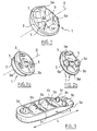
- la figure 3 représente une vue en perspective d'un second mode de réalisation du dispositif de la présente invention.
- Figure 1 shows a perspective view of a first embodiment of the device of the present invention;
- Figures 2a and 2b show a perspective view of two states of an alternative embodiment of the first embodiment of the device of the present invention shown in Figure 1; and
- Figure 3 shows a perspective view of a second embodiment of the device of the present invention.
En référence à la figure 1, le premier mode de réalisation du dispositif 1 de l'invention comporte une rotule 3 (couramment appelée "joystick") qui fait office d'élément commutant mobile et qui permet, par son déplacement, de contrôler toutes les fonctions. La rotule 3 est sensiblement symétrique par rapport à l'axe Z et mobile en rotation instable de quelques degrés autour de l'axe Z. Elle est également mobile en translation instable dans le plan normal à l'axe Z. Les zones tactiles 5 qui sont disposées sur la surface libre 3a de la rotule 3 comportent chacune une partie de préhension, une protubérance 5a. Ces protubérances 5a permettent à la fois de localiser la zone tactile 5 et comme ultérieurement expliqué, d'entraîner en mouvement l'élément commutant 3.With reference to FIG. 1, the first embodiment of the
En variante non représentée, la partie de préhension est réalisée sous forme d'une partie en creux.In variant not shown, the gripping portion is formed as a recessed portion.
Les zones tactiles 5 sont chacune équipées de moyens de reconnaissance de toucher non représentés. La forme, le nombre et la disposition des protubérances 5a ne sont pas limités selon l'invention. Le nombre de protubérances 5a dépend du nombre de fonctions et ou de parties de l'organe à commander.The
A titre d'exemple, les moyens de reconnaissance de toucher comportent un capteur capacitif. Dans ce genre de capteur, la capacité d'un condensateur de test change lorsqu'une main d'un utilisateur s'approche ou touche de l'élément de commande. Lorsqu'un tel changement de la capacité est détecté, il est associé au fait que l'utilisateur s'est approché ou a touché l'élément de commande.For example, the touch recognition means comprise a capacitive sensor. In this type of sensor, the capacitance of a test capacitor changes as a user's hand approaches or touches the control element. When such a change in capacity is detected, it is associated with whether the user has approached or touched the control element.
Selon un perfectionnement, la rotule est réalisée en matière plastique, préférentiellement une matière pouvant être revêtu d'une peinture, métallisée ou non. Elle présente sous sa face destinée à être en contact avec l'utilisateur un ou des logements pour recevoir la ou les partie (s) du capteur destiné à changer de capacité en cas de toucher par un utilisateur, cette partie pouvant être à titre d'exemple une antenne.According to an improvement, the patella is made of plastic material, preferably a material that can be coated with a paint, metallized or not. It has under its face intended to be in contact with the user or housing to receive the part (s) of the sensor for changing capacity in case of touch by a user, this part may be as example an antenna.
Par ailleurs, on peut prévoir avantageusement un seul capteur capacitif présentant autant d'antennes de détection que de nombre de zones tactiles, chaque antenne générant un signal caractéristique (une signature) en cas de détection d'un contact tactile de sorte que l'on peut utiliser pour le capteur capacitif un seul circuit de traitement des signaux des antennes et ainsi réduire le coût et l'encombrement du dispositif selon l'invention.Furthermore, it is advantageous to provide a single capacitive sensor having as many detection antennas as there are a number of touch zones, each antenna generating a characteristic signal (a signature) in the event of detection of a touch contact so that one can use for the capacitive sensor a single signal processing circuit antennas and thus reduce the cost and size of the device according to the invention.
En variante, les moyens de reconnaissance de toucher comportent un capteur optique, fonctionnant par exemple sur un principe émission - réflexion. De préférence, la zone de l'élément de commande destiné à être touchée présente une fenêtre de réflexion de la lumière émis par un émetteur de lumière vers un récepteur (une photodiode). Le fait de toucher cette fenêtre de détection va modifier ses propriétés de réflexion et permet donc de détecter le toucher d'un utilisateur. Avantageusement, la lumière émise se trouve dans le visible et la fenêtre possède une forme caractéristique de manière que la lumière émise sert en même temps de rétro éclairage de l'élément de commande. Afin de prendre en compte les variations de changement de la lumière du jour, il est prévu un circuit permettant de filtrer cette contribution pour éviter des commandes intempestives.In a variant, the touch recognition means comprise an optical sensor, functioning for example on a transmission-reflection principle. Preferably, the area of the control element intended to be touched has a reflection window of the light emitted by a light emitter to a receiver (a photodiode). Touching this detection window will change its reflection properties and thus detect the touch of a user. Advantageously, the emitted light is in the visible and the window has a characteristic shape so that the emitted light serves at the same time backlighting the control element. In order to take into account the variations of daylight change, a circuit is provided for filtering this contribution to avoid untimely commands.
Avantageusement, il est prévu un moyen de signalisation sonore de la reconnaissance du toucher par un utilisateur.Advantageously, there is provided a sound signaling means for the recognition of touch by a user.
En outre, le dispositif comporte des moyens d'évaluation (non représentés) reliés d'une part à l'élément commutant mobile pour évaluer la position de l'élément commutant et d'autre part à la ou auxdites zones tactiles pour détecter un état, touché ou non, de l'ensemble desdites zones tactiles et des moyens de discrimination pour délivrer un signal spécifique de sortie de commande en fonction d'une part de la position de l'élément commutant mobile et d'autre part de l'état détecté desdites zones tactiles.In addition, the device comprises evaluation means (not shown) connected on the one hand to the mobile switching element to evaluate the position of the switching element and on the other hand to the one or more tactile zones to detect a state , touched or not, all of said touch zones and discriminating means for delivering a specific control output signal depending on a part of the position of the mobile switching element and on the other hand of the state detected said touch zones.
Cette disposition est particulièrement avantageuse, car elle permet non seulement que l'on puisse commander par toucher une seule fonction par zone tactile, mais de commander une fonction spécifique lorsque l'on détecte une combinaison de zones tactiles touchées.This arrangement is particularly advantageous because it allows not only that it can be controlled by touching a single function by touch zone, but to control a specific function when detecting a combination of touch zones touched.
Ainsi, on peut prévoir deux protubérances présentant des zones tactiles dont chacune touchée seule permet de commander respectivement les rétroviseurs externes droite et gauche du véhicule, alors que le fait de toucher avec deux doigts les deux protubérances à la fois permet de commander encore une autre, nouvelle fonction, par exemple la mise en marche du dégivrage des deux rétroviseurs.Thus, it is possible to provide two protuberances having tactile zones, each of which is touched alone makes it possible to control respectively the right and left external rearview mirrors of the vehicle, whereas the fact of touching with two fingers the two protuberances at the same time makes it possible to control another, new function, for example the start of defrosting both mirrors.
Le fonctionnement de ce premier mode de réalisation du dispositif de l'invention va maintenant être décrit, dans le cas de la commande des fonctions d'un siège de véhicule automobile. Lorsque seul l'élément mobile 3 est touché ou lorsque deux protubérances 5a ou plus sont touchées ou lorsque l'élément 3 et au moins une protubérance sont touchés, les fonctions principales du siège sont activées. C'est-à-dire que les mouvements de l'élément mobile 3 commandent à la fois le déplacement en translation parallèlement au plancher du véhicule et perpendiculairement à ce dernier de l'assise du siège et l'inclinaison du dossier du siège. L'utilisateur qui est assis sur le siège peut avoir un retour d'information purement kinesthésique, il règle alors la position du siège en fonction de ce qu'il ressent et il n'a donc pas besoin d'utiliser sa vue. Il peut également y avoir affichage sur un écran ou un afficheur d'un schéma de l'organe (le siège) et indication de la partie commandée. D'autres types de retour d'information ne sont pas exclus selon l'invention. En particulier, la partie commandée peut vibrer ou émettre un son. Dans le cas d'un retour d'information purement kinesthésique, le réglage des fonctions principales peut donc se faire en conduisant.The operation of this first embodiment of the device of the invention will now be described, in the case of controlling the functions of a motor vehicle seat. When only the
Chacune des protubérances 5a commande une fonction dite « avancée » du siège. Ces « fonctions avancées » correspondent notamment à la translation verticale de l'appui tête du siège, à l'articulation du siège au niveau des vertèbres lombaires et à l'articulation de la partie avant de l'assise du siège. Lorsqu'une protubérance 5a est touchée / saisie par des doigts, les moyens de reconnaissance de toucher qui l'équipent étant couplés à des moyens d'activation d'une fonction spécifique, cette fonction est activée. Le déplacement de l'élément commutant mobile 3, au moyen de la protubérance 5a touchée / saisie, qui intervient au moment ou juste après le toucher de cette dernière, permet de commander la fonction gouvernée par la protubérance 5a en question.Each of the
Dans ce cas aussi, le retour d'information peut être purement kinesthésique et le réglage peut donc se faire en aveugle pendant la conduite. Les retours d'information précités peuvent également être mis en oeuvre dans ce cas.In this case too, the feedback can be purely kinesthetic and the adjustment can be done blindly while driving. The aforementioned feedback may also be implemented in this case.
La variante de réalisation de la présente invention représentée sur les figures 2a et 2b comporte un élément commutant mobile 3 qui comporte une première partie 3a montée en rotule sur un élément du véhicule et une seconde partie 3b mobile en translation selon l'axe Z qui correspond sensiblement à l'axe de symétrie de l'élément commutant mobile 3. La première partie 3a correspond à la rotule 3 décrite dans le premier mode de réalisation et comprend des saillies 5a dont les côtés forment des zones tactiles. Les mouvements de cette première partie 3a sont identiques à ceux décrits dans le cas de cette rotule (translations et rotation instables). La seconde partie 3b est conformée en disque muni d'orifices destinés au passage des saillies 5a, lesquelles sont par exemple à contour cylindrique de base quelconque pour permettre le coulissement relatif des parties 3a et 3b. Le disque 3b peut occuper par coulissement deux positions, l'une, avancée (figure 2a) où il masque les côtés des saillies 5a, et l'autre, enfoncée, où il laisse ces côtés des saillies 5a dégagés et accessibles à l'utilisateur. Autrement dit, lorsque la partie 3b est en première position, avancée, éloignée de la surface principale de la première partie 3a, les zones tactiles 5 sont inaccessibles au toucher. Lorsque la seconde partie 3b est enfoncée sur la première partie 3a (figure 2b), les protubérances 5a qui matérialisent les zones tactiles 5 sont alors apparentes et le déplacement du premier élément 3 peut s'effectuer au moyen d'une des protubérances 5a.The alternative embodiment of the present invention shown in Figures 2a and 2b comprises a
Le fonctionnement de cette variante de réalisation de l'invention va maintenant être décrit dans le cas du réglage des différentes parties d'un siège de véhicule automobile. Lorsque la seconde partie 3b de l'élément mobile commutant 3 est séparée de la première partie 3a, seules les commandes principales peuvent être activées via le déplacement global de la première partie 3a, l'ensemble formé par les deux parties 3a et 3b étant pris en main par l'utilisateur. Lorsque les deux parties 3a et 3b sont rapprochées par coulissement, alors les « fonctions avancées » peuvent être activées via le toucher et/ou la préhension d'une des protubérances 5a. Les moyens d'activation, qui sont couplés aux moyens de reconnaissance de toucher de la protubérance 5a touchée, activent la fonction liée à cette protubérance 5a. La commande de cette fonction est mise en oeuvre par le déplacement de la première partie 3a sur laquelle est superposée la seconde partie 3b, au moyen de la protubérance 5a touchée.The operation of this variant embodiment of the invention will now be described in the case of adjusting the various parts of a motor vehicle seat. When the
L'élément commutant 3 comportant deux parties mobiles 3a et 3b, il permet à l'utilisateur de comprendre, facilement et sans avoir à regarder le dispositif de commande, à quelles fonctions, « principales » ou « avancées », il a directement accès.The switching
En référence à la figure 3, selon un second mode de réalisation, le dispositif de commande de l'invention comporte un socle 3 dont une face 3a est solidaire d'un élément du véhicule et dont l'autre face 3b comporte une palette mobile 3c. Cette palette 3c est mobile en translation selon la longueur L du socle 3. La palette mobile 3c qui fait office d'élément commutant comporte à sa surface plusieurs zones tactiles matérialisées par des protubérances équipées chacune de moyens de reconnaissance de toucher non représentés. Dans le cas présent, la palette 3c comporte une protubérance 5a commandant l'ouverture et la fermeture simultanée des quatre vitres du véhicule, quatre protubérances 5b qui commandent l'ouverture d'une vitre particulière du véhicule et deux protubérances 5c qui commandent l'orientation des rétroviseurs du véhicule. Toutes les protubérances précitées permettent à l'utilisateur d'entraîner en mouvement la palette mobile 3c.Referring to Figure 3, according to a second embodiment, the control device of the invention comprises a
Le fonctionnement de ce second mode de réalisation est le suivant. Lorsqu'une des protubérances précitées est touchée, les moyens de reconnaissance de toucher équipant cette protubérance perçoivent que la protubérance est touchée et la fonction commandée par cette protubérance est activée via les moyens d'activation couplés aux moyens de reconnaissance de toucher. Le déplacement en translation instable de la palette mobile 3c au moyen de la protubérance touchée permet alors la commande de la fonction en question, en l'occurrence, par exemple, l'ouverture des vitres ou d'une vitre du véhicule ou le réglage de l'orientation des rétroviseurs du véhicule.The operation of this second embodiment is as follows. When one of the aforementioned protuberances is touched, the touch recognition means equipping this protrusion perceive that the protuberance is touched and the function controlled by this protuberance is activated via the activation means coupled to the touch recognition means. The displacement in unstable translation of the movable pallet 3c by means of the protrusion touched then allows the control of the function in question, in this case, for example, opening the windows or a window of the vehicle or adjusting the orientation of the mirrors of the vehicle.
Le dispositif de commande de la présente invention permet donc de regrouper en un seul dispositif de commande le contrôle de plusieurs fonctions d'un même organe ou de plusieurs organes. Le déplacement d'un seul élément commutant mobile permet de contrôler diverses fonctions du fait de son association avec des moyens de reconnaissance de toucher équipant des zones spécifiques, chacune dédiée à la commande d'une fonction particulière de l'organe ou d'une partie de l'organe.The control device of the present invention thus makes it possible to group together in a single control device the control of several functions of the same organ or of several members. The displacement of a single mobile switching element makes it possible to control various functions because of its association with means of recognition of touch equipping specific zones, each dedicated to the control of a particular function of the organ or of a part of the organ.
Le dispositif de l'invention permet donc de réduire la surface occupée par la commande et facilite la commande de toutes ces fonctions notamment en aveugle car l'utilisateur n'a à mémoriser qu'un nombre de déplacements limités, ceux de l'élément mobile commutant. Le réglage des différentes fonctions est donc facilité et plus rapide.The device of the invention therefore makes it possible to reduce the area occupied by the control and facilitates the control of all these functions, in particular blind, since the user has to memorize only a limited number of displacements, those of the moving element. switching. The setting of the various functions is thus facilitated and faster.
Par ailleurs, le contrôle des fonctions étant mis en oeuvre par l'élément mobile commutant, il est facile de moduler le nombre de zones tactiles équipant, par exemple, cet élément selon le nombre de fonctions à commander. Le coût de fabrication du dispositif de l'invention peut donc ainsi être optimisé.Moreover, the control of the functions being implemented by the moving element switching, it is easy to modulate the number of tactile zones equipping, for example, this element according to the number of functions to be controlled. The manufacturing cost of the device of the invention can thus be optimized.
Le mouvement de l'élément commutant n'est plus limité à un basculement ce qui autorise de nouveaux agencements.The movement of the switching element is no longer limited to a switch which allows new arrangements.
Claims (13)
- Control device (1) comprising a mobile switching element (3; 3a, 3b; 3c) comprising:- tactile areas (5) equipped with touch recognition means;- means of activating a first function of a member or part of said member coupled with said touch recognition means; and- means making it possible to control said activated first function, by movement of said mobile switching element (3; 3a, 3b; 3c), in whichat least one of said tactile areas comprises a gripping part for moving the mobile switching element so that the function activated by touching the tactile area is controlled by the movement of the switching element, characterised in that the touch recognition means comprise a capacitive sensor having as many detection antennas as there are tactile areas, each antenna generating a characteristic signal, a signature, in the event of detection of a tactile contact in order to make it possible to locate the tactile area touched.
- Control device (1) according to Claim 1, characterised in that the gripping part comprises a protuberance.
- Control device (1) according to Claim 1, characterised in that the gripping part comprises a hollow part.
- Control device (1) according to any one of Claims 1 to 3, characterised in that each tactile area comprises a gripping part allowing the mobile switching element to be set in motion.
- Control device (1) according to any one of Claims 1 to 4, characterised in that it comprises evaluation means connected on the one hand to the mobile switching element in order to evaluate the position of the switching element and on the other hand to said tactile area or areas in order to detect a state, touched or not, of all said tactile areas and discrimination means for issuing a specific control output signal according to on the one hand the position of the mobile switching element and on the other hand the detected state of said tactile areas.
- Control device (1) according to any one of Claims 1 to 5, characterised in that said mobile switching element (3; 3a, 3b; 3c) comprises at least one tactile area (5).
- Control device (1) according to any one of Claims 1 to 6, characterised in that said switching element (3; 3a, 3b; 3c) is mobile in rotation about an axis (Z) and in translation in the plane normal to said axis (Z).
- Control device (1) according to Claim 7, characterised in that said mobile switching element comprises a pivot joint (3) substantially symmetrical with respect to said axis (Z) and which comprises on its surface (3a) at least one tactile area (5).
- Control device (1) according to Claim 8, characterised in that said switching element (3; 3a, 3b; 3c) comprises two parts (3a, 3b) mobile in translation with respect to each other, at least one of said tactile areas (5) being made accessible to the touch by translational movement of said parts (3a, 3b) with respect to each other.
- Control device (1) according to any one of Claims 1 to 9, characterised in that said switching element (3c) is mobile in translation in one plane.
- Control device (1) according to Claim 10, characterised in that it comprises a base in which said switching element, which comprises a blade (3c), said blade (3c) comprising at least one tactile area, slides.
- Control device (1) according to any one of Claims 1 to 11, characterised in that it is implemented so as to be able to control the opening and closing of at least two opening members of a motor vehicle.
- Control device (1) according to any one of Claims 1 to 12, characterised in that it is implemented so as to be able to control the articulation of the different parts of a motor vehicle seat.
Applications Claiming Priority (2)
| Application Number | Priority Date | Filing Date | Title |
|---|---|---|---|
| FR0214647A FR2847712B1 (en) | 2002-11-22 | 2002-11-22 | METHOD FOR CONTROLLING AT LEAST TWO FUNCTIONS OF AN ORGAN AND / OR AT LEAST TWO DISTINCT PARTS OF AN ORGAN AND CONTROL DEVICE |
| FR0214647 | 2002-11-22 |
Publications (2)
| Publication Number | Publication Date |
|---|---|
| EP1424710A1 EP1424710A1 (en) | 2004-06-02 |
| EP1424710B1 true EP1424710B1 (en) | 2006-05-17 |
Family
ID=32241517
Family Applications (1)
| Application Number | Title | Priority Date | Filing Date |
|---|---|---|---|
| EP03104333A Expired - Lifetime EP1424710B1 (en) | 2002-11-22 | 2003-11-24 | Control device for at least two functions of an element and/or at least two different parts of an element |
Country Status (4)
| Country | Link |
|---|---|
| EP (1) | EP1424710B1 (en) |
| AT (1) | ATE326766T1 (en) |
| DE (1) | DE60305276T2 (en) |
| FR (1) | FR2847712B1 (en) |
Cited By (2)
| Publication number | Priority date | Publication date | Assignee | Title |
|---|---|---|---|---|
| DE102006028462A1 (en) * | 2006-06-21 | 2008-01-03 | Audi Ag | Vehicle seat adjustment switch for use at e.g. door, has switch keys for operating main and secondary functions of vehicle seat, where keys for adjustment of main functions offer haptic response than that of keys for secondary function |
| EP1973131A1 (en) | 2007-03-17 | 2008-09-24 | Wilfried Beck | Multiwayswitch, in particular for blind persons |
Families Citing this family (7)
| Publication number | Priority date | Publication date | Assignee | Title |
|---|---|---|---|---|
| FR2880145B1 (en) | 2004-12-23 | 2008-08-08 | Peugeot Citroen Automobiles Sa | SWITCHING DEVICE AND CONTROL DEVICE COMPRISING SUCH A BODY |
| JP4560817B2 (en) * | 2005-04-28 | 2010-10-13 | 東洋電装株式会社 | Operation switch for vehicle power seat |
| DE102005046328A1 (en) * | 2005-09-28 | 2007-04-05 | Daimlerchrysler Ag | Multi input switch for use particularly in commercial road vehicles has four push button actuator segments |
| ES2317778B2 (en) * | 2007-04-03 | 2010-06-18 | Maier, S.Coop | CONTROL PANEL LOCATED IN THE REPOSABRAZOS OF A DOOR OF A VEHICLE. |
| FR2992075B1 (en) * | 2012-06-14 | 2015-06-05 | Alphaui | KEYS FOR DORSAL KEYBOARD. |
| EP3242307B1 (en) * | 2016-05-03 | 2020-10-28 | Electrolux Appliances Aktiebolag | Switching element for a control device |
| FR3104752B1 (en) * | 2019-12-12 | 2022-07-22 | Dav | Electrical control device for controlling at least one function of a motor vehicle component |
Family Cites Families (9)
| Publication number | Priority date | Publication date | Assignee | Title |
|---|---|---|---|---|
| JPS587556Y2 (en) * | 1978-11-08 | 1983-02-09 | 日産自動車株式会社 | Picture display switch |
| DE3129422A1 (en) * | 1981-07-25 | 1983-02-10 | Licentia Gmbh | Electronic momentary-contact switch which is dependent on a mains power supply |
| DE3910977A1 (en) * | 1989-04-05 | 1990-10-11 | Harms & Wende Gmbh U Co Kg | Computer input device |
| US5541622A (en) * | 1990-07-24 | 1996-07-30 | Incontrol Solutions, Inc. | Miniature isometric joystick |
| FR2737686B1 (en) * | 1995-08-11 | 1997-10-17 | Faure Bertrand Equipements Sa | CONTROL DEVICE FOR VEHICLE SEAT |
| US5864105A (en) * | 1996-12-30 | 1999-01-26 | Trw Inc. | Method and apparatus for controlling an adjustable device |
| DE19936257A1 (en) * | 1999-07-31 | 2001-02-01 | Georg Geiser | Touch-sensitive multiple rotary knob for adaptable dialog procedure |
| DE10060396A1 (en) * | 2000-12-05 | 2002-06-13 | Volkswagen Ag | Control switch for vehicle systems has changeover device with several switching levels or positions so e.g. left, right, and/or forward, reverse functions can be defined with one device |
| JP2003297172A (en) * | 2002-03-29 | 2003-10-17 | Matsushita Electric Ind Co Ltd | Electronics apparatus |
-
2002
- 2002-11-22 FR FR0214647A patent/FR2847712B1/en not_active Expired - Fee Related
-
2003
- 2003-11-24 AT AT03104333T patent/ATE326766T1/en not_active IP Right Cessation
- 2003-11-24 DE DE60305276T patent/DE60305276T2/en not_active Expired - Lifetime
- 2003-11-24 EP EP03104333A patent/EP1424710B1/en not_active Expired - Lifetime
Cited By (3)
| Publication number | Priority date | Publication date | Assignee | Title |
|---|---|---|---|---|
| DE102006028462A1 (en) * | 2006-06-21 | 2008-01-03 | Audi Ag | Vehicle seat adjustment switch for use at e.g. door, has switch keys for operating main and secondary functions of vehicle seat, where keys for adjustment of main functions offer haptic response than that of keys for secondary function |
| DE102006028462B4 (en) * | 2006-06-21 | 2010-06-02 | Audi Ag | Switch for adjusting a vehicle seat |
| EP1973131A1 (en) | 2007-03-17 | 2008-09-24 | Wilfried Beck | Multiwayswitch, in particular for blind persons |
Also Published As
| Publication number | Publication date |
|---|---|
| FR2847712A1 (en) | 2004-05-28 |
| ATE326766T1 (en) | 2006-06-15 |
| DE60305276T2 (en) | 2007-05-03 |
| FR2847712B1 (en) | 2008-08-22 |
| EP1424710A1 (en) | 2004-06-02 |
| DE60305276D1 (en) | 2006-06-22 |
Similar Documents
| Publication | Publication Date | Title |
|---|---|---|
| EP2165250B1 (en) | Electric control device | |
| EP2054904B1 (en) | Control module, in particular for an automotive vehicle module | |
| EP1424710B1 (en) | Control device for at least two functions of an element and/or at least two different parts of an element | |
| EP3201713B1 (en) | Control device with knob | |
| WO2018060383A1 (en) | Interface for motor vehicle and control method | |
| EP3436302A1 (en) | Interface for a motor vehicle | |
| EP2891045B1 (en) | Control module comprising a touch-sensitive surface | |
| EP2350781A1 (en) | Multifunction control button | |
| EP2151054A1 (en) | Haptic feedback tactile control device | |
| WO2018060388A1 (en) | Interface for motor vehicle and illumination method | |
| EP3519234B1 (en) | Interface for motor vehicle and method for generating haptic feedback | |
| FR3056473B1 (en) | INTERFACE FOR MOTOR VEHICLE AND CONTROL METHOD | |
| EP3795406B1 (en) | Vehicle part with user interface | |
| FR2825832A1 (en) | Car interior touch sensitive surface, e.g. for controlling air-conditioner or radio, has control unit with switches/presets which when touched activate control electronics | |
| EP3827455B1 (en) | Control module with toggle switches | |
| EP3519230B1 (en) | Interface for a motor vehicle | |
| EP3393840B1 (en) | Touch-sensitive surface vehicle steering wheel | |
| EP1562782A2 (en) | Device for controlling at least two functions of an element | |
| FR2841351A1 (en) | MANEUVERING UNIT FOR MOTOR VEHICLE COMPONENTS | |
| FR2833387A1 (en) | Ergonomic optimization car dashboard control setting having setting units dashboard position placed with finger proximity transmitters/proximity detectors detected setting alert signal/changing control function state | |
| EP3400503B1 (en) | Control member | |
| FR3095532A1 (en) | Motor vehicle interface | |
| EP4301618A1 (en) | Interface for a motor vehicle and method for controlling a motor vehicle component | |
| FR3031600A1 (en) | TOUCH CONTROL DEVICE |
Legal Events
| Date | Code | Title | Description |
|---|---|---|---|
| PUAI | Public reference made under article 153(3) epc to a published international application that has entered the european phase |
Free format text: ORIGINAL CODE: 0009012 |
|
| AK | Designated contracting states |
Kind code of ref document: A1 Designated state(s): AT BE BG CH CY CZ DE DK EE ES FI FR GB GR HU IE IT LI LU MC NL PT RO SE SI SK TR |
|
| AX | Request for extension of the european patent |
Extension state: AL LT LV MK |
|
| 17P | Request for examination filed |
Effective date: 20041123 |
|
| AKX | Designation fees paid |
Designated state(s): AT BE BG CH CY CZ DE DK EE ES FI FR GB GR HU IE IT LI LU MC NL PT RO SE SI SK TR |
|
| 17Q | First examination report despatched |
Effective date: 20050329 |
|
| GRAP | Despatch of communication of intention to grant a patent |
Free format text: ORIGINAL CODE: EPIDOSNIGR1 |
|
| RIN1 | Information on inventor provided before grant (corrected) |
Inventor name: LEBRETON, ETIENNEC/O DAV Inventor name: TISSOT, JEAN MARCC/O DAV |
|
| GRAS | Grant fee paid |
Free format text: ORIGINAL CODE: EPIDOSNIGR3 |
|
| GRAA | (expected) grant |
Free format text: ORIGINAL CODE: 0009210 |
|
| AK | Designated contracting states |
Kind code of ref document: B1 Designated state(s): AT BE BG CH CY CZ DE DK EE ES FI FR GB GR HU IE IT LI LU MC NL PT RO SE SI SK TR |
|
| PG25 | Lapsed in a contracting state [announced via postgrant information from national office to epo] |
Ref country code: IT Free format text: LAPSE BECAUSE OF FAILURE TO SUBMIT A TRANSLATION OF THE DESCRIPTION OR TO PAY THE FEE WITHIN THE PRESCRIBED TIME-LIMIT;WARNING: LAPSES OF ITALIAN PATENTS WITH EFFECTIVE DATE BEFORE 2007 MAY HAVE OCCURRED AT ANY TIME BEFORE 2007. THE CORRECT EFFECTIVE DATE MAY BE DIFFERENT FROM THE ONE RECORDED. Effective date: 20060517 Ref country code: AT Free format text: LAPSE BECAUSE OF FAILURE TO SUBMIT A TRANSLATION OF THE DESCRIPTION OR TO PAY THE FEE WITHIN THE PRESCRIBED TIME-LIMIT Effective date: 20060517 Ref country code: CZ Free format text: LAPSE BECAUSE OF FAILURE TO SUBMIT A TRANSLATION OF THE DESCRIPTION OR TO PAY THE FEE WITHIN THE PRESCRIBED TIME-LIMIT Effective date: 20060517 Ref country code: NL Free format text: LAPSE BECAUSE OF FAILURE TO SUBMIT A TRANSLATION OF THE DESCRIPTION OR TO PAY THE FEE WITHIN THE PRESCRIBED TIME-LIMIT Effective date: 20060517 Ref country code: IE Free format text: LAPSE BECAUSE OF FAILURE TO SUBMIT A TRANSLATION OF THE DESCRIPTION OR TO PAY THE FEE WITHIN THE PRESCRIBED TIME-LIMIT Effective date: 20060517 Ref country code: SK Free format text: LAPSE BECAUSE OF FAILURE TO SUBMIT A TRANSLATION OF THE DESCRIPTION OR TO PAY THE FEE WITHIN THE PRESCRIBED TIME-LIMIT Effective date: 20060517 Ref country code: SI Free format text: LAPSE BECAUSE OF FAILURE TO SUBMIT A TRANSLATION OF THE DESCRIPTION OR TO PAY THE FEE WITHIN THE PRESCRIBED TIME-LIMIT Effective date: 20060517 Ref country code: FI Free format text: LAPSE BECAUSE OF FAILURE TO SUBMIT A TRANSLATION OF THE DESCRIPTION OR TO PAY THE FEE WITHIN THE PRESCRIBED TIME-LIMIT Effective date: 20060517 Ref country code: RO Free format text: LAPSE BECAUSE OF FAILURE TO SUBMIT A TRANSLATION OF THE DESCRIPTION OR TO PAY THE FEE WITHIN THE PRESCRIBED TIME-LIMIT Effective date: 20060517 |
|
| REG | Reference to a national code |
Ref country code: GB Ref legal event code: FG4D Free format text: NOT ENGLISH |
|
| REG | Reference to a national code |
Ref country code: CH Ref legal event code: EP |
|
| REG | Reference to a national code |
Ref country code: IE Ref legal event code: FG4D Free format text: LANGUAGE OF EP DOCUMENT: FRENCH |
|
| REF | Corresponds to: |
Ref document number: 60305276 Country of ref document: DE Date of ref document: 20060622 Kind code of ref document: P |
|
| PG25 | Lapsed in a contracting state [announced via postgrant information from national office to epo] |
Ref country code: DK Free format text: LAPSE BECAUSE OF FAILURE TO SUBMIT A TRANSLATION OF THE DESCRIPTION OR TO PAY THE FEE WITHIN THE PRESCRIBED TIME-LIMIT Effective date: 20060817 |
|
| PG25 | Lapsed in a contracting state [announced via postgrant information from national office to epo] |
Ref country code: ES Free format text: LAPSE BECAUSE OF FAILURE TO SUBMIT A TRANSLATION OF THE DESCRIPTION OR TO PAY THE FEE WITHIN THE PRESCRIBED TIME-LIMIT Effective date: 20060828 |
|
| REG | Reference to a national code |
Ref country code: SE Ref legal event code: TRGR |
|
| GBT | Gb: translation of ep patent filed (gb section 77(6)(a)/1977) |
Effective date: 20060901 |
|
| PG25 | Lapsed in a contracting state [announced via postgrant information from national office to epo] |
Ref country code: PT Free format text: LAPSE BECAUSE OF FAILURE TO SUBMIT A TRANSLATION OF THE DESCRIPTION OR TO PAY THE FEE WITHIN THE PRESCRIBED TIME-LIMIT Effective date: 20061017 |
|
| NLV1 | Nl: lapsed or annulled due to failure to fulfill the requirements of art. 29p and 29m of the patents act | ||
| PG25 | Lapsed in a contracting state [announced via postgrant information from national office to epo] |
Ref country code: MC Free format text: LAPSE BECAUSE OF NON-PAYMENT OF DUE FEES Effective date: 20061130 Ref country code: BE Free format text: LAPSE BECAUSE OF NON-PAYMENT OF DUE FEES Effective date: 20061130 |
|
| REG | Reference to a national code |
Ref country code: IE Ref legal event code: FD4D |
|
| PLBE | No opposition filed within time limit |
Free format text: ORIGINAL CODE: 0009261 |
|
| STAA | Information on the status of an ep patent application or granted ep patent |
Free format text: STATUS: NO OPPOSITION FILED WITHIN TIME LIMIT |
|
| 26N | No opposition filed |
Effective date: 20070220 |
|
| BERE | Be: lapsed |
Owner name: DAV Effective date: 20061130 |
|
| PG25 | Lapsed in a contracting state [announced via postgrant information from national office to epo] |
Ref country code: GR Free format text: LAPSE BECAUSE OF FAILURE TO SUBMIT A TRANSLATION OF THE DESCRIPTION OR TO PAY THE FEE WITHIN THE PRESCRIBED TIME-LIMIT Effective date: 20060818 |
|
| PG25 | Lapsed in a contracting state [announced via postgrant information from national office to epo] |
Ref country code: EE Free format text: LAPSE BECAUSE OF FAILURE TO SUBMIT A TRANSLATION OF THE DESCRIPTION OR TO PAY THE FEE WITHIN THE PRESCRIBED TIME-LIMIT Effective date: 20060517 Ref country code: BG Free format text: LAPSE BECAUSE OF FAILURE TO SUBMIT A TRANSLATION OF THE DESCRIPTION OR TO PAY THE FEE WITHIN THE PRESCRIBED TIME-LIMIT Effective date: 20060817 |
|
| PG25 | Lapsed in a contracting state [announced via postgrant information from national office to epo] |
Ref country code: LU Free format text: LAPSE BECAUSE OF NON-PAYMENT OF DUE FEES Effective date: 20061124 Ref country code: LI Free format text: LAPSE BECAUSE OF NON-PAYMENT OF DUE FEES Effective date: 20071130 Ref country code: HU Free format text: LAPSE BECAUSE OF FAILURE TO SUBMIT A TRANSLATION OF THE DESCRIPTION OR TO PAY THE FEE WITHIN THE PRESCRIBED TIME-LIMIT Effective date: 20061118 Ref country code: TR Free format text: LAPSE BECAUSE OF FAILURE TO SUBMIT A TRANSLATION OF THE DESCRIPTION OR TO PAY THE FEE WITHIN THE PRESCRIBED TIME-LIMIT Effective date: 20060517 Ref country code: CH Free format text: LAPSE BECAUSE OF NON-PAYMENT OF DUE FEES Effective date: 20071130 |
|
| REG | Reference to a national code |
Ref country code: CH Ref legal event code: PL |
|
| PG25 | Lapsed in a contracting state [announced via postgrant information from national office to epo] |
Ref country code: CY Free format text: LAPSE BECAUSE OF FAILURE TO SUBMIT A TRANSLATION OF THE DESCRIPTION OR TO PAY THE FEE WITHIN THE PRESCRIBED TIME-LIMIT Effective date: 20060517 |
|
| PGFP | Annual fee paid to national office [announced via postgrant information from national office to epo] |
Ref country code: GB Payment date: 20081107 Year of fee payment: 6 |
|
| GBPC | Gb: european patent ceased through non-payment of renewal fee |
Effective date: 20091124 |
|
| PG25 | Lapsed in a contracting state [announced via postgrant information from national office to epo] |
Ref country code: GB Free format text: LAPSE BECAUSE OF NON-PAYMENT OF DUE FEES Effective date: 20091124 |
|
| REG | Reference to a national code |
Ref country code: FR Ref legal event code: PLFP Year of fee payment: 13 |
|
| REG | Reference to a national code |
Ref country code: FR Ref legal event code: PLFP Year of fee payment: 14 |
|
| PGFP | Annual fee paid to national office [announced via postgrant information from national office to epo] |
Ref country code: SE Payment date: 20161118 Year of fee payment: 14 Ref country code: IT Payment date: 20161116 Year of fee payment: 14 |
|
| REG | Reference to a national code |
Ref country code: FR Ref legal event code: PLFP Year of fee payment: 15 |
|
| REG | Reference to a national code |
Ref country code: SE Ref legal event code: EUG |
|
| PG25 | Lapsed in a contracting state [announced via postgrant information from national office to epo] |
Ref country code: SE Free format text: LAPSE BECAUSE OF NON-PAYMENT OF DUE FEES Effective date: 20171125 |
|
| PG25 | Lapsed in a contracting state [announced via postgrant information from national office to epo] |
Ref country code: IT Free format text: LAPSE BECAUSE OF NON-PAYMENT OF DUE FEES Effective date: 20171124 |
|
| PGFP | Annual fee paid to national office [announced via postgrant information from national office to epo] |
Ref country code: FR Payment date: 20221122 Year of fee payment: 20 Ref country code: DE Payment date: 20221114 Year of fee payment: 20 |
|
| P01 | Opt-out of the competence of the unified patent court (upc) registered |
Effective date: 20230528 |
|
| REG | Reference to a national code |
Ref country code: DE Ref legal event code: R071 Ref document number: 60305276 Country of ref document: DE |