EP1515206A2 - Numerisches Steuerungsgerät - Google Patents
Numerisches Steuerungsgerät Download PDFInfo
- Publication number
- EP1515206A2 EP1515206A2 EP04255402A EP04255402A EP1515206A2 EP 1515206 A2 EP1515206 A2 EP 1515206A2 EP 04255402 A EP04255402 A EP 04255402A EP 04255402 A EP04255402 A EP 04255402A EP 1515206 A2 EP1515206 A2 EP 1515206A2
- Authority
- EP
- European Patent Office
- Prior art keywords
- program
- block
- abnormality
- numerical control
- background
- Prior art date
- Legal status (The legal status is an assumption and is not a legal conclusion. Google has not performed a legal analysis and makes no representation as to the accuracy of the status listed.)
- Withdrawn
Links
Images


Classifications
-
- G—PHYSICS
- G05—CONTROLLING; REGULATING
- G05B—CONTROL OR REGULATING SYSTEMS IN GENERAL; FUNCTIONAL ELEMENTS OF SUCH SYSTEMS; MONITORING OR TESTING ARRANGEMENTS FOR SUCH SYSTEMS OR ELEMENTS
- G05B19/00—Program-control systems
- G05B19/02—Program-control systems electric
- G05B19/18—Numerical control [NC], i.e. automatically operating machines, in particular machine tools, e.g. in a manufacturing environment, so as to execute positioning, movement or co-ordinated operations by means of program data in numerical form
- G05B19/406—Numerical control [NC], i.e. automatically operating machines, in particular machine tools, e.g. in a manufacturing environment, so as to execute positioning, movement or co-ordinated operations by means of program data in numerical form characterised by monitoring or safety
- G05B19/4068—Verifying part program on screen, by drawing or other means
-
- G—PHYSICS
- G05—CONTROLLING; REGULATING
- G05B—CONTROL OR REGULATING SYSTEMS IN GENERAL; FUNCTIONAL ELEMENTS OF SUCH SYSTEMS; MONITORING OR TESTING ARRANGEMENTS FOR SUCH SYSTEMS OR ELEMENTS
- G05B2219/00—Program-control systems
- G05B2219/30—Nc systems
- G05B2219/33—Director till display
- G05B2219/33297—Diagnostic, test, debug
-
- G—PHYSICS
- G05—CONTROLLING; REGULATING
- G05B—CONTROL OR REGULATING SYSTEMS IN GENERAL; FUNCTIONAL ELEMENTS OF SUCH SYSTEMS; MONITORING OR TESTING ARRANGEMENTS FOR SUCH SYSTEMS OR ELEMENTS
- G05B2219/00—Program-control systems
- G05B2219/30—Nc systems
- G05B2219/34—Director, elements to supervisory
- G05B2219/34367—Interrupts, different tasks foreground, midground, background
-
- G—PHYSICS
- G05—CONTROLLING; REGULATING
- G05B—CONTROL OR REGULATING SYSTEMS IN GENERAL; FUNCTIONAL ELEMENTS OF SUCH SYSTEMS; MONITORING OR TESTING ARRANGEMENTS FOR SUCH SYSTEMS OR ELEMENTS
- G05B2219/00—Program-control systems
- G05B2219/30—Nc systems
- G05B2219/35—Nc in input of data, input till input file format
- G05B2219/35269—Checking data, parity, diagnostic
-
- G—PHYSICS
- G05—CONTROLLING; REGULATING
- G05B—CONTROL OR REGULATING SYSTEMS IN GENERAL; FUNCTIONAL ELEMENTS OF SUCH SYSTEMS; MONITORING OR TESTING ARRANGEMENTS FOR SUCH SYSTEMS OR ELEMENTS
- G05B2219/00—Program-control systems
- G05B2219/30—Nc systems
- G05B2219/35—Nc in input of data, input till input file format
- G05B2219/35293—Execute program and check block of data, on interrupt display block
Definitions
- the present invention relates to a numerical control apparatus, and in particular, to a numerical control apparatus which carries out program checking.
- processing is actually carried out by machine tools which are controlled by a numerical control apparatus, checking is done to determine whether the processing program can be correctly executed by doing format checking or stroke limit checking of the processing program. After it is confirmed that the processing program can be correctly executed, the processing program is executed and actual processing is carried out.
- the object of the present invention is to provide a numerical control apparatus in which program checking and actual processing can be efficiently carried out.
- the numerical control apparatus controls drive of a control object in accordance with a program, and comprising: foreground program execution means which executes the program and outputs movement commands to the control object; background program execution means which checks an abnormality of the program, by executing the program, without outputting movement commands to the control object which are obtained by executing the program; storing means for storing, when an abnormality of the program is detected by said background program execution means, the abnormality in association with the block in which the abnormality was detected; and means for interrupting the execution of the program at the end of a preceding block for which the abnormality of the program was stored, during the execution of the program by said foreground program execution means, thereby enabling program checking to be carried out in background process at high speed.
- the background program execution means may execute the program at maximum feed speed and the maximum acceleration.
- the background program execution means may include determination means for determining whether or not conditions are met for inserting a block for corner R and chamfering, as an insert block, between one block and another, and if the determination means determines that the conditions for insertion of the insert block are met, then the insert block is inserted between the blocks and executed, and said background program execution means carries out program checking during execution of said block.
- the inserted block for corner R and chamfering may be executed during execution of the program for controlling the drive of said control object which is executed in the foreground process.
- the numerical control device may comprise an editing means and a program abnormality erasing means, wherein said editing means makes it possible to edit the program when a program abnormality is detected by said background program execution means, and said program abnormality erasing means erases the program abnormality stored in the storing means when correction of the program by said editing means is complete.
- this numerical control device may further comprise a designation means for designating any block in the program, wherein, after program correction by the editing means, the program is executed by the background program execution means from the block that has been designated by the designating means and program checking is resumed.
- checking and confirmation of a processing program can be simultaneously carried out with an actual processing, time required for checking and confirmation of a processing program is shortened, so that operation efficiency is improved. Also, even in the case where an alarm occurs due to a program abnormality, an actual process is not affected since the program is corrected by program editing means. Also, if the actual program is interrupted, it can be continued after correction of the program, with the result that the operation can proceed efficiently and securely.
- Fig. 1 is a block diagram showing the main parts of the numerical control apparatus 10 according to an embodiment of this invention.
- the CPU 11 is a processor which carries out overall control of the numerical control apparatus 10.
- the CPU 11 reads the system program that is stored in the ROM 12 via the bus 19 and the entire numerical control apparatus is controlled by said system program.
- Temporary calculation data or display data is stored in the RAM 13.
- various types of data which have been inputted by an operator via the display device/manual input unit 20, having a display constituted by a CRT or liquid crystal and manual data input means constituted by a key-board or the like, are stored in the RAM 13.
- the CMOS memory 14 is backed up by batteries which are not shown, and is configured as non-volatile memory in which the memory state is maintained even if the power source of the numerical control apparatus 10 is turned off.
- Processing programs which are read via the interface 15 and processing programs inputted via the display device/ manual input unit 20 and the like are stored in the CMOS memory 14.
- various system programs with the necessary editing functions for creating and editing the processing program or for carrying out the foreground processes and background processes described hereinafter are stored in ROM 12 in advance.
- the interface 15 allows the numerical control apparatus 10 to be connected to external devices.
- the PMC (programmable machine controller) 16 uses the sequence program stored in the numerical control apparatus 10 to output signals via the I/O unit 17 to the auxiliary apparatuses (such as actuators for a robot hand or the like for tool replacement) of the machine tools which are to be controlled, thereby controlling those auxiliary apparatuses.
- the PMC 16 receives signals from each of the switches and the like of the operation panel which is installed in the main body of the machine tools which are to be controlled by the numerical control apparatus, and after the necessary signal processing is performed, the signals are delivered to the CPU 11.
- Axis control circuits 30-32 for the respective axes receive movement command for the respective axes from the CPU 11 and output the commands for the respective axes to the corresponding servo amplifiers 40-42.
- the servo amplifiers 40-42 receiving the command, drive the servomotors 50-52 for the axes of the machine (which is to be controlled).
- Each of the servomotors 50-52 has a built-in position/speed detector, and position/speed feed back signals from the position/speed detector are fed back to the axis control circuits 30-32 to thereby carry out position/speed feedback control. It is to be noted that position/speed feedback has been omitted in Fig. 1.
- the spindle control circuit 60 receives main axis rotation commands and outputs spindle speed signals to the spindle amplifier 61.
- the spindle amplifier 61 receiving the spindle speed signals, rotates the main axis motor 62 at the commanded rotation speed.
- the position coder 63 sends feed-back pulses to the spindle control circuit 60 in synchrony with the rotation of the main axis motor 62, thereby carrying out speed control.
- the above-described configuration of the numerical control apparatus is the same as the configuration of the numerical control apparatus of the prior art, and, as described hereinafter, the numerical control apparatus according to the present invention differs from the prior art in that regular processing programs are executed in a foreground process in which movement commands are distributed to the axis control circuits 30-32 to drive the servomotors 50-52 for the respective axes, while processing program is executed at a high speed by carrying out numerical processing only, without outputting movement commands to the respective axes, in a background process.
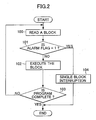
- Fig. 2 is a flowchart of the process that is carried out in the foreground
- Fig. 3 is a flowchart of the background process that is carried out simultaneously and in parallel with the foreground process.
- the foreground process shown in Fig. 2 is the same as the process of a regular processing program.
- the processing program is executed at the maximum feed speed andmaximum acceleration of the machines controlled by the numerical control apparatus 10, and further, movement commands to the respective axes, which are obtained by executing the processing program, are not outputted, but only numerical control is carried to perform a program checking.
- This background process is executed at a high speed and the first block of the processing program is read and stored in the register Re1 (Step 200), the memory content of said register Re1 is stored in the register Re2 (Step 201), and the next block is read from the processing program and stored in the register Re1 (Step 202).
- Step 203 a determination is made from the command content stored in the registers Re1 and Re2 as to whether the insertion condition of a block for corner R and chamfering set in advance by means of parameters.
- the condition for the insertion of the block for corner R and chamfering is set in advance by means of parameters.
- Step 203 Furthermore, ifdeterminedthattheconditionssetbymeans of the parameters at Step 203 are not met, then the process proceeds to Step 205, without inserting the block for corner R and chamfering, to execute the command in the block stored in the register Re2, thereby carrying out program checking.
- Step 205 the commanded feed speed is disregarded and the program is executed at the maximum feed speed and the maximum acceleration.
- a determination is made as to whether difference of the format of the processing program has caused the program abnormality so that an alarm has occurred or not, or as to whether the movement positions for the respective axes, obtained by execution of the program, has exceeded the stroke limit so that an alarm has occurred or not (Step 206). If there are not any format abnormalities and if any of the movement positions for the respective axes does not exceed the stroke limit, then the alarm will not occur, with the result that the process proceeds to Step 214.
- Step 207 an alarm flag is set to "1" in the memory in association with the current block (the block stored in the register Re2) and the program abnormality is stored (Step 208).
- the operator corrects the program abnormality through the display device/manual input unit 20, and when the program repair completion command is inputted (Step 209), the stored alarm flag is reset to "0" (Step 210).
- the CPU 11 stores the first block at the program checking position, brought back by the operator, in the register Re1 (Step 213). Then, a determination is made as to whether the program proceeds to the end or not (Step 214), and when proceeding to the end, the process returns to Step 201 and the above-described processes at Step 201 and following steps are carried out.
- the processing program is executed in the background at maximum feed speed and maximum acceleration and program checking is carried out a high speed without distributing movement commands to the respective axes.
- the alarm flag is set to "1" and correction of the program is carried out.
- the alarm flag is reset to "0".
- Step 100 a processing program which is the same as that of the prior art is carried out.
- the block is read (Step 100), and a determination is made as to whether the alarm flag for said block is set to "1" or not (Step 101).
- Step 101 the current block is executed and a movement command is distributed to the respective axes control circuits 30-32, so that the servomotors 50-52 for the respective axes are driven (Step 102).
- a determination is made as to whether the program proceeds to the end or not (Step 103).
- Step 103 When not proceeding to the end, the process returns to Step 100.
- Step 104 a single block interruption is carried out without executing the block which was read at Step 100 (Step 104). Thereafter, this interrupted state is maintained until a start command for resumption is inputted.
- a block for corner R and chamfering, inserted in the background process is executed as a block of processing program in this foreground process.
- speed reduction between the blocks may be reduced, and actual processing time may be shortened.
- the alarm flag is reset to "0" (Steps 208-210). Accordingly, when the operator, completing the correction of the program, inputs a start command for resumption, the processes at Step 100 and subsequent steps are started from the interrupted program position, in the foreground process. Also, as the background process is carried out at high speed, correction of the program tends to be completed prior to the interruption of an actual processing due to an occurrence of an alarm. When the correction of a program is complete, the alarm flag is reset to "0", so that processing can be continued without interruption.
Landscapes
- Engineering & Computer Science (AREA)
- Human Computer Interaction (AREA)
- Manufacturing & Machinery (AREA)
- Physics & Mathematics (AREA)
- General Physics & Mathematics (AREA)
- Automation & Control Theory (AREA)
- Numerical Control (AREA)
Applications Claiming Priority (2)
| Application Number | Priority Date | Filing Date | Title |
|---|---|---|---|
| JP2003318781 | 2003-09-10 | ||
| JP2003318781 | 2003-09-10 |
Publications (2)
| Publication Number | Publication Date |
|---|---|
| EP1515206A2 true EP1515206A2 (de) | 2005-03-16 |
| EP1515206A3 EP1515206A3 (de) | 2006-02-08 |
Family
ID=34132011
Family Applications (1)
| Application Number | Title | Priority Date | Filing Date |
|---|---|---|---|
| EP04255402A Withdrawn EP1515206A3 (de) | 2003-09-10 | 2004-09-07 | Numerisches Steuerungsgerät |
Country Status (3)
| Country | Link |
|---|---|
| US (1) | US7024269B2 (de) |
| EP (1) | EP1515206A3 (de) |
| CN (1) | CN1595319A (de) |
Cited By (2)
| Publication number | Priority date | Publication date | Assignee | Title |
|---|---|---|---|---|
| EP2037341A3 (de) * | 2007-09-14 | 2010-11-17 | Traub Drehmaschinen GmbH & Co. KG | Programmiersystem |
| DE102019128951B4 (de) | 2018-11-02 | 2022-09-29 | Fanuc Corporation | Alarmmeldesystem für einen Roboter |
Families Citing this family (10)
| Publication number | Priority date | Publication date | Assignee | Title |
|---|---|---|---|---|
| US7883855B2 (en) * | 2006-07-21 | 2011-02-08 | Abbott Laboratories | Immunosuppressant drug extraction reagent for immunoassays |
| JP2008134983A (ja) * | 2006-10-30 | 2008-06-12 | Fanuc Ltd | 加工再開機能を備えた数値制御装置 |
| US7914999B2 (en) * | 2006-12-29 | 2011-03-29 | Abbott Laboratories | Non-denaturing lysis reagent |
| EP2118656B1 (de) * | 2006-12-29 | 2012-08-29 | Abbott Laboratories | Verbessertes testverfahren für immunsuppressiva |
| WO2008082984A2 (en) | 2006-12-29 | 2008-07-10 | Abbott Laboratories | Non-denaturing lysis reagent for use with capture-in-solution immunoassay |
| ES2405364T3 (es) | 2006-12-29 | 2013-05-30 | Abbott Laboratories | Ensayo diagnóstico para la detección de una molécula o fármaco en sangre entera |
| JP4271248B2 (ja) * | 2007-05-24 | 2009-06-03 | ファナック株式会社 | 先読み停止機能を有する数値制御装置 |
| JP6105537B2 (ja) * | 2014-09-24 | 2017-03-29 | ファナック株式会社 | アラーム対処履歴を表示する数値制御装置 |
| CN106774227A (zh) * | 2017-03-09 | 2017-05-31 | 佛山市金银河智能装备股份有限公司 | 硅酮胶生产线故障诊断及处理系统 |
| JP6748146B2 (ja) * | 2018-05-17 | 2020-08-26 | ファナック株式会社 | 制御装置、制御方法及び制御プログラム |
Family Cites Families (10)
| Publication number | Priority date | Publication date | Assignee | Title |
|---|---|---|---|---|
| JPS5486887A (en) * | 1977-12-22 | 1979-07-10 | Toyoda Mach Works Ltd | Numerical controller |
| JPS5567805A (en) | 1978-11-15 | 1980-05-22 | Fanuc Ltd | Numerical value control unit |
| JPS62279408A (ja) * | 1986-05-28 | 1987-12-04 | Mitsubishi Electric Corp | 数値制御装置 |
| JPH01312605A (ja) | 1988-06-13 | 1989-12-18 | Sodick Co Ltd | 放電加工機 |
| JPH0253109A (ja) * | 1988-08-17 | 1990-02-22 | Okuma Mach Works Ltd | 数値制御加工プログラム検査方法 |
| JP2935706B2 (ja) * | 1988-12-07 | 1999-08-16 | ファナック株式会社 | 加工プログラム修正方法 |
| JPH06114679A (ja) * | 1992-10-06 | 1994-04-26 | Fanuc Ltd | 数値制御装置の加工プログラムチェック方法 |
| EP0766154B1 (de) * | 1992-12-28 | 2000-03-29 | Mitsubishi Denki Kabushiki Kaisha | Numerisch gesteuerte Werkzeugmaschine und Verfahren |
| KR100201020B1 (ko) * | 1994-03-11 | 1999-06-15 | 모리시타 요이찌 | 컴퓨터시뮬레이션부착 nc제어미세가공방법과 이 방법에 사용하는 장치 |
| US6804575B2 (en) * | 2000-10-26 | 2004-10-12 | Citizen Watch Co., Ltd. | Method and device for automatically preparing processing program |
-
2004
- 2004-09-07 CN CNA2004100746047A patent/CN1595319A/zh active Pending
- 2004-09-07 EP EP04255402A patent/EP1515206A3/de not_active Withdrawn
- 2004-09-09 US US10/936,665 patent/US7024269B2/en not_active Expired - Fee Related
Cited By (2)
| Publication number | Priority date | Publication date | Assignee | Title |
|---|---|---|---|---|
| EP2037341A3 (de) * | 2007-09-14 | 2010-11-17 | Traub Drehmaschinen GmbH & Co. KG | Programmiersystem |
| DE102019128951B4 (de) | 2018-11-02 | 2022-09-29 | Fanuc Corporation | Alarmmeldesystem für einen Roboter |
Also Published As
| Publication number | Publication date |
|---|---|
| US7024269B2 (en) | 2006-04-04 |
| CN1595319A (zh) | 2005-03-16 |
| US20050055126A1 (en) | 2005-03-10 |
| EP1515206A3 (de) | 2006-02-08 |
Similar Documents
| Publication | Publication Date | Title |
|---|---|---|
| US7024269B2 (en) | Numerical control apparatus | |
| JP4374045B2 (ja) | プログラム再開機能を備えた数値制御装置 | |
| EP0397887B1 (de) | Verfahren zur korrektur eines bearbeitungsprogramms | |
| US8155779B2 (en) | Numerical controller with tabular data for operating arbitrary axes | |
| US20070213866A1 (en) | Machine with program check function | |
| CN111190391B (zh) | 数值控制装置 | |
| JP2006004275A (ja) | 数値制御装置 | |
| JP4282631B2 (ja) | テーブル形式データで運転を行う数値制御装置 | |
| CN107436589B (zh) | 具备用于解决警报的程序修正支援功能的数值控制装置 | |
| US10048677B2 (en) | Numerical controller that shortens cycle time of machining program | |
| JPH11143514A (ja) | 加工誤差チェックができる数値制御装置 | |
| US10915093B2 (en) | Numerical controller | |
| US6397123B1 (en) | Numerical control apparatus | |
| US7095203B2 (en) | Numerical controller | |
| US10162335B2 (en) | Numerical controller capable of neighboring point search with consideration for tool attitude | |
| JP4044105B2 (ja) | 系統毎に運転手段を切り替える機能を有する数値制御装置 | |
| JP4116640B2 (ja) | 多系統制御機能を有する数値制御装置 | |
| CN111796555B (zh) | 数值控制装置 | |
| JP2005108205A (ja) | 数値制御装置 | |
| JP4233559B2 (ja) | 数値制御工作機械 | |
| US20060052900A1 (en) | Numerical control apparatus | |
| JPH11143505A (ja) | 停電後の電源回復時における機械の自動復旧装置 | |
| JPH08211918A (ja) | Cncの位置制御方式 | |
| JP2008130013A (ja) | 数値制御装置 | |
| JPH08263120A (ja) | Cncの現在位置表示方式 |
Legal Events
| Date | Code | Title | Description |
|---|---|---|---|
| PUAI | Public reference made under article 153(3) epc to a published international application that has entered the european phase |
Free format text: ORIGINAL CODE: 0009012 |
|
| AK | Designated contracting states |
Kind code of ref document: A2 Designated state(s): AT BE BG CH CY CZ DE DK EE ES FI FR GB GR HU IE IT LI LU MC NL PL PT RO SE SI SK TR |
|
| AX | Request for extension of the european patent |
Extension state: AL HR LT LV MK |
|
| PUAL | Search report despatched |
Free format text: ORIGINAL CODE: 0009013 |
|
| AK | Designated contracting states |
Kind code of ref document: A3 Designated state(s): AT BE BG CH CY CZ DE DK EE ES FI FR GB GR HU IE IT LI LU MC NL PL PT RO SE SI SK TR |
|
| AX | Request for extension of the european patent |
Extension state: AL HR LT LV MK |
|
| AKX | Designation fees paid | ||
| REG | Reference to a national code |
Ref country code: DE Ref legal event code: 8566 |
|
| STAA | Information on the status of an ep patent application or granted ep patent |
Free format text: STATUS: THE APPLICATION IS DEEMED TO BE WITHDRAWN |
|
| 18D | Application deemed to be withdrawn |
Effective date: 20060814 |