EP1515175A1 - Lichtvermenger - Google Patents
Lichtvermenger Download PDFInfo
- Publication number
- EP1515175A1 EP1515175A1 EP03725710A EP03725710A EP1515175A1 EP 1515175 A1 EP1515175 A1 EP 1515175A1 EP 03725710 A EP03725710 A EP 03725710A EP 03725710 A EP03725710 A EP 03725710A EP 1515175 A1 EP1515175 A1 EP 1515175A1
- Authority
- EP
- European Patent Office
- Prior art keywords
- optical
- mixing plate
- hollow motor
- optical mixer
- optical mixing
- Prior art date
- Legal status (The legal status is an assumption and is not a legal conclusion. Google has not performed a legal analysis and makes no representation as to the accuracy of the status listed.)
- Withdrawn
Links
Images




Classifications
-
- G—PHYSICS
- G02—OPTICS
- G02B—OPTICAL ELEMENTS, SYSTEMS OR APPARATUS
- G02B27/00—Optical systems or apparatus not provided for by any of the groups G02B1/00 - G02B26/00, G02B30/00
- G02B27/09—Beam shaping, e.g. changing the cross-sectional area, not otherwise provided for
- G02B27/0933—Systems for active beam shaping by rapid movement of an element
-
- G—PHYSICS
- G02—OPTICS
- G02B—OPTICAL ELEMENTS, SYSTEMS OR APPARATUS
- G02B27/00—Optical systems or apparatus not provided for by any of the groups G02B1/00 - G02B26/00, G02B30/00
- G02B27/48—Laser speckle optics
Definitions
- This invention relates to an optical mixer in which a hollow motor is used to rotate an optical mixing plate at a peripheral speed of at least 1800 times per minute relative to the laser beam diameter to convert coherent light into virtually incoherent light.
- a method to simply pass a laser beam through a rotating diffusion plate is conventionally used in laboratories to solve problems caused by coherence that are unique to the laser beam. This method, however, is unable to remove speckle patterns from the excellent coherence unique to the laser beam.
- the laser beam is merely homogenized.
- an optical fiber lightguide is set between the laser beam and microscope, and the length of the light path is modified by vibrating the lightguide using a piezoelectric element or speaker-vibrated membrane.
- a lightguide optical fibers
- the laser beam becomes incoherent in terms of time at a frequencies lower than the vibration frequency.
- the above system that vibrates a lightguide set between laser beam and microscope to change the length of the light path is not an optical component easily built into optical systems.
- a unit incorporating such a system is not compact and the cost is rather high.
- the coherence of the laser beam has the effect of generating a complex diffraction pattern due to interference of the reflected light from all surfaces, dirty optical elements, and scattered light from damaged optical parts.
- This invention intends to solve these conventional problems by providing an optical mixer that converts the coherence of the laser beams into virtual incoherence by rapidly changing the length of the light path and using the light mixing effect.
- the light mixer of this invention can be used as an additional optical component in any optical system to realize a compact and inexpensive equipment.
- optical mixing plate includes both nonperiodic random structures such as a lemon skin filter and beam- forming diffuser and periodic structures such as a holographic plate (diffraction pattern generator), fly's-eye lens, and micro-lens array;
- optical mixer in which said optical mixing plate is constructed as thin as possible and is installed as close as possible to the end face on the laser emitting side;
- optical mixer in which said hollow motor rotating at high speed is supported within the housing via cushions.
- Figure 1 is the front view of the first embodiment of this invention.
- Figure 2 is an enlarged sectional view of section A-A in Figure 1.
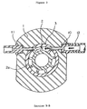
- Figure 3 is the sectional view of section B-B in Figure 2.
- An air motor is used to drive the hollow motor in this embodiment.
- the body 1 has a cylindrical through-hole at the center as shown in Figure 2.
- the rotating center shaft equipped with vanes 2 is held in place by angular bearings 4 and 4, circular glass retaining fixture 6, and stepped fixation rings 7 and 7 so that the rotating center shaft can rotate freely.
- the inner rings of the angular bearings 4 holding the rotating center shaft 2 in place are fixed directly or by the stepped fixation ring 7 via spring washer 5.
- the side of the outer ring of the angular bearing 4 is fixed by the circular glass retaining fixture 6.
- Spring washer 5 is used on the right side only in Figure 2. It is possible to use this washer on the left side or on both sides.
- the rotating center shaft equipped with vanes 2 is provided with a through hole 2b at the center to allow the laser beams to pass through it.
- Multiple vanes 2a are formed on the periphery of the center shaft at equal distances as shown in Figure 3.
- the rotating center shaft 2 rotates when high pressure air strikes the vanes 2a.
- Said vanes are located between angular bearings 4 and 4 as shown in Figure 2.
- the intermediate tube 3 is placed around the vanes.
- High pressure air is jetted from air jet port 10 (to be described later) at vanes 2a to rotate the rotating center shaft 2.
- the body 1 is provided with an air jet port 10 and an air discharge port 11, which are connected to each other to form a flow path. Said vanes 2a are located in said flow path.
- the air jet port 10 is connected to an air compressor via tube 12.
- vanes 2a, intermediate tube 3, and angular bearings 4 are not necessarily limited to those shown in the figures. Various other means may be used provided that high pressure air strikes the vanes 2a on the rotating center shaft 2 to rotate it at high speed.
- stepped fixation ring 7 with a through hole at the center is mounted on the laser beam exit side of the rotating center shaft equipped with vanes 2 via the spring washer 5.
- the optical mixing plate 8 is fitted into the through hole of the stepped fixation ring 7 using an appropriate means (adhesive, screws, etc.) so that the optical mixing plate 8 rotates at high speed together with the rotating center shaft equipped with vanes 2.
- a circular glass retaining fixture 6 is mounted on either end and outside of the rotating center shaft equipped with vanes 2.
- a window glass 9 is fastened to each of said circular glass retaining fixtures 6 using an appropriate means.
- optical mixer constructed as above, laser beams enter the window glass 9 on the left side as shown in Figure 2, pass through the hole 2b of the rotating center shaft 2 and optical mixing plate 8, and exit from the window glass 9 on the right side.
- Said optical mixing plate should preferably be located as close as possible to the end face of the body on the laser beam exit side.
- the optical mixer should also be constructed as thin as possible.
- the optical mixer constructed as above is described below.
- a lemon skin filter (diffuser) is used as the optical mixing plate.
- a typical lemon skin filter is an assembly of convex lenses with random, different and small focal distances.
- plate glasses are frosted by rough grinding and chemically etched to reduce scattering. This treatment gives the surface the appearance of lemon skin.
- the product is therefore not an assembly of convex lenses with uniform small focal distances (a micro-lens array) but a random, nonperiodic structure consisting of convex and concave lenses of random focal distances.
- the rotating center shaft equipped with vanes 2 of the hollow motor rotates at high speed (e.g. at a peripheral speed of at least 1800 times per minute relative to the laser beam diameter) when struck by high-pressure air from the air compressor jetted from the air jet port 10.
- the laser beams enter the window glass 9 on the left side as shown in Figure 2, pass through the hole 2b of the rotating center shaft with vanes 2 and optical mixing plate 8, and exit from the window glass 9 on the right side.
- the laser beams are scattered on the lemon skin filter which retains the effects of its assembly of convex and concave lenses with random, different and small focal distances.
- the filter rotates, the scattered laser beams are mixed and the length of the light path changes quickly.
- the incident laser beams are virtually incoherent in terms of time average.
- the center shaft of the hollow motor can rotate at a speed of more than 10,000 rpm.
- a laser beam 1 mm in diameter is emitted to an area 3.2 mm in radius around the center of the optical mixing plate, radiations of different states (different wave trains) are emitted 200,000 times per minute. Incoherence of the laser beam is virtually guaranteed, assuming time average, at frequencies lower than at least 3.3 kHz.
- the above optical mixing plate may be, in place of a lemon skin filter, a frosted glass obtained immediately before optical polishing called a diffusion plate or a beam-forming diffuser from Physical Optics Corporation.
- This beam-forming diffuser has a surface relief hologram and has the same effects as an array of micro-concave lenses.
- Other holographic plates available include a diffractive optical element marketed by Edmund Optics Japan as a diffraction pattern generator product.
- the coherence unique to the laser beam can also be made incoherent in terms average, by the use of time of periodical structures such as fly's-eye lenses and micro-lens arrays depending on the way such components are used.
- FIG. 4 shows a sectional view and a side view of the second embodiment of this invention using a flat coreless electric motor.
- the outer rings of the two angular bearings 24 are press-fitted into outer tube 21 by double combination.
- the rotating center shaft with yoke 22 is fitted into the inner rings of angular bearings 24 and fastened by the fixation ring with lid 23 via spring washer 31.
- a through hole 22a passes through the center of the rotating center shaft with yoke 22.
- the yoke 27 is fastened to the center shaft 22 by a pan head screw 34.
- a magnet 28 is fastened to said yoke 27.
- the yoke 27 is provided with a through hole 27a at the center, which connects to through hole 22a.
- the optical mixing plate 29 is mounted on the outlet of through hole 27a and fixed by a suitable means (adhesion, etc.).
- a case 30, fastened to the outer tube 21, is mounted on the outside of the optical mixing plate 29.
- the rotating center shaft with yoke 22 rotates together with the integrally mounted spring washer 31 and fixation ring with lid 23. It is also possible to use other support means replacing spring washer 31 and fixation ring with lid 23 and to support only the rotating center shaft with yoke 22 on the angular bearings and rotate it.
- Coil support plate 25 is fastened to the outer tube 21 by machine screw 33.
- Coil 26, set on the coil support plate 25, connects to a power supply (not shown) via a cable.
- Coil 26, yoke 27, and magnet 28 comprise the conventionally known flat coreless electric motor.
- optical mixer of this invention constructed as above, when coil 26 is energized, magnet 28 and yoke 27 rotate, and the optical mixing plate 29 also rotates. It is possible, as in the first embodiment of this invention, to make the laser beam passing through optical mixing plate 29 virtually incoherent. Since the operating principle of the electric motor is identical to that of a conventionally known flat coreless motor, a detailed explanation is omitted here.
- the third embodiment of this invention features an anti-vibration means.
- Figure 5 shows a section of the embodiment of this invention in which the hollow motor is supported by O-rings as cushions.
- the optical mixer is supported on the housing via the O-rings placed along the periphery and on both the right and left sides of said optical mixer. Vibration transferred to the housing is absorbed by the O-rings.
- the rotor is symmetrically structured in terms of both mass and shape which prevents vibrations of 100 Hz and below that are harmful for microscope and measuring equipment. The remaining high harmonic vibrations can easily be prevented by installing O-rings or other cushions in the housing.
- optical mixer of this invention Some specific structures of the optical mixer of this invention have been introduced. The use the optical mixer of this invention is described below. The drawings referred to in the description below show only the relationship between the optical mixing plate and laser beams.
- Figure 6 shows an example of typical applications in which laser beams enter the optical mixing plate that is parallel to the beams and no condenser lens is used after said plate.
- Figure 7 shows an example of applications in which parallel laser beams enter the optical mixing plate.
- the secondary light source image created by a periodic structure is converted into a parallel light flux by means of a condenser lens.
- FIG 8 shows laser beams that are focused on the optical mixing plate and then used as parallel light flux by lenses or other means. (This also applies to the optical mixing plate that is installed in the reverse beam expander.)
- Lemon skin filters and beam-forming diffusers can be used as random nonperiodic structures in any of methods shown in Figures 6, 7 and 8.
- Figure 9 is an example of applications of the optical mixing plate of this invention in which a tilted flat parallel plate is used in place of the optical mixing plate.
- laser beams are aimed at the rotating center shaft and refracted on the flat parallel plate, and an orbicular light is generated as the hollow motor rotates.
- the radius of the annulus light depends on the angle of tilt and the thickness of the flat parallel plate.
- FIGus illumination introduces laser beams to the margins of the objective lens of a microscope and generates fluorescence through total internal reflection (at the interface between glass and solution) (excitation of evanescent waves).
- Figure 10 shows another example of an application of the optical mixing plate of this invention in which a wedge prism is used in place of the optical mixing plate.
- the orbicular light can be mixed using the hollow motor. It is also possible to design the unit compactly and make it symmetrical about the rotating center shaft in terms of both shape and mass, which serves to reduce vibrations significantly.
- optical mixer with a hollow motor of this invention has been described.
- Other means of driving the hollow motor may be used including, for example, a gear drive.
- the optical mixing plate and the method of using it are not limited to what is described above but various other utilization methods can be adopted.
- This invention enables the construction of a compact optical mixer. It is therefore easy to incorporate it in optical equipment or install it as an external unit on existing equipment. It is also easy to make the laser beam virtually incoherent at frequencies lower than at least 3.3 kHz. In this state, speckle patterns, which cause problems in a wide range of applications, are completely removed from ordinary detectors. It is also easy to realize virtual incoherence at frequencies lower than 30 kHz assuming minor changes in the setting conditions.
- the motor load is low, and a super high-speed, low vibration optical mixer is realized because the use of a hollow motor allows the use of a compact circular optical mixing plate.
- the compact optical mixing plate can be installed as close as possible to the end face on the laser emitting side.
- a thin optical mixer has been designed. Because of these structural features, the light spread from optical mixing plate, not limited to laser beams, is collected effectively by lenses, making it possible to enlarge and homogenize the light source image and otherwise expand the fields of practical application.
- the optical mixer of this invention is easily built into optical equipment or can be externally attached.
- annulus illumination from parallel annulus light or annulus light with an angle of inclination can be formed within a lighting system such as microscope or exposure device, with the unnecessary interference fringes removed.
Landscapes
- Physics & Mathematics (AREA)
- General Physics & Mathematics (AREA)
- Optics & Photonics (AREA)
- Lasers (AREA)
- Mechanical Light Control Or Optical Switches (AREA)
Applications Claiming Priority (3)
| Application Number | Priority Date | Filing Date | Title |
|---|---|---|---|
| JP2002176726A JP2004020988A (ja) | 2002-06-18 | 2002-06-18 | 光攪拌器 |
| JP2002176726 | 2002-06-18 | ||
| PCT/JP2003/005521 WO2003107071A1 (ja) | 2002-06-18 | 2003-04-30 | 光攪拌器 |
Publications (2)
| Publication Number | Publication Date |
|---|---|
| EP1515175A1 true EP1515175A1 (de) | 2005-03-16 |
| EP1515175A4 EP1515175A4 (de) | 2006-08-09 |
Family
ID=29728114
Family Applications (1)
| Application Number | Title | Priority Date | Filing Date |
|---|---|---|---|
| EP03725710A Withdrawn EP1515175A4 (de) | 2002-06-18 | 2003-04-30 | Lichtvermenger |
Country Status (4)
| Country | Link |
|---|---|
| US (1) | US20050226556A1 (de) |
| EP (1) | EP1515175A4 (de) |
| JP (1) | JP2004020988A (de) |
| WO (1) | WO2003107071A1 (de) |
Cited By (1)
| Publication number | Priority date | Publication date | Assignee | Title |
|---|---|---|---|---|
| WO2017017271A1 (de) * | 2015-07-29 | 2017-02-02 | Georg-August-Universität Göttingen Stiftung Öffentlichen Rechts Universitätsmedizin | Fluoreszenz-mikroskop |
Families Citing this family (5)
| Publication number | Priority date | Publication date | Assignee | Title |
|---|---|---|---|---|
| US7948606B2 (en) | 2006-04-13 | 2011-05-24 | Asml Netherlands B.V. | Moving beam with respect to diffractive optics in order to reduce interference patterns |
| US7728954B2 (en) | 2006-06-06 | 2010-06-01 | Asml Netherlands B.V. | Reflective loop system producing incoherent radiation |
| US7649676B2 (en) * | 2006-06-14 | 2010-01-19 | Asml Netherlands B.V. | System and method to form unpolarized light |
| JP2011059265A (ja) * | 2009-09-08 | 2011-03-24 | Sharp Corp | プロジェクタ装置 |
| US11273520B2 (en) * | 2019-01-31 | 2022-03-15 | General Electric Company | System and method for automated laser ablation |
Family Cites Families (9)
| Publication number | Priority date | Publication date | Assignee | Title |
|---|---|---|---|---|
| US3588249A (en) * | 1968-06-17 | 1971-06-28 | Robert H Studebaker | Laser beam survey apparatus |
| JP2602648B2 (ja) * | 1987-01-14 | 1997-04-23 | キヤノン株式会社 | 回転駆動装置 |
| US4948253A (en) * | 1988-10-28 | 1990-08-14 | Zygo Corporation | Interferometric surface profiler for spherical surfaces |
| JP3075381B2 (ja) * | 1992-02-17 | 2000-08-14 | 株式会社ニコン | 投影露光装置及び転写方法 |
| JP3713632B2 (ja) * | 1994-12-28 | 2005-11-09 | 富士写真フイルム株式会社 | インクカートリッジ、及びインクジェットプリンタ |
| US5621529A (en) * | 1995-04-05 | 1997-04-15 | Intelligent Automation Systems, Inc. | Apparatus and method for projecting laser pattern with reduced speckle noise |
| JPH09243964A (ja) * | 1996-03-14 | 1997-09-19 | Sony Corp | 露光照明装置 |
| US6081381A (en) * | 1998-10-26 | 2000-06-27 | Polametrics, Inc. | Apparatus and method for reducing spatial coherence and for improving uniformity of a light beam emitted from a coherent light source |
| JP2002148556A (ja) * | 2000-11-15 | 2002-05-22 | Olympus Optical Co Ltd | 光路長スキャニング機構及びそれを備えた光学装置 |
-
2002
- 2002-06-18 JP JP2002176726A patent/JP2004020988A/ja active Pending
-
2003
- 2003-04-30 EP EP03725710A patent/EP1515175A4/de not_active Withdrawn
- 2003-04-30 US US10/516,109 patent/US20050226556A1/en not_active Abandoned
- 2003-04-30 WO PCT/JP2003/005521 patent/WO2003107071A1/ja not_active Ceased
Cited By (1)
| Publication number | Priority date | Publication date | Assignee | Title |
|---|---|---|---|---|
| WO2017017271A1 (de) * | 2015-07-29 | 2017-02-02 | Georg-August-Universität Göttingen Stiftung Öffentlichen Rechts Universitätsmedizin | Fluoreszenz-mikroskop |
Also Published As
| Publication number | Publication date |
|---|---|
| JP2004020988A (ja) | 2004-01-22 |
| EP1515175A4 (de) | 2006-08-09 |
| WO2003107071A1 (ja) | 2003-12-24 |
| US20050226556A1 (en) | 2005-10-13 |
Similar Documents
| Publication | Publication Date | Title |
|---|---|---|
| US6081381A (en) | Apparatus and method for reducing spatial coherence and for improving uniformity of a light beam emitted from a coherent light source | |
| JP5317074B2 (ja) | レーザ照明装置 | |
| JP3107388U (ja) | 高強度非コヒーレント光提供用及びスペックル低減用の装置 | |
| US9448416B2 (en) | Light source device and projection-type display device | |
| Mattheyses et al. | Effective elimination of laser interference fringing in fluorescence microscopy by spinning azimuthal incidence angle | |
| CN109270703B (zh) | 一种消散斑光路及三色激光投影系统 | |
| JP2009512883A (ja) | レーザ・スペックルを低減する方法および装置 | |
| GB2462444A (en) | Image projection apparatus and method | |
| JP2007233371A (ja) | レーザ照明装置 | |
| WO2009118880A1 (ja) | 照明装置及びプロジェクタ | |
| JP2004038139A (ja) | 顕微鏡内への光線連結のための装置 | |
| JP2004138669A (ja) | 照明装置及び画像表示装置 | |
| KR20010086321A (ko) | 적응 미러 | |
| EP1515175A1 (de) | Lichtvermenger | |
| JP2009527772A (ja) | レーザ投影ディスプレイのための角度走査によるスペックル低減装置及び方法 | |
| CN113031295A (zh) | 一种散斑抑制装置、光学设备及激光显示系统 | |
| JPH07297111A (ja) | 露光照明装置 | |
| JP2002523799A (ja) | 一体的に形成された表面ディフューザを有する光学要素を備える装置 | |
| JP2021006902A (ja) | マイクロスコープシステム用放射線デリバリ装置 | |
| CN113835232A (zh) | 一种消散斑装置、激光投影成像系统及激光照明成像系统 | |
| EP4185912A1 (de) | Verfahren und vorrichtungen zur kontrastoptimierung zur verwendung mit verdeckten bildgebungssystemen | |
| CN100504148C (zh) | 光学组件及相应的照明设备 | |
| JP2003275888A (ja) | レーザ加工装置及び加工方法 | |
| WO2020202011A1 (en) | Speckle reduced laser image projection method and apparatus | |
| JPH06319092A (ja) | 頭部装着式ディスプレイ |
Legal Events
| Date | Code | Title | Description |
|---|---|---|---|
| PUAI | Public reference made under article 153(3) epc to a published international application that has entered the european phase |
Free format text: ORIGINAL CODE: 0009012 |
|
| 17P | Request for examination filed |
Effective date: 20041021 |
|
| AK | Designated contracting states |
Kind code of ref document: A1 Designated state(s): AT BE BG CH CY CZ DE DK EE ES FI FR GB GR HU IE IT LI LU MC NL PT RO SE SI SK TR |
|
| RBV | Designated contracting states (corrected) |
Designated state(s): GB |
|
| REG | Reference to a national code |
Ref country code: DE Ref legal event code: 8566 |
|
| A4 | Supplementary search report drawn up and despatched |
Effective date: 20060710 |
|
| STAA | Information on the status of an ep patent application or granted ep patent |
Free format text: STATUS: THE APPLICATION IS DEEMED TO BE WITHDRAWN |
|
| 18D | Application deemed to be withdrawn |
Effective date: 20071101 |