EP1515085A2 - UV lamp assembly and use thereof - Google Patents
UV lamp assembly and use thereof Download PDFInfo
- Publication number
- EP1515085A2 EP1515085A2 EP20040021097 EP04021097A EP1515085A2 EP 1515085 A2 EP1515085 A2 EP 1515085A2 EP 20040021097 EP20040021097 EP 20040021097 EP 04021097 A EP04021097 A EP 04021097A EP 1515085 A2 EP1515085 A2 EP 1515085A2
- Authority
- EP
- European Patent Office
- Prior art keywords
- lamp
- reflector
- reflector body
- base
- arrangement
- Prior art date
- Legal status (The legal status is an assumption and is not a legal conclusion. Google has not performed a legal analysis and makes no representation as to the accuracy of the status listed.)
- Granted
Links
- 230000003287 optical effect Effects 0.000 claims abstract description 4
- 230000005855 radiation Effects 0.000 claims description 20
- 239000011521 glass Substances 0.000 claims description 17
- 239000000853 adhesive Substances 0.000 claims description 10
- 230000001070 adhesive effect Effects 0.000 claims description 10
- 239000002184 metal Substances 0.000 claims description 7
- 229910052751 metal Inorganic materials 0.000 claims description 7
- 239000011248 coating agent Substances 0.000 claims description 5
- 238000000576 coating method Methods 0.000 claims description 5
- 238000001816 cooling Methods 0.000 claims description 3
- 239000002241 glass-ceramic Substances 0.000 claims description 3
- 239000000463 material Substances 0.000 claims description 3
- 239000004033 plastic Substances 0.000 claims description 3
- 229910001507 metal halide Inorganic materials 0.000 claims description 2
- 150000005309 metal halides Chemical class 0.000 claims description 2
- 229910000679 solder Inorganic materials 0.000 claims description 2
- QSHDDOUJBYECFT-UHFFFAOYSA-N mercury Chemical compound [Hg] QSHDDOUJBYECFT-UHFFFAOYSA-N 0.000 abstract description 2
- 239000004020 conductor Substances 0.000 abstract 1
- 229910052753 mercury Inorganic materials 0.000 abstract 1
- 241001295925 Gegenes Species 0.000 description 4
- 230000000712 assembly Effects 0.000 description 4
- 238000000429 assembly Methods 0.000 description 4
- 239000000919 ceramic Substances 0.000 description 4
- 239000004904 UV filter Substances 0.000 description 3
- 230000002349 favourable effect Effects 0.000 description 2
- 238000009434 installation Methods 0.000 description 2
- 229920001296 polysiloxane Polymers 0.000 description 2
- 0 CC=CCC1(CC1)*1=CCC=C1 Chemical compound CC=CCC1(CC1)*1=CCC=C1 0.000 description 1
- 240000007594 Oryza sativa Species 0.000 description 1
- 235000007164 Oryza sativa Nutrition 0.000 description 1
- VYPSYNLAJGMNEJ-UHFFFAOYSA-N Silicium dioxide Chemical compound O=[Si]=O VYPSYNLAJGMNEJ-UHFFFAOYSA-N 0.000 description 1
- 239000002253 acid Substances 0.000 description 1
- 239000005388 borosilicate glass Substances 0.000 description 1
- 239000004568 cement Substances 0.000 description 1
- 229910044991 metal oxide Inorganic materials 0.000 description 1
- 150000004706 metal oxides Chemical class 0.000 description 1
- 235000009566 rice Nutrition 0.000 description 1
Images


Classifications
-
- F—MECHANICAL ENGINEERING; LIGHTING; HEATING; WEAPONS; BLASTING
- F21—LIGHTING
- F21V—FUNCTIONAL FEATURES OR DETAILS OF LIGHTING DEVICES OR SYSTEMS THEREOF; STRUCTURAL COMBINATIONS OF LIGHTING DEVICES WITH OTHER ARTICLES, NOT OTHERWISE PROVIDED FOR
- F21V17/00—Fastening of component parts of lighting devices, e.g. shades, globes, refractors, reflectors, filters, screens, grids or protective cages
- F21V17/10—Fastening of component parts of lighting devices, e.g. shades, globes, refractors, reflectors, filters, screens, grids or protective cages characterised by specific fastening means or way of fastening
- F21V17/14—Bayonet-type fastening
-
- F—MECHANICAL ENGINEERING; LIGHTING; HEATING; WEAPONS; BLASTING
- F21—LIGHTING
- F21V—FUNCTIONAL FEATURES OR DETAILS OF LIGHTING DEVICES OR SYSTEMS THEREOF; STRUCTURAL COMBINATIONS OF LIGHTING DEVICES WITH OTHER ARTICLES, NOT OTHERWISE PROVIDED FOR
- F21V17/00—Fastening of component parts of lighting devices, e.g. shades, globes, refractors, reflectors, filters, screens, grids or protective cages
- F21V17/06—Fastening of component parts of lighting devices, e.g. shades, globes, refractors, reflectors, filters, screens, grids or protective cages the fastening being onto or by the lampholder
-
- A—HUMAN NECESSITIES
- A61—MEDICAL OR VETERINARY SCIENCE; HYGIENE
- A61N—ELECTROTHERAPY; MAGNETOTHERAPY; RADIATION THERAPY; ULTRASOUND THERAPY
- A61N5/00—Radiation therapy
- A61N5/06—Radiation therapy using light
- A61N5/0613—Apparatus adapted for a specific treatment
- A61N5/0614—Tanning
-
- F—MECHANICAL ENGINEERING; LIGHTING; HEATING; WEAPONS; BLASTING
- F21—LIGHTING
- F21V—FUNCTIONAL FEATURES OR DETAILS OF LIGHTING DEVICES OR SYSTEMS THEREOF; STRUCTURAL COMBINATIONS OF LIGHTING DEVICES WITH OTHER ARTICLES, NOT OTHERWISE PROVIDED FOR
- F21V19/00—Fastening of light sources or lamp holders
- F21V19/006—Fastening of light sources or lamp holders of point-like light sources, e.g. incandescent or halogen lamps, with screw-threaded or bayonet base
-
- F—MECHANICAL ENGINEERING; LIGHTING; HEATING; WEAPONS; BLASTING
- F21—LIGHTING
- F21V—FUNCTIONAL FEATURES OR DETAILS OF LIGHTING DEVICES OR SYSTEMS THEREOF; STRUCTURAL COMBINATIONS OF LIGHTING DEVICES WITH OTHER ARTICLES, NOT OTHERWISE PROVIDED FOR
- F21V27/00—Cable-stowing arrangements structurally associated with lighting devices, e.g. reels
- F21V27/02—Cable inlets
Definitions
- the invention relates to a UV lamp assembly with a lamp base, with one on the lamp base arranged, concave reflector body, with a within the cavity of the reflector body and arranged on the lamp base UV burner, in particular with a filter disc, which covers an outlet opening of the reflector body for UV radiation.
- the invention further relates to a use of this UV lamp assembly.
- Such lamp arrangements are known from WO 97/32158 for tanning equipment.
- a glass bulb which is covered inside with a reflection layer, here is a high pressure mercury vapor lamp standing arranged as a tanning spot.
- the glass bulb is from completed a UV filter.
- the filter and / or the tanning lamp is interchangeable.
- the glass bulb for tanning and to seal the UV filter by means of seals airtight to the glass top
- a change of the UV filter or the radiator proves to be problematic regarding a new seal.
- EP 301 208 discloses a bayonet socket for a lamp or a reflector, wherein the Bayonet catch the lamp base fixed in a lamp holder. Between the reflector and the bayonet socket plug or clamp connections are disclosed, wherein the reflector can be detached from the socket.
- DE 20106885U1 also discloses a lamp with a bayonet base, wherein the bayonet closure fixed the base in a lamp socket.
- the lamp has one of the bayonet socket unscrewable lamp bulb on.
- the reflector body via a bayonet lock solvable connected to the lamp base.
- the reflector body including a filter glass by a simple Handle are removed, so that the burner is directly accessible. It is now possible Either replace the burner alone or replace it with the base.
- the reflector body and a filter disc optionally arranged thereon can be reused.
- the object is also achieved in that the reflector body via at least two gripping arms connected to the lamp base.
- Such a configuration allows as the Bayonet lock a simple replacement of the UV burner in case of failure and a Reuse of all remaining components such as reflector, filter glass, lamp base, electrical connections and gripping arms.
- optical radiation can be generated with a radiator.
- the radiator maximum in the VIS or IR it is a VIS or IR lamp assembly with a VIS or IR burner whose reflector is preferably a VIS or Has IR-reflective layer.
- the reflector can be transparent to UV radiation be.
- the lamp assembly for UV radiation is provided with a UV emitter is generated.
- the reflector body has a reflector neck and the reflector neck is detachably connected to the lamp base via the bayonet lock, or else if the reflector body at the radiator opening of the reflector via a bayonet closure or releasably connected to the lamp base with gripper arms.
- the reflector body preferably has a coating which reflects UV radiation on.
- the reflector body is formed from glass or glass ceramic is and its coating is transparent to infrared radiation. This is how heat gets out of Reflector removed and cooling of the reflector body can be omitted.
- the reflector body has facets. Furthermore, it has proven useful if the UV radiation-reflecting coating of the reflector body contains at least one metal oxide.
- the filter disc with the reflector body by an elastic adhesive connected is advantageous if the filter disc with the reflector body by an elastic adhesive connected.
- a silicone-based adhesive is chosen
- the filter disk is connected to the reflector body in such a way that openings remain, via which an air exchange between a space outside and the space inside the reflector body can take place. It has proven useful if the reflector body has at least one half-moon-shaped recess in the region of the outlet opening on its circumference.
- the lamp cap made of ceramic, plastic or metal is formed.
- ceramic is particularly preferred, since it is not only high temperature resistant but is also electrically insulating, so that the electrical connections for the UV burner is not separately electrically isolated from the base.
- the reflector neck and the reflector body of the same Material are formed in one piece, wherein the reflector neck nubs are formed, so that it can be connected directly to the lamp base.
- the reflector neck and the reflector body are formed of the same material and in one piece, wherein the reflector neck is connected to a configured as a ring further component, are formed on which nubs, so that the ring is directly connected to the lamp cap can be.
- the ring may be formed of metal, plastic or ceramic. It has proven useful if the ring is connected to the reflector neck by means of glass solder or adhesive or the ring is shrunk onto the reflector neck. Both single- and multi-component adhesives are suitable for this purpose. In particular, it is preferred if the adhesive is an inorganic adhesive such as acid rice cement or if the adhesive is silicone based.
- the UV burner preferably has a lamp bulb made of silica glass and electrical contacts, which are passed through this gas-tight either on one side or on opposite sides of the lamp envelope.
- a use of the UV lamp assembly according to the invention without forced cooling in one Power range from 100W to 300W is ideal.
- At least one UV lamp assembly in a tanning device. It has proven particularly useful if the at least one UV lamp assembly by means of two retaining screws, which are arranged at a distance of 25 - 27mm to each other, is mounted in the tanning device.
- the at least one UV lamp assembly by means of two Retaining screws, which are arranged at a distance of 29 - 31mm to each other, in the Tanning device is mounted.
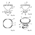
- Figure 1a shows a UV lamp assembly 1 in the side view with a two-part, rectangular Lamp base 2 and a reflector body 3 made of glass.
- the outlet opening of the reflector body 3 for UV radiation is covered with a filter disk 4.
- the reflector body 3 a reflector neck 3a, which has a bayonet lock directly to the Lamp base 2 is connected.
- crescent-shaped recesses 3b arranged such that openings 6 allow an exchange of air to the space in the reflector body 3.
- On the lamp base 2 are a spring 5a and retaining screws 5b for installation of the UV lamp assembly 1 in a Tanning device available.
- FIG. 1b shows the UV lamp arrangement 1 from FIG. 1 in a further side view, however turned by 90 degrees. It can be seen that the two parts of the two-part lamp cap 2 are connected by rivets or screw 2a.
- FIG. 1c shows the UV lamp arrangement 1 from FIGS. 1a and 1b in plan view.
- FIG. 1d shows the UV lamp arrangement 1 from FIGS. 1a to 1c in a three-dimensional view.
- Figure 1e shows the detail A of Figure 1d in an enlarged view.
- the bayonet lock clearly visible between the reflector body 3 and the lamp cap 2.
- openings 2b in the lamp base 2 are present, through which on both sides of the lamp cap 2 electrical connections of a not visible here, in the reflector body 3 arranged UV burner are performed.
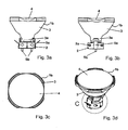
- FIG. 2 a shows a side view of a further UV lamp arrangement 1 a with a two-part, round lamp base 2 and a reflector body 3 made of glass.
- the exit opening of the Reflector body 3 for UV radiation is covered with a filter disk 4.
- the Reflector body 3 a reflector neck 3a, which has a bayonet directly with the Lamp base 2 is connected.
- the filter disk 4 covers the region of the outlet opening of the reflector body 3 for UV radiation crescent-shaped recesses 3b arranged.
- the filter disk 4 covers here the filter disk 4, the reflector body 3 completely, so that no opening remains.
- At the Lamp base 2 are a spring 5a and 5b screws for mounting the UV lamp assembly 1a present in a tanning device.
- FIG. 2b shows the UV lamp arrangement 1a from FIG. 2a in a further side view, however turned by 90 degrees. It can be seen that the two parts of the two-piece lamp base 2 are connected by rivets or screw 2a.
- FIG. 2c shows the UV lamp arrangement 1a from FIGS. 2a and 2b in plan view.
- FIG. 2d shows the UV lamp arrangement 1a from FIGS. 2a to 2c in three-dimensional form View.
- Figure 2e shows the detail B of Figure 2d in an enlarged view.
- the bayonet lock clearly visible between the reflector body 3 and the lamp cap 2.
- openings 2b in the lamp base 2 are present, through which on both sides of the lamp cap 2 electrical connections of a not visible here, in the reflector body 3 arranged UV burner are performed.
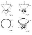
- Figure 3a shows a UV lamp assembly 1 b in the side view with a two-part, round Lamp base 2 and a reflector body 3 made of glass.
- the outlet opening of the reflector body 3 for UV radiation is covered with a filter disk 4.
- the reflector body 3 a reflector neck 3a, which has a bayonet lock directly to the lamp base 2 is connected.
- 3 Crescent-shaped recesses 3b arranged for UV radiation.
- here covers the Filter disc 4, the reflector body 3 completely, so that no opening remains.
- On the lamp base 2 are a spring 5a and 5b screws for mounting the UV lamp assembly 1 b in a tanning device available.
- FIG. 3b shows the UV lamp arrangement 1b of FIG. 3a in a further side view, however turned by 90 degrees. It can be seen that the two parts of the two-piece lamp base 2 are connected by rivets or screw 2a.
- FIG. 3c shows the UV lamp arrangement 1b of FIGS. 3a and 3b in plan view.
- FIG. 3d shows the UV lamp arrangement 1b of FIGS. 3a to 3c in three-dimensional form View.
- Figure 3e shows the detail C of Figure 3d in an enlarged view.
- the bayonet lock clearly visible between the reflector body 3 and the lamp cap 2.
- openings 2b in the lamp base 2 are present, through which on both sides of the lamp cap 2 electrical connections of a not visible here, in the reflector body 3 arranged UV burner are performed.
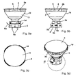
- Figure 4a shows a UV lamp assembly 1 c in the side view with a two-part, round Lamp base 2 and a reflector body 3 made of glass, wherein only one half of the lamp cap 2 is shown.
- the outlet opening of the reflector body 3 for UV radiation is with a filter disc 4 covered.
- the reflector body 3 has a reflector neck 3a, which is connected via a bayonet lock directly to the lamp base 2.
- the filter disk 4 covers the reflector body third completely, so that no opening remains.
- On the lamp base 2 are a spring 5a and retaining screws 5b for installing the UV lamp assembly 1 c in a tanning device available.
- FIG. 4b shows the UV lamp arrangement 1c from FIG. 4a in a further side view, however turned by 90 degrees. It is the interior of the lamp cap 2 can be seen.
- FIG. 4c shows the UV lamp arrangement 1c from FIGS. 4a and 4b in plan view.
- FIG. 4 d shows the UV lamp arrangement 1 c from FIGS. 4 a to 4 c in three-dimensional form View.
- Figure 4e shows the detail E of Figure 4d in an enlarged view.
- the reflector neck 3a clearly visible with molded there nubs 3c for the bayonet lock.
- the openings 2b in the lamp base 2 can be seen, through which on both sides of the lamp cap 2 electrical connections of a not visible here, in the reflector body 3 arranged UV burner are performed.
- a leaf spring 7 is present, which presses the reflector body 3 upwards and so fixed the bayonet lock.
- Figure 4f shows the detail D of Figure 4b in an enlarged view. Again, the openings 2b in the lamp base 2 recognizable, through which on both sides of the lamp cap 2 electrical connections of a not visible here, arranged in the reflector body 3 UV burner be guided. To fix the reflector neck 3a in the lamp base 2 is the leaf spring 7 exists, which presses the reflector body 3 upwards and so the bayonet lock fixed.
- Figure 5a shows a UV lamp assembly 1 d in the side view with a two-piece, round Lamp base 2 and a reflector body 3 made of glass.
- the outlet opening of the reflector body 3 for UV radiation is covered with a filter disk 4.
- the reflector body 3 a reflector neck 3a, on which a configured as a ring further component 3d is appropriate.
- the configured as a ring component 3d has nubs 3c (see Fig. 5e) and is connected via a bayonet lock directly to the lamp base 2.
- On the lamp base 2 are a spring 5a and 5b screws to install the UV lamp assembly 1d in a tanning device available.
- FIG. 5b shows the UV lamp arrangement 1d from FIG. 5a in a further side view, however turned by 90 degrees. It can be seen that the two parts of the two-piece lamp base 2 are connected by rivets or screw 2a.
- FIG. 5c shows the UV lamp arrangement 1d from FIGS. 5a and 5b in plan view.
- FIG. 5 d shows the UV lamp arrangement 1 d from FIGS. 5 a to 5 c in three-dimensional form View.
- Figure 5e shows the detail F of Figure 5d in an enlarged view.
- the reflector neck 3a is in the region 3e with the component 3d configured as a ring firmly connected by means of an adhesive, not shown here.
- openings 2b in Lamp base 2 present, through which on both sides of the lamp base 2 electrical Connected to a not visible here, guided in the reflector body 3 UV burner out become.
- Figure 6a shows a UV lamp assembly 1 e in three-dimensional view with a one-piece elongated, on the short sides rounded lamp base 2 and a reflector body. 3 of glass.
- the outlet opening of the reflector body 3 for UV radiation is provided with a filter disk 4 covered.
- the reflector body 3 has a reflector neck 3a, on which a mounted as a ring further component 3d is attached and a bayonet lock is directly connected to the lamp base 2.
- Make two trained as gripping arms 8 strap is a mechanical connection between the reflector body 3 and the ring 3d.
- Am Lamp base 2 are a spring 5a for installation of the UV lamp assembly 1 e in a tanning device available.
- Figure 6b shows a UV lamp assembly of Fig. 6a in three-dimensional view with a one-piece, oblong, rounded at the sides lamp base 2 without a reflector body 3 of glass.
- the burner 9 in the lamp base 2 with the leaf spring 7, which presses the reflector body 3 upwards and thus fixes the bayonet closure.
- the side openings 2b can be seen, through which on both sides of the lamp cap 2, the electrical connections 11 of the seen here, in the reflector body arranged UV burner 9 are guided.
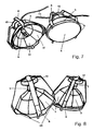
- Figures 7 and 8 show three-dimensional views of two UV lamp assemblies 1, wherein each having a lamp cap 2 and a concave reflector body 3.
- the right of the two UV lamp assemblies of Fig. 7 shows a filter disk 4 on the reflector body 3.
- Die on the other hand, the left-hand of the two UV lamp arrangements from FIG. 7 does not show a filter disk 4 am Reflector body 3, so that disposed within the cavity of the reflector body 3 UV burner 9 becomes visible.
- the holder of reflector body 3 via four gripping arms 8, which are formed from bent metal strips and a simple dismantling of reflector body 3 and filter disc 4 and thus allow replacement of the UV burner 9.
- the reflector body 3 is configured with facets 3f.
- FIG. 9 shows a UV lamp arrangement 1 in a three-dimensional view, in which the gripping arms 8 are formed so that they the base 2 at the reflector outlet opening with spring tension press against the reflector 3.
- FIG. 10 shows a lamp arrangement 1, in which a base 2 with two gripping arms 8 on the reflector body 3 is held.
- the gripping arms 8 are designed so that they the base. 2 clamp against the reflector neck 3a or configured as a ring member 3d.
- FIG. 11 shows a lamp arrangement 1, in three-dimensional representation, in which the gripper arms 8, similarly as in Fig. 9, are designed as Klammem, the base against the reflector. 3 Press, with the gripping arms 8 engage in the reflector opening.
- FIG. 12 shows a lamp arrangement 1, in which a base 2 with two gripping arms 8 on the reflector body 3 is held.
- the gripping arms 8 are formed as a U-profile bracket, the Base 2 against the reflector neck 3a or configured as a ring component 3d clamps.
Abstract
Description
Die Erfindung betrifft eine UV-Lampenanordnung mit einem Lampensockel, mit einem am Lampensockel angeordneten, konkaven Reflektorkörper, mit einem innerhalb der Kavität des Reflektorkörpers und am Lampensockel angeordneten UV-Brenner, insbesondere mit einer Filterscheibe, die eine Austrittsöffnung des Reflektorkörpers für UV-Strahlung bedeckt. Die Erfindung betrifft weiterhin eine Verwendung dieser UV-Lampenanordnung.The invention relates to a UV lamp assembly with a lamp base, with one on the lamp base arranged, concave reflector body, with a within the cavity of the reflector body and arranged on the lamp base UV burner, in particular with a filter disc, which covers an outlet opening of the reflector body for UV radiation. The invention further relates to a use of this UV lamp assembly.
Derartige Lampenanordnungen sind aus der WO 97/32158 für Besonnungsgeräte bekannt. In einem Glaskolben, der innen mit einer Reflexionsschicht belegt ist, ist hier eine Quecksilberdampfhochdrucklampe stehend als Bräunungsstrahler angeordnet. Der Glaskolben wird von einem UV-Filter abgeschlossen. Dabei ist der Filter und/oder der Bräunungsstrahler austauschbar. Nachdem bei der hier offenbarten Lampenanordnung der Glaskolben zum Bräunungsstrahler und zum UV-Filter mittels Dichtungen luftdicht abgeschlossen werden soll, um den Glaskoben evakuieren zu können, erweist sich ein Wechsel des UV-Filters oder des Strahlers als problematisch bezüglich einer erneuten Abdichtung.Such lamp arrangements are known from WO 97/32158 for tanning equipment. In a glass bulb, which is covered inside with a reflection layer, here is a high pressure mercury vapor lamp standing arranged as a tanning spot. The glass bulb is from completed a UV filter. The filter and / or the tanning lamp is interchangeable. After in the lamp assembly disclosed herein, the glass bulb for tanning and to seal the UV filter by means of seals airtight to the glass top To be able to evacuate, a change of the UV filter or the radiator proves to be problematic regarding a new seal.
Die EP 301 208 offenbart einen Bajonettsockel für eine Lampe oder einen Reflektor, wobei der Bajonettverschluss den Lampensockel in einer Lampenfassung fixiert. Zwischen dem Reflektor und dem Bajonettsockel sind Steck- oder Klemmverbindungen offenbart, wobei der Reflektor vom Sockel lösbar sein kann.EP 301 208 discloses a bayonet socket for a lamp or a reflector, wherein the Bayonet catch the lamp base fixed in a lamp holder. Between the reflector and the bayonet socket plug or clamp connections are disclosed, wherein the reflector can be detached from the socket.
Die DE 20106885U1 offenbart ebenfalls eine Lampe mit einem Bajonettsockel, wobei der Bajonettverschluss den Sockel in einer Lampenfassung fixiert. Die Lampe weist einen vom Bajonettsockel abschraubbaren Lampenkolben auf. DE 20106885U1 also discloses a lamp with a bayonet base, wherein the bayonet closure fixed the base in a lamp socket. The lamp has one of the bayonet socket unscrewable lamp bulb on.
Es ist nun Aufgabe der Erfindung, ein UV-Lampensystem der eingangs genannten Art bereitzustellen, bei dem der Austausch des Bräunungsstrahlers einfacher und problemloser ausgeführt werden kann, wobei die Weiterverwendung der übrigen Teile des UV-Lampensystems weiterhin ermöglicht wird.It is an object of the invention to provide a UV lamp system of the type mentioned, in which the replacement of the tanning lamp easier and easier to run can be, with the further use of the remaining parts of the UV lamp system continues is possible.
Die Aufgabe wird dadurch gelöst, dass der Reflektorkörper über einen Bajonettverschluss lösbar mit dem Lampensockel verbunden ist. Durch eine derartige Ausgestaltung der Lampenanordnung kann der Reflektorkörper ggf. inklusive einer Filterglasscheibe durch einen einfachen Handgriff abgenommen werden, so dass der Brenner direkt zugänglich ist. Es ist nun möglich, entweder den Brenner allein auszutauschen oder diesen inklusive Sockel zu ersetzen. Der Reflektorkörper und eine ggf. daran angeordnete Filterscheibe können weiterverwendet werden.The object is achieved in that the reflector body via a bayonet lock solvable connected to the lamp base. By such a configuration of the lamp assembly If necessary, the reflector body including a filter glass by a simple Handle are removed, so that the burner is directly accessible. It is now possible Either replace the burner alone or replace it with the base. The reflector body and a filter disc optionally arranged thereon can be reused.
Die Aufgabe wird auch dadurch gelöst, dass der Reflektorkörper über mindestens zwei Greifarme mit dem Lampensockel verbunden ist. Eine derartige Ausgestaltung ermöglicht wie der Bajonettverschluss einen einfachen Austausch des UV-Brenners bei dessen Ausfall und eine Wiederverwendung aller restlichen Bauteile wie Reflektor, Filterglasscheibe, Lampensockel, elektrischen Anschlüssen und Greifarmen.The object is also achieved in that the reflector body via at least two gripping arms connected to the lamp base. Such a configuration allows as the Bayonet lock a simple replacement of the UV burner in case of failure and a Reuse of all remaining components such as reflector, filter glass, lamp base, electrical connections and gripping arms.
Die erfindungsgemäße Lösung ist für alle Lampenanordnungen, die für optische Strahlung vorgesehen sind, geeignet. Hierzu kann optische Strahlung mit einem Strahler erzeugt werden. Hat der Strahler sein Maximum im VIS oder IR, handelt es sich um eine VIS- oder IR-Lampenanordnung mit einem VIS- oder IR-Brenner, deren Reflektor vorzugsweise eine VISoder IR-reflektierende Schicht aufweist. Der Reflektor kann dabei ggf. für UV-Strahlung durchlässig sein. Insbesondere ist die Lampenanordnung für UV-Strahlung vorgesehen, die mit einem UV-Strahler erzeugt wird.The solution according to the invention is intended for all lamp arrangements intended for optical radiation are suitable. For this purpose, optical radiation can be generated with a radiator. Has the radiator maximum in the VIS or IR, it is a VIS or IR lamp assembly with a VIS or IR burner whose reflector is preferably a VIS or Has IR-reflective layer. If necessary, the reflector can be transparent to UV radiation be. In particular, the lamp assembly for UV radiation is provided with a UV emitter is generated.
Dabei hat es sich bewährt, wenn der Reflektorkörper einen Reflektorhals aufweist und der Reflektorhals über den Bajonettverschluss lösbar mit dem Lampensockel verbunden ist, oder aber wenn der Reflektorkörper an der Strahleröffnung des Reflektors über einen Bajonettverschluss oder mit Greifarmenlösbar mit dem Lampensockel verbunden ist.It has proven useful if the reflector body has a reflector neck and the reflector neck is detachably connected to the lamp base via the bayonet lock, or else if the reflector body at the radiator opening of the reflector via a bayonet closure or releasably connected to the lamp base with gripper arms.
Es ist bevorzugt, den Reflektorkörper aus Glas, Glaskeramik, Keramik oder Metall zu bilden. Der Reflektorkörper weist dabei vorzugsweise eine UV-Strahlung reflektierende Beschichtung auf. It is preferred to form the reflector body of glass, glass ceramic, ceramic or metal. The reflector body preferably has a coating which reflects UV radiation on.
Insbesondere hat es sich bewährt, wenn der Reflektorkörper aus Glas oder Glaskeramik gebildet ist und seine Beschichtung für Infrarotstrahlung durchlässig ist. So wird Wärme aus dem Reflektorkörper abtransportiert und eine Kühlung des Reflektorkörpers kann unterbleiben.In particular, it has proven useful if the reflector body is formed from glass or glass ceramic is and its coating is transparent to infrared radiation. This is how heat gets out of Reflector removed and cooling of the reflector body can be omitted.
Es hat sich bewährt, wenn der Reflektorkörper Facetten aufweist.
Weiterhin hat es sich bewährt, wenn die UV-Strahlung reflektierende Beschichtung des Reflektorkörpers
mindestens ein Metalloxid enthält.It has proven useful if the reflector body has facets.
Furthermore, it has proven useful if the UV radiation-reflecting coating of the reflector body contains at least one metal oxide.
Es ist von Vorteil, wenn die Filterscheibe mit dem Reflektorkörper durch einen elastischen Kleber verbunden ist. Vorzugsweise wird ein Kleber auf Silikonbasis gewähltIt is advantageous if the filter disc with the reflector body by an elastic adhesive connected is. Preferably, a silicone-based adhesive is chosen
Dabei ist bevorzugt, dass die Filterscheibe derart mit dem Reflektorkörper verbunden ist, dass
Öffnungen verbleiben, über welche ein Luftaustausch zwischen einem Raum außerhalb und
dem Raum innerhalb des Reflektorkörpers erfolgen kann.
Dabei hat es sich bewährt, wenn der Reflektorkörper im Bereich der Austrittsöffnung an seinem
Umfang mindestens eine halbmondförmige Aussparung aufweist.It is preferred that the filter disk is connected to the reflector body in such a way that openings remain, via which an air exchange between a space outside and the space inside the reflector body can take place.
It has proven useful if the reflector body has at least one half-moon-shaped recess in the region of the outlet opening on its circumference.
Es ist aber genauso möglich, dass die Filterscheibe die Austrittsöffnung des Reflektorkörpers vollständig verschließt.But it is just as possible that the filter disc, the outlet opening of the reflector body completely closes.
Es hat sich bewährt, wenn der Lampensockel aus Keramik, Kunststoff oder Metall gebildet ist. Dabei wird Keramik besonders bevorzugt, da es nicht nur hoch temperaturbeständig sondern auch elektrisch isolierend ist, so dass die elektrischen Anschlüsse für den UV-Brenner nicht gesondert elektrisch vom Sockel isoliert werden müssen.It has proven useful if the lamp cap made of ceramic, plastic or metal is formed. In this case, ceramic is particularly preferred, since it is not only high temperature resistant but is also electrically insulating, so that the electrical connections for the UV burner is not separately electrically isolated from the base.
Es hat sich weiterhin als günstig erwiesen, wenn der Reflektorkörper aus Borosilikatglas oder Kalk-Natron-Glas gebildet ist.It has also proved to be favorable when the reflector body made of borosilicate glass or Lime-soda-glass is formed.
Besonders bevorzugt ist es, wenn der Reflektorhals und der Reflektorkörper aus demselben Material und in einem Stück ausgebildet sind, wobei am Reflektorhals Noppen angeformt sind, so dass er direkt mit dem Lampensockel verbunden werden kann.It is particularly preferred if the reflector neck and the reflector body of the same Material and are formed in one piece, wherein the reflector neck nubs are formed, so that it can be connected directly to the lamp base.
Es ist aber genauso möglich, dass der Reflektorhals und der Reflektorkörper aus demselben
Material und in einem Stück ausgebildet sind, wobei der Reflektorhals mit einem als Ring ausgestaltetem
weiteren Bauteil verbunden ist, an welchem Noppen angeformt sind, so dass der
Ring direkt mit dem Lampensockel verbunden werden kann. Dabei kann der Ring aus Metall,
Kunststoff oder Keramik gebildet sein.
Es hat sich bewährt, wenn der Ring mit dem Reflektorhals mittels Glaslot oder Kleber verbunden
ist oder der Ring auf den Reflektorhals aufgeschrumpft ist. Hierzu sind sowohl Ein- als auch
Mehrkomponentenkleber geeignet. Insbesondere ist es bevorzugt, wenn der Kleber ein anorganischer
Kleber ist, wie beispielsweise Sauereisenzement oder wenn der Kleber auf Silikonbasis
ist.But it is equally possible that the reflector neck and the reflector body are formed of the same material and in one piece, wherein the reflector neck is connected to a configured as a ring further component, are formed on which nubs, so that the ring is directly connected to the lamp cap can be. In this case, the ring may be formed of metal, plastic or ceramic.
It has proven useful if the ring is connected to the reflector neck by means of glass solder or adhesive or the ring is shrunk onto the reflector neck. Both single- and multi-component adhesives are suitable for this purpose. In particular, it is preferred if the adhesive is an inorganic adhesive such as acid rice cement or if the adhesive is silicone based.
Besonders günstig ist es, wenn die Greifarme aus gebogenem Draht oder gebogenen Blechstreifen gebildet sind.It is particularly favorable when the gripping arms made of bent wire or bent metal strips are formed.
Es ist bevorzugt, einen Metallhalogenidstrahler als UV-Brenner einzusetzen.
Dabei weist der UV-Brenner vorzugsweise einen Lampenkolben aus Kieselglas sowie elektrische
Kontakte auf, die entweder an einer Seite oder an sich gegenüber liegenden Seiten des
Lampenkolbens durch diesen gasdicht hindurchgeführt sind.It is preferable to use a metal halide lamp as a UV burner.
In this case, the UV burner preferably has a lamp bulb made of silica glass and electrical contacts, which are passed through this gas-tight either on one side or on opposite sides of the lamp envelope.
Eine Verwendung der erfindungsgemäßen UV-Lampenanordnung ohne Zwangskühlung in einem Leistungsbereich von 100W bis 300W ist ideal.A use of the UV lamp assembly according to the invention without forced cooling in one Power range from 100W to 300W is ideal.
Besonders bevorzugt ist dabei die Verwendung von mindestens einer UV-Lampenanordnung in
einem Bräunungsgerät.
Dabei hat es sich besonders bewährt, wenn die mindestens eine UV-Lampenanordnung mittels
zwei Halteschrauben, die in einem Abstand von 25 - 27mm zueinander angeordnet sind, in dem
Bräunungsgerät montiert ist.Particularly preferred is the use of at least one UV lamp assembly in a tanning device.
It has proven particularly useful if the at least one UV lamp assembly by means of two retaining screws, which are arranged at a distance of 25 - 27mm to each other, is mounted in the tanning device.
Weiterhin hat es sich bewährt, wenn die mindestens eine UV-Lampenanordnung mittels zwei Halteschrauben, die in einem Abstand von 29 - 31mm zueinander angeordnet sind, in dem Bräunungsgerät montiert ist.Furthermore, it has proven useful if the at least one UV lamp assembly by means of two Retaining screws, which are arranged at a distance of 29 - 31mm to each other, in the Tanning device is mounted.
Die Figuren 1a bis 12 sollen die erfindungsgemäße UV-Lampenanordnung beispielhaft erläutem. Dabei betreffen Figuren 1 bis 6b Ausführungen mit Bajonettverschluss, und Figuren 7 bis 12 Ausführungen mit Greifarmen. So zeigt/zeigen:
- Fig. 1a bis 1e
- eine UV-Lampenanordnung mit rechteckigem Lampensockel in unterschiedlichen Ansichten;
- Fig. 2a bis 2e
- eine weitere UV-Lampenanordnung mit rundem Lampensockel in unterschiedlichen Ansichten;
- Fig. 3a bis 3e
- eine weitere UV-Lampenanordnung mit rundem Lampensockel in unterschiedlichen Ansichten;
- Fig. 4a bis 4f
- eine weitere UV-Lampenanordnung mit rundem Lampensockel in unterschiedlichen Ansichten, wobei nur eine Hälfte des Lampensockels dargestellt ist;
- Fig. 5a bis 5e
- eine weitere UV-Lampenanordnung mit rundem Lampensockel in unterschiedlichen Ansichten;
- Fig. 6a bis 6b
- eine weitere UV-Lampenanordnung mit länglichen Lampensockel mit und ohne Reflektor;
- Fig. 7
- eine dreidimensionale Ansicht von zwei UV-Lampenanordnungen mit je vier Greifarmen aus gebogenen Blechstreifen;
- Fig. 8
- eine weitere dreidimensionale Ansicht der UV-Lampenanordnungen aus Fig. 7;
- Fig. 9
- eine Ausführung bei der die Greifarme so ausgebildet sind, dass sie den Sockel an der Strahlereintrittsöffnung des Reflektors mit Federspannkraft gegen den Reflektor drücken;
- Fig. 10
- eine Lampenanordnung, bei der ein Sockel mit zwei Greifarmen am Reflektorkörper gehalten wird. Dabei sind die Greifarme so ausgebildet, dass sie den Sockel gegen den Reflektorhals klemmen;
- Fig. 11
- eine Ausführung bei der die Greifarme als Klammern ausgebildet sind, die den Sockel gegen den Reflektor drücken, wobei die Greifarme in die Reflektoröffnung eingreifen;
- Fig. 12
- eine Lampenanordnung, bei der ein Sockel mit zwei Greifarmen am Reflektorkörper gehalten wird. Dabei sind die Greifarme so ausgebildet, dass sie den Sockel gegen den Reflektorhals klemmen.
- Fig. 1a to 1e
- a UV lamp assembly with rectangular lamp base in different views;
- Fig. 2a to 2e
- another UV lamp assembly with round lamp base in different views;
- Fig. 3a to 3e
- another UV lamp assembly with round lamp base in different views;
- Fig. 4a to 4f
- a further UV lamp assembly with round lamp base in different views, wherein only one half of the lamp cap is shown;
- Fig. 5a to 5e
- another UV lamp assembly with round lamp base in different views;
- Fig. 6a to 6b
- Another UV lamp assembly with elongated lamp base with and without reflector;
- Fig. 7
- a three-dimensional view of two UV lamp assemblies with four gripping arms of bent metal strips;
- Fig. 8
- another three-dimensional view of the UV lamp assemblies of Fig. 7;
- Fig. 9
- an embodiment in which the gripping arms are formed so that they press the base at the radiator inlet opening of the reflector with spring tension against the reflector;
- Fig. 10
- a lamp assembly in which a base with two gripping arms is held on the reflector body. The gripping arms are designed so that they clamp the base against the reflector neck;
- Fig. 11
- an embodiment in which the gripping arms are formed as brackets which press the base against the reflector, wherein the gripping arms engage in the reflector opening;
- Fig. 12
- a lamp assembly in which a base with two gripping arms is held on the reflector body. The gripping arms are designed so that they clamp the base against the reflector neck.
Figur 1a zeigt eine UV-Lampenanordnung 1 in der Seitenansicht mit einem zweiteiligen, rechteckigen
Lampensockel 2 und einem Reflektorkörper 3 aus Glas. Die Austrittsöffnung des Reflektorkörpers
3 für UV-Strahlung ist mit einer Filterscheibe 4 bedeckt. Weiterhin weist der Reflektorkörper
3 einen Reflektorhals 3a auf, der über einen Bajonettverschluss direkt mit dem
Lampensockel 2 verbunden ist. Außerdem sind im Bereich der Austrittsöffnung des Reflektorkörpers
3 für UV-Strahlung halbmondförmige Aussparungen 3b derart angeordnet, dass Öffnungen
6 einen Luftaustausch zum Raum im Reflektorkörper 3 ermöglichen. Am Lampensockel
2 sind eine Feder 5a sowie Halteschrauben 5b zum Einbau der UV-Lampenanordnung 1 in ein
Bräunungsgerät vorhanden.Figure 1a shows a
Figur 1b zeigt die UV-Lampenanordnung 1 aus Fig. 1 in einer weiteren Seitenansicht, allerdings
um 90° gedreht. Es ist zu erkennen, dass die beiden Teile des zweiteiligen Lampensockels 2
durch Nieten oder Verschraubungen 2a verbunden sind.FIG. 1b shows the
Figur 1c zeigt die UV-Lampenanordnung 1 aus den Figuren 1a und 1b in der Draufsicht.FIG. 1c shows the
Figur 1d zeigt die UV-Lampenanordnung 1 aus den Figuren 1a bis 1c in dreidimensionaler Ansicht.FIG. 1d shows the
Figur 1e zeigt den Ausschnitt A aus Figur 1d in vergrößerter Darstellung. Dabei ist der Bajonettverschluss
zwischen dem Reflektorkörper 3 und dem Lampensockel 2 deutlich zu erkennen.
Weiterhin sind Öffnungen 2b im Lampensockel 2 vorhanden, durch welche zu beiden Seiten
des Lampensockels 2 elektrische Anschlüsse eines hier nicht zu sehenden, im Reflektorkörper
3 angeordneten UV-Brenners geführt werden.Figure 1e shows the detail A of Figure 1d in an enlarged view. Here is the bayonet lock
clearly visible between the
Figur 2a zeigt eine weitere UV-Lampenanordnung 1a in der Seitenansicht mit einem zweiteiligen,
runden Lampensockel 2 und einem Reflektorkörper 3 aus Glas. Die Austrittsöffnung des
Reflektorkörpers 3 für UV-Strahlung ist mit einer Filterscheibe 4 bedeckt. Weiterhin weist der
Reflektorkörper 3 einen Reflektorhals 3a auf, der über einen Bajonettverschluss direkt mit dem
Lampensockel 2 verbunden ist. Außerdem sind im Bereich der Austrittsöffnung des Reflektorkörpers
3 für UV-Strahlung halbmondförmige Aussparungen 3b angeordnet. Allerdings bedeckt
hier die Filterscheibe 4 den Reflektorkörper 3 vollständig, so dass keine Öffnung verbleibt. Am
Lampensockel 2 sind eine Feder 5a sowie Halteschrauben 5b zum Einbau der UV-Lampenanordnung
1a in ein Bräunungsgerät vorhanden. FIG. 2 a shows a side view of a further
Figur 2b zeigt die UV-Lampenanordnung 1a aus Fig. 2a in einer weiteren Seitenansicht, allerdings
um 90° gedreht. Es ist zu erkennen, dass die beiden Teile des zweiteiligen Lampensockels
2 durch Nieten oder Verschraubungen 2a verbunden sind.FIG. 2b shows the
Figur 2c zeigt die UV-Lampenanordnung 1a aus den Figuren 2a und 2b in der Draufsicht.FIG. 2c shows the
Figur 2d zeigt die UV-Lampenanordnung 1a aus den Figuren 2a bis 2c in dreidimensionaler
Ansicht.FIG. 2d shows the
Figur 2e zeigt den Ausschnitt B aus Figur 2d in vergrößerter Darstellung. Dabei ist der Bajonettverschluss
zwischen dem Reflektorkörper 3 und dem Lampensockel 2 deutlich zu erkennen.
Weiterhin sind Öffnungen 2b im Lampensockel 2 vorhanden, durch welche zu beiden Seiten
des Lampensockels 2 elektrische Anschlüsse eines hier nicht zu sehenden, im Reflektorkörper
3 angeordneten UV-Brenners geführt werden.Figure 2e shows the detail B of Figure 2d in an enlarged view. Here is the bayonet lock
clearly visible between the
Figur 3a zeigt eine UV-Lampenanordnung 1 b in der Seitenansicht mit einem zweiteiligen, runden
Lampensockel 2 und einem Reflektorkörper 3 aus Glas. Die Austrittsöffnung des Reflektorkörpers
3 für UV-Strahlung ist mit einer Filterscheibe 4 bedeckt. Weiterhin weist der Reflektorkörper
3 einen Reflektorhals 3a auf, der über einen Bajonettverschluss direkt mit dem Lampensockel
2 verbunden ist. Außerdem sind im Bereich der Austrittsöffnung des Reflektorkörpers 3
für UV-Strahlung halbmondförmige Aussparungen 3b angeordnet. Allerdings bedeckt hier die
Filterscheibe 4 den Reflektorkörper 3 vollständig, so dass keine Öffnung verbleibt. Am Lampensockel
2 sind eine Feder 5a sowie Halteschrauben 5b zum Einbau der UV-Lampenanordnung
1 b in ein Bräunungsgerät vorhanden.Figure 3a shows a
Figur 3b zeigt die UV-Lampenanordnung 1 b aus Fig. 3a in einer weiteren Seitenansicht, allerdings
um 90° gedreht. Es ist zu erkennen, dass die beiden Teile des zweiteiligen Lampensockels
2 durch Nieten oder Verschraubungen 2a verbunden sind.FIG. 3b shows the
Figur 3c zeigt die UV-Lampenanordnung 1 b aus den Figuren 3a und 3b in der Draufsicht.FIG. 3c shows the
Figur 3d zeigt die UV-Lampenanordnung 1 b aus den Figuren 3a bis 3c in dreidimensionaler
Ansicht. FIG. 3d shows the
Figur 3e zeigt den Ausschnitt C aus Figur 3d in vergrößerter Darstellung. Dabei ist der Bajonettverschluss
zwischen dem Reflektorkörper 3 und dem Lampensockel 2 deutlich zu erkennen.
Weiterhin sind Öffnungen 2b im Lampensockel 2 vorhanden, durch welche zu beiden Seiten
des Lampensockels 2 elektrische Anschlüsse eines hier nicht zu sehenden, im Reflektorkörper
3 angeordneten UV-Brenners geführt werden.Figure 3e shows the detail C of Figure 3d in an enlarged view. Here is the bayonet lock
clearly visible between the
Figur 4a zeigt eine UV-Lampenanordnung 1 c in der Seitenansicht mit einem zweiteiligen, runden
Lampensockel 2 und einem Reflektorkörper 3 aus Glas, wobei nur eine Hälfte des Lampensockels
2 dargestellt ist. Die Austrittsöffnung des Reflektorkörpers 3 für UV-Strahlung ist mit
einer Filterscheibe 4 bedeckt. Weiterhin weist der Reflektorkörper 3 einen Reflektorhals 3a auf,
der über einen Bajonettverschluss direkt mit dem Lampensockel 2 verbunden ist. Außerdem
sind im Bereich der Austrittsöffnung des Reflektorkörpers 3 für UV-Strahlung halbmondförmige
Aussparungen 3b angeordnet. Allerdings bedeckt hier die Filterscheibe 4 den Reflektorkörper 3
vollständig, so dass keine Öffnung verbleibt. Am Lampensockel 2 sind eine Feder 5a sowie Halteschrauben
5b zum Einbau der UV-Lampenanordnung 1 c in ein Bräunungsgerät vorhanden.Figure 4a shows a
Figur 4b zeigt die UV-Lampenanordnung 1 c aus Fig. 4a in einer weiteren Seitenansicht, allerdings
um 90° gedreht. Es ist das Innere des Lampensockels 2 zu erkennen.FIG. 4b shows the
Figur 4c zeigt die UV-Lampenanordnung 1 c aus den Figuren 4a und 4b in der Draufsicht.FIG. 4c shows the
Figur 4d zeigt die UV-Lampenanordnung 1 c aus den Figuren 4a bis 4c in dreidimensionaler
Ansicht.FIG. 4 d shows the
Figur 4e zeigt den Ausschnitt E aus Figur 4d in vergrößerter Darstellung. Dabei ist der Reflektorhals
3a mit daran angeformten Noppen 3c für den Bajonettverschluss deutlich zu erkennen.
Weiterhin sind die Öffnungen 2b im Lampensockel 2 erkennbar, durch welche zu beiden Seiten
des Lampensockels 2 elektrische Anschlüsse eines hier nicht zu sehenden, im Reflektorkörper
3 angeordneten UV-Brenners geführt werden. Zur Fixierung des Reflektorhalses 3a im Lampensockel
2 ist eine Blattfeder 7 vorhanden, die den Reflektorkörper 3 nach oben drückt und so
den Bajonettverschluss fixiert.Figure 4e shows the detail E of Figure 4d in an enlarged view. Here is the
Figur 4f zeigt den Ausschnitt D aus Figur 4b in vergrößerter Darstellung. Wieder sind die Öffnungen
2b im Lampensockel 2 erkennbar, durch welche zu beiden Seiten des Lampensockels
2 elektrische Anschlüsse eines hier nicht zu sehenden, im Reflektorkörper 3 angeordneten UV-Brenners
geführt werden. Zur Fixierung des Reflektorhalses 3a im Lampensockel 2 ist die Blattfeder
7 vorhanden, die den Reflektorkörper 3 nach oben drückt und so den Bajonettverschluss
fixiert.Figure 4f shows the detail D of Figure 4b in an enlarged view. Again, the
Figur 5a zeigt eine UV-Lampenanordnung 1 d in der Seitenansicht mit einem zweiteiligen, runden
Lampensockel 2 und einem Reflektorkörper 3 aus Glas. Die Austrittsöffnung des Reflektorkörpers
3 für UV-Strahlung ist mit einer Filterscheibe 4 bedeckt. Weiterhin weist der Reflektorkörper
3 einen Reflektorhals 3a auf, an welchem ein als Ring ausgestaltetes weiteres Bauteil 3d
angebracht ist. Das als Ring ausgestaltete Bauteil 3d weist dabei Noppen 3c auf ( siehe Fig. 5e)
und ist über einen Bajonettverschluss direkt mit dem Lampensockel 2 verbunden. Außerdem
sind im Bereich der Austrittsöffnung des Reflektorkörpers 3 für UV-Strahlung halbmondförmige
Aussparungen 3b derart angeordnet, dass Öffnungen 6 einen Luftaustausch zum Raum im Reflektorkörper
3 ermöglichen. Am Lampensockel 2 sind eine Feder 5a sowie Halteschrauben 5b
zum Einbau der UV-Lampenanordnung 1d in ein Bräunungsgerät vorhanden.Figure 5a shows a
Figur 5b zeigt die UV-Lampenanordnung 1 d aus Fig. 5a in einer weiteren Seitenansicht, allerdings
um 90° gedreht. Es ist zu erkennen, dass die beiden Teile des zweiteiligen Lampensockels
2 durch Nieten oder Verschraubungen 2a verbunden sind.FIG. 5b shows the
Figur 5c zeigt die UV-Lampenanordnung 1d aus den Figuren 5a und 5b in der Draufsicht.FIG. 5c shows the
Figur 5d zeigt die UV-Lampenanordnung 1 d aus den Figuren 5a bis 5c in dreidimensionaler
Ansicht.FIG. 5 d shows the
Figur 5e zeigt den Ausschnitt F aus Figur 5d in vergrößerter Darstellung. Dabei ist der Bajonettverschluss
zwischen dem als Ring ausgestaltetem Bauteil 3d und dem Lampensockel 2 deutlich
zu erkennen. Der Reflektorhals 3a ist mit dem als Ring ausgestaltetem Bauteil 3d im Bereich 3e
mittels eines hier nicht dargestellten Klebers fest verbunden. Weiterhin sind Öffnungen 2b im
Lampensockel 2 vorhanden, durch welche zu beiden Seiten des Lampensockels 2 elektrische
Anschlüsse eines hier nicht zu sehenden, im Reflektorkörper 3 angeordneten UV-Brenners geführt
werden.Figure 5e shows the detail F of Figure 5d in an enlarged view. Here is the bayonet lock
between the designed as a
Figur 6a zeigt eine UV-Lampenanordnung 1 e in dreidimensionaler Ansicht mit einem einteiligen
länglichen, an den kurzen Seiten abgerundeten Lampensockel 2 und einem Reflektorkörper 3
aus Glas. Die Austrittsöffnung des Reflektorkörpers 3 für UV-Strahlung ist mit einer Filterscheibe
4 bedeckt. Weiterhin weist der Reflektorkörper 3 einen Reflektorhals 3a auf, an welchem ein
als Ring ausgestaltetes weiteres Bauteil 3d angebracht ist und über einen Bajonettverschluss
direkt mit dem Lampensockel 2 verbunden ist. Zwei als Greifarme 8 ausgebildete Bügel stellen
hier eine mechanische Verbindung zwischen dem Reflektorkörper 3 und dem Ring 3d dar. Am
Lampensockel 2 sind eine Feder 5a zum Einbau der UV-Lampenanordnung 1 e in ein Bräunungsgerät
vorhanden.Figure 6a shows a
Figur 6b zeigt eine UV-Lampenanordnung aus Fig. 6a in dreidimensionaler Ansicht mit einem
einteiligen, länglichen, an den Seiten abgerundeten Lampensockel 2 ohne einen Reflektorkörper
3 aus Glas. Deutlich zu erkennen ist der Brenner 9 in dem Lampensockel 2 mit der Blattfeder
7, die den Reflektorkörper 3 nach oben drückt und so den Bajonettverschluss fixiert. Im
Lampensockel 2 sind die seitlichen Öffnungen 2b erkennbar, durch welche zu beiden Seiten
des Lampensockels 2 die elektrischen Anschlüsse 11 des hier zu sehenden, im Reflektorkörper
angeordneten UV-Brenners 9 geführt werden.Figure 6b shows a UV lamp assembly of Fig. 6a in three-dimensional view with a
one-piece, oblong, rounded at the
Figuren 7 und 8 zeigen dreidimensionale Ansichten von zwei UV-Lampenanordnungen 1, wobei
jede einen Lampensockel 2 und einen konkaven Reflektorkörper 3 aufweist. Die rechte der beiden
UV-Lampenanordnungen aus Fig. 7 zeigt eine Filterscheibe 4 am Reflektorkörper 3. Die
linke der beiden UV-Lampenanordnungen aus Fig. 7 zeigt dagegen keine Filterscheibe 4 am
Reflektorkörper 3, so dass der innerhalb der Kavität des Reflektorkörpers 3 angeordnete UV-Brenner
9 sichtbar wird. Die Halterung von Reflektorkörper 3 erfolgt über je vier Greifarme 8,
die aus gebogenen Blechstreifen gebildet sind und eine einfache Demontage von Reflektorkörper
3 und Filterscheibe 4 und somit einen Austausch des UV-Brenners 9 ermöglichen. Der Reflektorkörper
3 ist mit Facetten 3f ausgestaltet. Die linke UV-Lampenanordnung 1 aus Fig. 8
zeigt weiterhin am Reflektorkörper 3 halbmondförmige Aussparungen 3b, die nach Montage
einer Filterscheibe einen Luftaustausch zwischen dem Raum innerhalb des Reflektorkörpers 3
und dem Raum außerhalb des Reflektorkörpers 3 ermöglichen. Der elektrische Anschluss des
UV-Brenners 9 mit dem Lampensockel 2 erfolgt über die Fassung 10 mit den elektrischen Anschlussdrähten
11.Figures 7 and 8 show three-dimensional views of two
Figur 9 zeigt eine UV-Lampenanordnung 1 in dreidimensionaler Ansicht, in der die Greifarme 8
so ausgebildet sind, dass sie den Sockel 2 an der Reflektoraustrittsöffnung mit Federspannkraft
gegen den Reflektor 3 drücken. FIG. 9 shows a
Figur 10 zeigt eine Lampenanordnung 1, bei der ein Sockel 2 mit zwei Greifarmen 8 am Reflektorkörper
3 gehalten wird. Dabei sind die Greifarme 8 so ausgebildet, dass sie den Sockel 2
gegen den Reflektorhals 3a oder das als Ring ausgestaltete Bauteil 3d klemmen.FIG. 10 shows a
Figur 11 zeigt eine Lampenanordnung 1, in dreidimensonaler Darstellung, bei der die Greifarme
8, ähnlich wie in Fig. 9, als Klammem ausgebildet sind, die den Sockel gegen den Reflektor 3
drücken, wobei die Greifarme 8 in die Reflektoröffnung eingreifen.FIG. 11 shows a
Figur 12 zeigt eine Lampenanordnung 1, bei der ein Sockel 2 mit zwei Greifarmen 8 am Reflektorkörper
3 gehalten wird. Dabei sind die Greifarme 8 als U-Profil-Klammer ausgebildet, die den
Sockel 2 gegen den Reflektorhals 3a oder ein als Ring ausgestaltetes Bauteil 3d klemmt.FIG. 12 shows a
Claims (14)
Priority Applications (1)
| Application Number | Priority Date | Filing Date | Title |
|---|---|---|---|
| PL04021097T PL1515085T3 (en) | 2003-09-15 | 2004-09-06 | UV lamp assembly and use thereof |
Applications Claiming Priority (4)
| Application Number | Priority Date | Filing Date | Title |
|---|---|---|---|
| DE2003142876 DE10342876B4 (en) | 2003-09-15 | 2003-09-15 | UV lamp assembly and its use |
| DE10342876 | 2003-09-15 | ||
| DE10346131 | 2003-10-01 | ||
| DE10346131A DE10346131A1 (en) | 2003-10-01 | 2003-10-01 | UV lamp assembly and its use |
Publications (3)
| Publication Number | Publication Date |
|---|---|
| EP1515085A2 true EP1515085A2 (en) | 2005-03-16 |
| EP1515085A3 EP1515085A3 (en) | 2013-07-24 |
| EP1515085B1 EP1515085B1 (en) | 2015-06-24 |
Family
ID=34137328
Family Applications (1)
| Application Number | Title | Priority Date | Filing Date |
|---|---|---|---|
| EP04021097.3A Not-in-force EP1515085B1 (en) | 2003-09-15 | 2004-09-06 | UV lamp assembly and use thereof |
Country Status (4)
| Country | Link |
|---|---|
| EP (1) | EP1515085B1 (en) |
| ES (1) | ES2546011T3 (en) |
| HU (1) | HUE025563T2 (en) |
| PL (1) | PL1515085T3 (en) |
Cited By (2)
| Publication number | Priority date | Publication date | Assignee | Title |
|---|---|---|---|---|
| EP1793159A1 (en) * | 2005-12-05 | 2007-06-06 | Park, Shi-heung | Infrared lamp apparatus |
| CN104456445A (en) * | 2013-09-13 | 2015-03-25 | 海洋王(东莞)照明科技有限公司 | Lamp connecting device and illuminating lamp |
Citations (4)
| Publication number | Priority date | Publication date | Assignee | Title |
|---|---|---|---|---|
| GB1475663A (en) * | 1975-10-24 | 1977-06-01 | Practical Prod Mfg Ltd | Reflector and bulbholder assembly |
| DE8907132U1 (en) * | 1988-11-04 | 1989-07-20 | Megalit, Z.I Du Breuil, Saint Florent Sur Cher, Fr | |
| DE9001445U1 (en) * | 1990-02-08 | 1990-04-12 | Hoffmeister-Leuchten Gmbh & Co Kg, 5880 Luedenscheid, De | |
| EP1306106A2 (en) * | 2001-10-24 | 2003-05-02 | Heraeus Noblelight GmbH | Tanning module with a housing |
Family Cites Families (1)
| Publication number | Priority date | Publication date | Assignee | Title |
|---|---|---|---|---|
| DE445204C (en) * | 1927-06-01 | Hedwig Koertge Geb Stutzer | Fastening device for reflectors |
-
2004
- 2004-09-06 HU HUE04021097A patent/HUE025563T2/en unknown
- 2004-09-06 PL PL04021097T patent/PL1515085T3/en unknown
- 2004-09-06 ES ES04021097.3T patent/ES2546011T3/en active Active
- 2004-09-06 EP EP04021097.3A patent/EP1515085B1/en not_active Not-in-force
Patent Citations (4)
| Publication number | Priority date | Publication date | Assignee | Title |
|---|---|---|---|---|
| GB1475663A (en) * | 1975-10-24 | 1977-06-01 | Practical Prod Mfg Ltd | Reflector and bulbholder assembly |
| DE8907132U1 (en) * | 1988-11-04 | 1989-07-20 | Megalit, Z.I Du Breuil, Saint Florent Sur Cher, Fr | |
| DE9001445U1 (en) * | 1990-02-08 | 1990-04-12 | Hoffmeister-Leuchten Gmbh & Co Kg, 5880 Luedenscheid, De | |
| EP1306106A2 (en) * | 2001-10-24 | 2003-05-02 | Heraeus Noblelight GmbH | Tanning module with a housing |
Cited By (3)
| Publication number | Priority date | Publication date | Assignee | Title |
|---|---|---|---|---|
| EP1793159A1 (en) * | 2005-12-05 | 2007-06-06 | Park, Shi-heung | Infrared lamp apparatus |
| CN104456445A (en) * | 2013-09-13 | 2015-03-25 | 海洋王(东莞)照明科技有限公司 | Lamp connecting device and illuminating lamp |
| CN104456445B (en) * | 2013-09-13 | 2019-04-16 | 海洋王(东莞)照明科技有限公司 | Connecting device for lamp and illuminator |
Also Published As
| Publication number | Publication date |
|---|---|
| EP1515085B1 (en) | 2015-06-24 |
| ES2546011T3 (en) | 2015-09-17 |
| PL1515085T3 (en) | 2015-11-30 |
| EP1515085A3 (en) | 2013-07-24 |
| HUE025563T2 (en) | 2016-03-29 |
Similar Documents
| Publication | Publication Date | Title |
|---|---|---|
| DE102008052869B4 (en) | Luminaire with LED mounting rail | |
| DE3033688C2 (en) | ||
| DE202007016530U1 (en) | Electric light | |
| DE2906605A1 (en) | LIGHT BULB WITH TIGHTLY ENCLOSED REFLECTOR HOUSING | |
| EP1515085B1 (en) | UV lamp assembly and use thereof | |
| DE102016121481A1 (en) | Lamp with control gear and arrangement with air conditioning | |
| DE10342876B4 (en) | UV lamp assembly and its use | |
| EP0075839B1 (en) | Electric lamp | |
| EP0121819B1 (en) | Reflector lamp | |
| EP2020678A2 (en) | Electric lamp with an external piston and a fitted lamp | |
| EP0513758B1 (en) | Baking oven, particularly built-in baking oven | |
| DE19855265A1 (en) | Electric lamp and lighting device with such an electric lamp | |
| EP1435636A2 (en) | Lighting unit | |
| EP1009012A1 (en) | Electric lamp | |
| DE2926531C2 (en) | Headlight with a reflector made of plastic | |
| DE10122878B4 (en) | Lighting device for ovens | |
| DE202007008956U1 (en) | Lamp holder for a vehicle lamp | |
| EP0611916B1 (en) | Lamp for microwave ovens | |
| EP1055873A2 (en) | Lamp | |
| DE19509112A1 (en) | Compact fluorescent lighting unit | |
| EP0301236A2 (en) | Spray-sealed projector | |
| EP1662248A2 (en) | Weathering apparatus radiation-source holder | |
| EP1329931B1 (en) | Compact low pressure discharge lamp | |
| DE102013104150B4 (en) | Lamp holder and method for its assembly | |
| EP1045198A2 (en) | Socket for halogen bulb |
Legal Events
| Date | Code | Title | Description |
|---|---|---|---|
| PUAI | Public reference made under article 153(3) epc to a published international application that has entered the european phase |
Free format text: ORIGINAL CODE: 0009012 |
|
| 17P | Request for examination filed |
Effective date: 20040909 |
|
| AK | Designated contracting states |
Kind code of ref document: A2 Designated state(s): AT BE BG CH CY CZ DE DK EE ES FI FR GB GR HU IE IT LI LU MC NL PL PT RO SE SI SK TR |
|
| AX | Request for extension of the european patent |
Extension state: AL HR LT LV MK |
|
| PUAL | Search report despatched |
Free format text: ORIGINAL CODE: 0009013 |
|
| AK | Designated contracting states |
Kind code of ref document: A3 Designated state(s): AT BE BG CH CY CZ DE DK EE ES FI FR GB GR HU IE IT LI LU MC NL PL PT RO SE SI SK TR |
|
| AX | Request for extension of the european patent |
Extension state: AL HR LT LV MK |
|
| RIC1 | Information provided on ipc code assigned before grant |
Ipc: A61N 5/06 20060101ALI20130619BHEP Ipc: F21V 17/10 20060101AFI20130619BHEP |
|
| AKX | Designation fees paid |
Designated state(s): AT BE BG CH CY CZ DE DK EE ES FI FR GB GR HU IE IT LI LU MC NL PL PT RO SE SI SK TR |
|
| 17Q | First examination report despatched |
Effective date: 20140613 |
|
| GRAP | Despatch of communication of intention to grant a patent |
Free format text: ORIGINAL CODE: EPIDOSNIGR1 |
|
| RIC1 | Information provided on ipc code assigned before grant |
Ipc: A61N 5/06 20060101ALI20150304BHEP Ipc: F21V 17/14 20060101ALI20150304BHEP Ipc: F21V 19/00 20060101ALI20150304BHEP Ipc: F21V 17/10 20060101AFI20150304BHEP Ipc: F21V 27/02 20060101ALI20150304BHEP Ipc: F21V 17/06 20060101ALI20150304BHEP |
|
| INTG | Intention to grant announced |
Effective date: 20150324 |
|
| GRAS | Grant fee paid |
Free format text: ORIGINAL CODE: EPIDOSNIGR3 |
|
| GRAA | (expected) grant |
Free format text: ORIGINAL CODE: 0009210 |
|
| AK | Designated contracting states |
Kind code of ref document: B1 Designated state(s): AT BE BG CH CY CZ DE DK EE ES FI FR GB GR HU IE IT LI LU MC NL PL PT RO SE SI SK TR |
|
| REG | Reference to a national code |
Ref country code: GB Ref legal event code: FG4D Free format text: NOT ENGLISH |
|
| REG | Reference to a national code |
Ref country code: CH Ref legal event code: EP |
|
| REG | Reference to a national code |
Ref country code: AT Ref legal event code: REF Ref document number: 733072 Country of ref document: AT Kind code of ref document: T Effective date: 20150715 |
|
| REG | Reference to a national code |
Ref country code: IE Ref legal event code: FG4D Free format text: LANGUAGE OF EP DOCUMENT: GERMAN |
|
| REG | Reference to a national code |
Ref country code: DE Ref legal event code: R096 Ref document number: 502004014936 Country of ref document: DE |
|
| REG | Reference to a national code |
Ref country code: ES Ref legal event code: FG2A Ref document number: 2546011 Country of ref document: ES Kind code of ref document: T3 Effective date: 20150917 |
|
| REG | Reference to a national code |
Ref country code: NL Ref legal event code: FP |
|
| PG25 | Lapsed in a contracting state [announced via postgrant information from national office to epo] |
Ref country code: FI Free format text: LAPSE BECAUSE OF FAILURE TO SUBMIT A TRANSLATION OF THE DESCRIPTION OR TO PAY THE FEE WITHIN THE PRESCRIBED TIME-LIMIT Effective date: 20150624 |
|
| PG25 | Lapsed in a contracting state [announced via postgrant information from national office to epo] |
Ref country code: BG Free format text: LAPSE BECAUSE OF FAILURE TO SUBMIT A TRANSLATION OF THE DESCRIPTION OR TO PAY THE FEE WITHIN THE PRESCRIBED TIME-LIMIT Effective date: 20150924 Ref country code: GR Free format text: LAPSE BECAUSE OF FAILURE TO SUBMIT A TRANSLATION OF THE DESCRIPTION OR TO PAY THE FEE WITHIN THE PRESCRIBED TIME-LIMIT Effective date: 20150925 |
|
| REG | Reference to a national code |
Ref country code: PL Ref legal event code: T3 |
|
| PG25 | Lapsed in a contracting state [announced via postgrant information from national office to epo] |
Ref country code: EE Free format text: LAPSE BECAUSE OF FAILURE TO SUBMIT A TRANSLATION OF THE DESCRIPTION OR TO PAY THE FEE WITHIN THE PRESCRIBED TIME-LIMIT Effective date: 20150624 |
|
| PG25 | Lapsed in a contracting state [announced via postgrant information from national office to epo] |
Ref country code: PT Free format text: LAPSE BECAUSE OF FAILURE TO SUBMIT A TRANSLATION OF THE DESCRIPTION OR TO PAY THE FEE WITHIN THE PRESCRIBED TIME-LIMIT Effective date: 20151026 Ref country code: SK Free format text: LAPSE BECAUSE OF FAILURE TO SUBMIT A TRANSLATION OF THE DESCRIPTION OR TO PAY THE FEE WITHIN THE PRESCRIBED TIME-LIMIT Effective date: 20150624 Ref country code: RO Free format text: LAPSE BECAUSE OF NON-PAYMENT OF DUE FEES Effective date: 20150624 Ref country code: CZ Free format text: LAPSE BECAUSE OF FAILURE TO SUBMIT A TRANSLATION OF THE DESCRIPTION OR TO PAY THE FEE WITHIN THE PRESCRIBED TIME-LIMIT Effective date: 20150624 |
|
| REG | Reference to a national code |
Ref country code: HU Ref legal event code: AG4A Ref document number: E025563 Country of ref document: HU Ref country code: DE Ref legal event code: R097 Ref document number: 502004014936 Country of ref document: DE |
|
| PG25 | Lapsed in a contracting state [announced via postgrant information from national office to epo] |
Ref country code: MC Free format text: LAPSE BECAUSE OF FAILURE TO SUBMIT A TRANSLATION OF THE DESCRIPTION OR TO PAY THE FEE WITHIN THE PRESCRIBED TIME-LIMIT Effective date: 20150624 Ref country code: DK Free format text: LAPSE BECAUSE OF FAILURE TO SUBMIT A TRANSLATION OF THE DESCRIPTION OR TO PAY THE FEE WITHIN THE PRESCRIBED TIME-LIMIT Effective date: 20150624 Ref country code: LU Free format text: LAPSE BECAUSE OF FAILURE TO SUBMIT A TRANSLATION OF THE DESCRIPTION OR TO PAY THE FEE WITHIN THE PRESCRIBED TIME-LIMIT Effective date: 20150906 |
|
| PLBE | No opposition filed within time limit |
Free format text: ORIGINAL CODE: 0009261 |
|
| REG | Reference to a national code |
Ref country code: CH Ref legal event code: PL |
|
| STAA | Information on the status of an ep patent application or granted ep patent |
Free format text: STATUS: NO OPPOSITION FILED WITHIN TIME LIMIT |
|
| GBPC | Gb: european patent ceased through non-payment of renewal fee |
Effective date: 20150924 |
|
| 26N | No opposition filed |
Effective date: 20160329 |
|
| REG | Reference to a national code |
Ref country code: IE Ref legal event code: MM4A |
|
| REG | Reference to a national code |
Ref country code: FR Ref legal event code: ST Effective date: 20160531 |
|
| PG25 | Lapsed in a contracting state [announced via postgrant information from national office to epo] |
Ref country code: LI Free format text: LAPSE BECAUSE OF NON-PAYMENT OF DUE FEES Effective date: 20150930 Ref country code: IE Free format text: LAPSE BECAUSE OF NON-PAYMENT OF DUE FEES Effective date: 20150906 Ref country code: GB Free format text: LAPSE BECAUSE OF NON-PAYMENT OF DUE FEES Effective date: 20150924 Ref country code: CH Free format text: LAPSE BECAUSE OF NON-PAYMENT OF DUE FEES Effective date: 20150930 |
|
| PG25 | Lapsed in a contracting state [announced via postgrant information from national office to epo] |
Ref country code: SI Free format text: LAPSE BECAUSE OF FAILURE TO SUBMIT A TRANSLATION OF THE DESCRIPTION OR TO PAY THE FEE WITHIN THE PRESCRIBED TIME-LIMIT Effective date: 20150624 Ref country code: FR Free format text: LAPSE BECAUSE OF NON-PAYMENT OF DUE FEES Effective date: 20150930 |
|
| REG | Reference to a national code |
Ref country code: AT Ref legal event code: MM01 Ref document number: 733072 Country of ref document: AT Kind code of ref document: T Effective date: 20150906 |
|
| PG25 | Lapsed in a contracting state [announced via postgrant information from national office to epo] |
Ref country code: AT Free format text: LAPSE BECAUSE OF NON-PAYMENT OF DUE FEES Effective date: 20150906 |
|
| PG25 | Lapsed in a contracting state [announced via postgrant information from national office to epo] |
Ref country code: SE Free format text: LAPSE BECAUSE OF FAILURE TO SUBMIT A TRANSLATION OF THE DESCRIPTION OR TO PAY THE FEE WITHIN THE PRESCRIBED TIME-LIMIT Effective date: 20150624 Ref country code: CY Free format text: LAPSE BECAUSE OF FAILURE TO SUBMIT A TRANSLATION OF THE DESCRIPTION OR TO PAY THE FEE WITHIN THE PRESCRIBED TIME-LIMIT Effective date: 20150624 |
|
| PG25 | Lapsed in a contracting state [announced via postgrant information from national office to epo] |
Ref country code: TR Free format text: LAPSE BECAUSE OF FAILURE TO SUBMIT A TRANSLATION OF THE DESCRIPTION OR TO PAY THE FEE WITHIN THE PRESCRIBED TIME-LIMIT Effective date: 20150624 |
|
| REG | Reference to a national code |
Ref country code: DE Ref legal event code: R082 Ref document number: 502004014936 Country of ref document: DE Representative=s name: BRAND, NORMEN, DR. RER. NAT., DE Ref country code: DE Ref legal event code: R082 Ref document number: 502004014936 Country of ref document: DE Representative=s name: EULER, MATTHIAS, DR., DE Ref country code: DE Ref legal event code: R082 Ref document number: 502004014936 Country of ref document: DE Representative=s name: BRAND, NORMEN, DIPL.-CHEM. UNIV. DR. RER. NAT., DE |
|
| REG | Reference to a national code |
Ref country code: DE Ref legal event code: R082 Ref document number: 502004014936 Country of ref document: DE Representative=s name: BRAND, NORMEN, DR. RER. NAT., DE Ref country code: DE Ref legal event code: R082 Ref document number: 502004014936 Country of ref document: DE Representative=s name: BRAND, NORMEN, DIPL.-CHEM. UNIV. DR. RER. NAT., DE |
|
| PGFP | Annual fee paid to national office [announced via postgrant information from national office to epo] |
Ref country code: DE Payment date: 20200925 Year of fee payment: 17 Ref country code: NL Payment date: 20200925 Year of fee payment: 17 |
|
| PGFP | Annual fee paid to national office [announced via postgrant information from national office to epo] |
Ref country code: IT Payment date: 20200922 Year of fee payment: 17 Ref country code: PL Payment date: 20200828 Year of fee payment: 17 Ref country code: BE Payment date: 20200925 Year of fee payment: 17 |
|
| PGFP | Annual fee paid to national office [announced via postgrant information from national office to epo] |
Ref country code: ES Payment date: 20201120 Year of fee payment: 17 Ref country code: HU Payment date: 20201021 Year of fee payment: 17 |
|
| REG | Reference to a national code |
Ref country code: DE Ref legal event code: R119 Ref document number: 502004014936 Country of ref document: DE |
|
| REG | Reference to a national code |
Ref country code: NL Ref legal event code: MM Effective date: 20211001 |
|
| REG | Reference to a national code |
Ref country code: BE Ref legal event code: MM Effective date: 20210930 |
|
| PG25 | Lapsed in a contracting state [announced via postgrant information from national office to epo] |
Ref country code: NL Free format text: LAPSE BECAUSE OF NON-PAYMENT OF DUE FEES Effective date: 20211001 |
|
| PG25 | Lapsed in a contracting state [announced via postgrant information from national office to epo] |
Ref country code: HU Free format text: LAPSE BECAUSE OF NON-PAYMENT OF DUE FEES Effective date: 20210907 Ref country code: DE Free format text: LAPSE BECAUSE OF NON-PAYMENT OF DUE FEES Effective date: 20220401 Ref country code: BE Free format text: LAPSE BECAUSE OF NON-PAYMENT OF DUE FEES Effective date: 20210930 |
|
| REG | Reference to a national code |
Ref country code: ES Ref legal event code: FD2A Effective date: 20221026 |
|
| PG25 | Lapsed in a contracting state [announced via postgrant information from national office to epo] |
Ref country code: IT Free format text: LAPSE BECAUSE OF NON-PAYMENT OF DUE FEES Effective date: 20210906 |
|
| PG25 | Lapsed in a contracting state [announced via postgrant information from national office to epo] |
Ref country code: ES Free format text: LAPSE BECAUSE OF NON-PAYMENT OF DUE FEES Effective date: 20210907 |
|
| PG25 | Lapsed in a contracting state [announced via postgrant information from national office to epo] |
Ref country code: PL Free format text: LAPSE BECAUSE OF NON-PAYMENT OF DUE FEES Effective date: 20210906 |