EP1515085A2 - Ensemble lampe UV et son utilisation - Google Patents
Ensemble lampe UV et son utilisation Download PDFInfo
- Publication number
- EP1515085A2 EP1515085A2 EP04021097A EP04021097A EP1515085A2 EP 1515085 A2 EP1515085 A2 EP 1515085A2 EP 04021097 A EP04021097 A EP 04021097A EP 04021097 A EP04021097 A EP 04021097A EP 1515085 A2 EP1515085 A2 EP 1515085A2
- Authority
- EP
- European Patent Office
- Prior art keywords
- lamp
- reflector
- reflector body
- base
- arrangement
- Prior art date
- Legal status (The legal status is an assumption and is not a legal conclusion. Google has not performed a legal analysis and makes no representation as to the accuracy of the status listed.)
- Granted
Links
- 0 CC=CCC1(CC1)*1=CCC=C1 Chemical compound CC=CCC1(CC1)*1=CCC=C1 0.000 description 1
Images


Classifications
-
- F—MECHANICAL ENGINEERING; LIGHTING; HEATING; WEAPONS; BLASTING
- F21—LIGHTING
- F21V—FUNCTIONAL FEATURES OR DETAILS OF LIGHTING DEVICES OR SYSTEMS THEREOF; STRUCTURAL COMBINATIONS OF LIGHTING DEVICES WITH OTHER ARTICLES, NOT OTHERWISE PROVIDED FOR
- F21V17/00—Fastening of component parts of lighting devices, e.g. shades, globes, refractors, reflectors, filters, screens, grids or protective cages
- F21V17/10—Fastening of component parts of lighting devices, e.g. shades, globes, refractors, reflectors, filters, screens, grids or protective cages characterised by specific fastening means or way of fastening
- F21V17/14—Bayonet-type fastening
-
- F—MECHANICAL ENGINEERING; LIGHTING; HEATING; WEAPONS; BLASTING
- F21—LIGHTING
- F21V—FUNCTIONAL FEATURES OR DETAILS OF LIGHTING DEVICES OR SYSTEMS THEREOF; STRUCTURAL COMBINATIONS OF LIGHTING DEVICES WITH OTHER ARTICLES, NOT OTHERWISE PROVIDED FOR
- F21V17/00—Fastening of component parts of lighting devices, e.g. shades, globes, refractors, reflectors, filters, screens, grids or protective cages
- F21V17/06—Fastening of component parts of lighting devices, e.g. shades, globes, refractors, reflectors, filters, screens, grids or protective cages the fastening being onto or by the lampholder
-
- A—HUMAN NECESSITIES
- A61—MEDICAL OR VETERINARY SCIENCE; HYGIENE
- A61N—ELECTROTHERAPY; MAGNETOTHERAPY; RADIATION THERAPY; ULTRASOUND THERAPY
- A61N5/00—Radiation therapy
- A61N5/06—Radiation therapy using light
- A61N5/0613—Apparatus adapted for a specific treatment
- A61N5/0614—Tanning
-
- F—MECHANICAL ENGINEERING; LIGHTING; HEATING; WEAPONS; BLASTING
- F21—LIGHTING
- F21V—FUNCTIONAL FEATURES OR DETAILS OF LIGHTING DEVICES OR SYSTEMS THEREOF; STRUCTURAL COMBINATIONS OF LIGHTING DEVICES WITH OTHER ARTICLES, NOT OTHERWISE PROVIDED FOR
- F21V19/00—Fastening of light sources or lamp holders
- F21V19/006—Fastening of light sources or lamp holders of point-like light sources, e.g. incandescent or halogen lamps, with screw-threaded or bayonet base
-
- F—MECHANICAL ENGINEERING; LIGHTING; HEATING; WEAPONS; BLASTING
- F21—LIGHTING
- F21V—FUNCTIONAL FEATURES OR DETAILS OF LIGHTING DEVICES OR SYSTEMS THEREOF; STRUCTURAL COMBINATIONS OF LIGHTING DEVICES WITH OTHER ARTICLES, NOT OTHERWISE PROVIDED FOR
- F21V27/00—Cable-stowing arrangements structurally associated with lighting devices, e.g. reels
- F21V27/02—Cable inlets
Definitions
- the invention relates to a UV lamp assembly with a lamp base, with one on the lamp base arranged, concave reflector body, with a within the cavity of the reflector body and arranged on the lamp base UV burner, in particular with a filter disc, which covers an outlet opening of the reflector body for UV radiation.
- the invention further relates to a use of this UV lamp assembly.
- Such lamp arrangements are known from WO 97/32158 for tanning equipment.
- a glass bulb which is covered inside with a reflection layer, here is a high pressure mercury vapor lamp standing arranged as a tanning spot.
- the glass bulb is from completed a UV filter.
- the filter and / or the tanning lamp is interchangeable.
- the glass bulb for tanning and to seal the UV filter by means of seals airtight to the glass top
- a change of the UV filter or the radiator proves to be problematic regarding a new seal.
- EP 301 208 discloses a bayonet socket for a lamp or a reflector, wherein the Bayonet catch the lamp base fixed in a lamp holder. Between the reflector and the bayonet socket plug or clamp connections are disclosed, wherein the reflector can be detached from the socket.
- DE 20106885U1 also discloses a lamp with a bayonet base, wherein the bayonet closure fixed the base in a lamp socket.
- the lamp has one of the bayonet socket unscrewable lamp bulb on.
- the reflector body via a bayonet lock solvable connected to the lamp base.
- the reflector body including a filter glass by a simple Handle are removed, so that the burner is directly accessible. It is now possible Either replace the burner alone or replace it with the base.
- the reflector body and a filter disc optionally arranged thereon can be reused.
- the object is also achieved in that the reflector body via at least two gripping arms connected to the lamp base.
- Such a configuration allows as the Bayonet lock a simple replacement of the UV burner in case of failure and a Reuse of all remaining components such as reflector, filter glass, lamp base, electrical connections and gripping arms.
- optical radiation can be generated with a radiator.
- the radiator maximum in the VIS or IR it is a VIS or IR lamp assembly with a VIS or IR burner whose reflector is preferably a VIS or Has IR-reflective layer.
- the reflector can be transparent to UV radiation be.
- the lamp assembly for UV radiation is provided with a UV emitter is generated.
- the reflector body has a reflector neck and the reflector neck is detachably connected to the lamp base via the bayonet lock, or else if the reflector body at the radiator opening of the reflector via a bayonet closure or releasably connected to the lamp base with gripper arms.
- the reflector body preferably has a coating which reflects UV radiation on.
- the reflector body is formed from glass or glass ceramic is and its coating is transparent to infrared radiation. This is how heat gets out of Reflector removed and cooling of the reflector body can be omitted.
- the reflector body has facets. Furthermore, it has proven useful if the UV radiation-reflecting coating of the reflector body contains at least one metal oxide.
- the filter disc with the reflector body by an elastic adhesive connected is advantageous if the filter disc with the reflector body by an elastic adhesive connected.
- a silicone-based adhesive is chosen
- the filter disk is connected to the reflector body in such a way that openings remain, via which an air exchange between a space outside and the space inside the reflector body can take place. It has proven useful if the reflector body has at least one half-moon-shaped recess in the region of the outlet opening on its circumference.
- the lamp cap made of ceramic, plastic or metal is formed.
- ceramic is particularly preferred, since it is not only high temperature resistant but is also electrically insulating, so that the electrical connections for the UV burner is not separately electrically isolated from the base.
- the reflector neck and the reflector body of the same Material are formed in one piece, wherein the reflector neck nubs are formed, so that it can be connected directly to the lamp base.
- the reflector neck and the reflector body are formed of the same material and in one piece, wherein the reflector neck is connected to a configured as a ring further component, are formed on which nubs, so that the ring is directly connected to the lamp cap can be.
- the ring may be formed of metal, plastic or ceramic. It has proven useful if the ring is connected to the reflector neck by means of glass solder or adhesive or the ring is shrunk onto the reflector neck. Both single- and multi-component adhesives are suitable for this purpose. In particular, it is preferred if the adhesive is an inorganic adhesive such as acid rice cement or if the adhesive is silicone based.
- the UV burner preferably has a lamp bulb made of silica glass and electrical contacts, which are passed through this gas-tight either on one side or on opposite sides of the lamp envelope.
- a use of the UV lamp assembly according to the invention without forced cooling in one Power range from 100W to 300W is ideal.
- At least one UV lamp assembly in a tanning device. It has proven particularly useful if the at least one UV lamp assembly by means of two retaining screws, which are arranged at a distance of 25 - 27mm to each other, is mounted in the tanning device.
- the at least one UV lamp assembly by means of two Retaining screws, which are arranged at a distance of 29 - 31mm to each other, in the Tanning device is mounted.
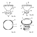
- Figure 1a shows a UV lamp assembly 1 in the side view with a two-part, rectangular Lamp base 2 and a reflector body 3 made of glass.
- the outlet opening of the reflector body 3 for UV radiation is covered with a filter disk 4.
- the reflector body 3 a reflector neck 3a, which has a bayonet lock directly to the Lamp base 2 is connected.
- crescent-shaped recesses 3b arranged such that openings 6 allow an exchange of air to the space in the reflector body 3.
- On the lamp base 2 are a spring 5a and retaining screws 5b for installation of the UV lamp assembly 1 in a Tanning device available.
- FIG. 1b shows the UV lamp arrangement 1 from FIG. 1 in a further side view, however turned by 90 degrees. It can be seen that the two parts of the two-part lamp cap 2 are connected by rivets or screw 2a.
- FIG. 1c shows the UV lamp arrangement 1 from FIGS. 1a and 1b in plan view.
- FIG. 1d shows the UV lamp arrangement 1 from FIGS. 1a to 1c in a three-dimensional view.
- Figure 1e shows the detail A of Figure 1d in an enlarged view.
- the bayonet lock clearly visible between the reflector body 3 and the lamp cap 2.
- openings 2b in the lamp base 2 are present, through which on both sides of the lamp cap 2 electrical connections of a not visible here, in the reflector body 3 arranged UV burner are performed.
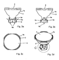
- FIG. 2 a shows a side view of a further UV lamp arrangement 1 a with a two-part, round lamp base 2 and a reflector body 3 made of glass.
- the exit opening of the Reflector body 3 for UV radiation is covered with a filter disk 4.
- the Reflector body 3 a reflector neck 3a, which has a bayonet directly with the Lamp base 2 is connected.
- the filter disk 4 covers the region of the outlet opening of the reflector body 3 for UV radiation crescent-shaped recesses 3b arranged.
- the filter disk 4 covers here the filter disk 4, the reflector body 3 completely, so that no opening remains.
- At the Lamp base 2 are a spring 5a and 5b screws for mounting the UV lamp assembly 1a present in a tanning device.
- FIG. 2b shows the UV lamp arrangement 1a from FIG. 2a in a further side view, however turned by 90 degrees. It can be seen that the two parts of the two-piece lamp base 2 are connected by rivets or screw 2a.
- FIG. 2c shows the UV lamp arrangement 1a from FIGS. 2a and 2b in plan view.
- FIG. 2d shows the UV lamp arrangement 1a from FIGS. 2a to 2c in three-dimensional form View.
- Figure 2e shows the detail B of Figure 2d in an enlarged view.
- the bayonet lock clearly visible between the reflector body 3 and the lamp cap 2.
- openings 2b in the lamp base 2 are present, through which on both sides of the lamp cap 2 electrical connections of a not visible here, in the reflector body 3 arranged UV burner are performed.
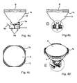
- Figure 3a shows a UV lamp assembly 1 b in the side view with a two-part, round Lamp base 2 and a reflector body 3 made of glass.
- the outlet opening of the reflector body 3 for UV radiation is covered with a filter disk 4.
- the reflector body 3 a reflector neck 3a, which has a bayonet lock directly to the lamp base 2 is connected.
- 3 Crescent-shaped recesses 3b arranged for UV radiation.
- here covers the Filter disc 4, the reflector body 3 completely, so that no opening remains.
- On the lamp base 2 are a spring 5a and 5b screws for mounting the UV lamp assembly 1 b in a tanning device available.
- FIG. 3b shows the UV lamp arrangement 1b of FIG. 3a in a further side view, however turned by 90 degrees. It can be seen that the two parts of the two-piece lamp base 2 are connected by rivets or screw 2a.
- FIG. 3c shows the UV lamp arrangement 1b of FIGS. 3a and 3b in plan view.
- FIG. 3d shows the UV lamp arrangement 1b of FIGS. 3a to 3c in three-dimensional form View.
- Figure 3e shows the detail C of Figure 3d in an enlarged view.
- the bayonet lock clearly visible between the reflector body 3 and the lamp cap 2.
- openings 2b in the lamp base 2 are present, through which on both sides of the lamp cap 2 electrical connections of a not visible here, in the reflector body 3 arranged UV burner are performed.
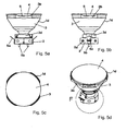
- Figure 4a shows a UV lamp assembly 1 c in the side view with a two-part, round Lamp base 2 and a reflector body 3 made of glass, wherein only one half of the lamp cap 2 is shown.
- the outlet opening of the reflector body 3 for UV radiation is with a filter disc 4 covered.
- the reflector body 3 has a reflector neck 3a, which is connected via a bayonet lock directly to the lamp base 2.
- the filter disk 4 covers the reflector body third completely, so that no opening remains.
- On the lamp base 2 are a spring 5a and retaining screws 5b for installing the UV lamp assembly 1 c in a tanning device available.
- FIG. 4b shows the UV lamp arrangement 1c from FIG. 4a in a further side view, however turned by 90 degrees. It is the interior of the lamp cap 2 can be seen.
- FIG. 4c shows the UV lamp arrangement 1c from FIGS. 4a and 4b in plan view.
- FIG. 4 d shows the UV lamp arrangement 1 c from FIGS. 4 a to 4 c in three-dimensional form View.
- Figure 4e shows the detail E of Figure 4d in an enlarged view.
- the reflector neck 3a clearly visible with molded there nubs 3c for the bayonet lock.
- the openings 2b in the lamp base 2 can be seen, through which on both sides of the lamp cap 2 electrical connections of a not visible here, in the reflector body 3 arranged UV burner are performed.
- a leaf spring 7 is present, which presses the reflector body 3 upwards and so fixed the bayonet lock.
- Figure 4f shows the detail D of Figure 4b in an enlarged view. Again, the openings 2b in the lamp base 2 recognizable, through which on both sides of the lamp cap 2 electrical connections of a not visible here, arranged in the reflector body 3 UV burner be guided. To fix the reflector neck 3a in the lamp base 2 is the leaf spring 7 exists, which presses the reflector body 3 upwards and so the bayonet lock fixed.
- Figure 5a shows a UV lamp assembly 1 d in the side view with a two-piece, round Lamp base 2 and a reflector body 3 made of glass.
- the outlet opening of the reflector body 3 for UV radiation is covered with a filter disk 4.
- the reflector body 3 a reflector neck 3a, on which a configured as a ring further component 3d is appropriate.
- the configured as a ring component 3d has nubs 3c (see Fig. 5e) and is connected via a bayonet lock directly to the lamp base 2.
- On the lamp base 2 are a spring 5a and 5b screws to install the UV lamp assembly 1d in a tanning device available.
- FIG. 5b shows the UV lamp arrangement 1d from FIG. 5a in a further side view, however turned by 90 degrees. It can be seen that the two parts of the two-piece lamp base 2 are connected by rivets or screw 2a.
- FIG. 5c shows the UV lamp arrangement 1d from FIGS. 5a and 5b in plan view.
- FIG. 5 d shows the UV lamp arrangement 1 d from FIGS. 5 a to 5 c in three-dimensional form View.
- Figure 5e shows the detail F of Figure 5d in an enlarged view.
- the reflector neck 3a is in the region 3e with the component 3d configured as a ring firmly connected by means of an adhesive, not shown here.
- openings 2b in Lamp base 2 present, through which on both sides of the lamp base 2 electrical Connected to a not visible here, guided in the reflector body 3 UV burner out become.
- Figure 6a shows a UV lamp assembly 1 e in three-dimensional view with a one-piece elongated, on the short sides rounded lamp base 2 and a reflector body. 3 of glass.
- the outlet opening of the reflector body 3 for UV radiation is provided with a filter disk 4 covered.
- the reflector body 3 has a reflector neck 3a, on which a mounted as a ring further component 3d is attached and a bayonet lock is directly connected to the lamp base 2.
- Make two trained as gripping arms 8 strap is a mechanical connection between the reflector body 3 and the ring 3d.
- Am Lamp base 2 are a spring 5a for installation of the UV lamp assembly 1 e in a tanning device available.
- Figure 6b shows a UV lamp assembly of Fig. 6a in three-dimensional view with a one-piece, oblong, rounded at the sides lamp base 2 without a reflector body 3 of glass.
- the burner 9 in the lamp base 2 with the leaf spring 7, which presses the reflector body 3 upwards and thus fixes the bayonet closure.
- the side openings 2b can be seen, through which on both sides of the lamp cap 2, the electrical connections 11 of the seen here, in the reflector body arranged UV burner 9 are guided.
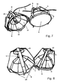
- Figures 7 and 8 show three-dimensional views of two UV lamp assemblies 1, wherein each having a lamp cap 2 and a concave reflector body 3.
- the right of the two UV lamp assemblies of Fig. 7 shows a filter disk 4 on the reflector body 3.
- Die on the other hand, the left-hand of the two UV lamp arrangements from FIG. 7 does not show a filter disk 4 am Reflector body 3, so that disposed within the cavity of the reflector body 3 UV burner 9 becomes visible.
- the holder of reflector body 3 via four gripping arms 8, which are formed from bent metal strips and a simple dismantling of reflector body 3 and filter disc 4 and thus allow replacement of the UV burner 9.
- the reflector body 3 is configured with facets 3f.
- FIG. 9 shows a UV lamp arrangement 1 in a three-dimensional view, in which the gripping arms 8 are formed so that they the base 2 at the reflector outlet opening with spring tension press against the reflector 3.
- FIG. 10 shows a lamp arrangement 1, in which a base 2 with two gripping arms 8 on the reflector body 3 is held.
- the gripping arms 8 are designed so that they the base. 2 clamp against the reflector neck 3a or configured as a ring member 3d.
- FIG. 11 shows a lamp arrangement 1, in three-dimensional representation, in which the gripper arms 8, similarly as in Fig. 9, are designed as Klammem, the base against the reflector. 3 Press, with the gripping arms 8 engage in the reflector opening.
- FIG. 12 shows a lamp arrangement 1, in which a base 2 with two gripping arms 8 on the reflector body 3 is held.
- the gripping arms 8 are formed as a U-profile bracket, the Base 2 against the reflector neck 3a or configured as a ring component 3d clamps.
Landscapes
- Engineering & Computer Science (AREA)
- General Engineering & Computer Science (AREA)
- Fastening Of Light Sources Or Lamp Holders (AREA)
- Non-Portable Lighting Devices Or Systems Thereof (AREA)
- Securing Globes, Refractors, Reflectors Or The Like (AREA)
Priority Applications (1)
| Application Number | Priority Date | Filing Date | Title |
|---|---|---|---|
| PL04021097T PL1515085T3 (pl) | 2003-09-15 | 2004-09-06 | Układ lampy UV i jego zastosowanie |
Applications Claiming Priority (4)
| Application Number | Priority Date | Filing Date | Title |
|---|---|---|---|
| DE2003142876 DE10342876B4 (de) | 2003-09-15 | 2003-09-15 | UV-Lampenanordnung und deren Verwendung |
| DE10342876 | 2003-09-15 | ||
| DE10346131 | 2003-10-01 | ||
| DE10346131A DE10346131A1 (de) | 2003-10-01 | 2003-10-01 | UV-Lampenanordnung und deren Verwendung |
Publications (3)
| Publication Number | Publication Date |
|---|---|
| EP1515085A2 true EP1515085A2 (fr) | 2005-03-16 |
| EP1515085A3 EP1515085A3 (fr) | 2013-07-24 |
| EP1515085B1 EP1515085B1 (fr) | 2015-06-24 |
Family
ID=34137328
Family Applications (1)
| Application Number | Title | Priority Date | Filing Date |
|---|---|---|---|
| EP04021097.3A Expired - Lifetime EP1515085B1 (fr) | 2003-09-15 | 2004-09-06 | Ensemble lampe UV et son utilisation |
Country Status (4)
| Country | Link |
|---|---|
| EP (1) | EP1515085B1 (fr) |
| ES (1) | ES2546011T3 (fr) |
| HU (1) | HUE025563T2 (fr) |
| PL (1) | PL1515085T3 (fr) |
Cited By (2)
| Publication number | Priority date | Publication date | Assignee | Title |
|---|---|---|---|---|
| EP1793159A1 (fr) * | 2005-12-05 | 2007-06-06 | Park, Shi-heung | Lampe à infrarouge |
| CN104456445A (zh) * | 2013-09-13 | 2015-03-25 | 海洋王(东莞)照明科技有限公司 | 灯具连接装置及照明灯具 |
Family Cites Families (5)
| Publication number | Priority date | Publication date | Assignee | Title |
|---|---|---|---|---|
| DE445204C (de) * | 1927-06-01 | Hedwig Koertge Geb Stutzer | Befestigungsvorrichtung fuer Reflektoren | |
| GB1475663A (en) * | 1975-10-24 | 1977-06-01 | Practical Prod Mfg Ltd | Reflector and bulbholder assembly |
| FR2638815B1 (fr) * | 1988-11-04 | 1992-08-28 | Megalit | Appareil d'eclairage a reflecteur porte-lampe amovible |
| DE9001445U1 (de) * | 1990-02-08 | 1990-04-12 | Hoffmeister-Leuchten GmbH & Co KG, 5880 Lüdenscheid | Elektrische Strahlerleuchte |
| DE10151850A1 (de) * | 2001-10-24 | 2003-05-15 | Heraeus Noblelight Gmbh | Bräunungsmodul mit einem Gehäuse |
-
2004
- 2004-09-06 ES ES04021097.3T patent/ES2546011T3/es not_active Expired - Lifetime
- 2004-09-06 EP EP04021097.3A patent/EP1515085B1/fr not_active Expired - Lifetime
- 2004-09-06 HU HUE04021097A patent/HUE025563T2/en unknown
- 2004-09-06 PL PL04021097T patent/PL1515085T3/pl unknown
Cited By (3)
| Publication number | Priority date | Publication date | Assignee | Title |
|---|---|---|---|---|
| EP1793159A1 (fr) * | 2005-12-05 | 2007-06-06 | Park, Shi-heung | Lampe à infrarouge |
| CN104456445A (zh) * | 2013-09-13 | 2015-03-25 | 海洋王(东莞)照明科技有限公司 | 灯具连接装置及照明灯具 |
| CN104456445B (zh) * | 2013-09-13 | 2019-04-16 | 海洋王(东莞)照明科技有限公司 | 灯具连接装置及照明灯具 |
Also Published As
| Publication number | Publication date |
|---|---|
| PL1515085T3 (pl) | 2015-11-30 |
| EP1515085B1 (fr) | 2015-06-24 |
| EP1515085A3 (fr) | 2013-07-24 |
| ES2546011T3 (es) | 2015-09-17 |
| HUE025563T2 (en) | 2016-03-29 |
Similar Documents
| Publication | Publication Date | Title |
|---|---|---|
| DE69624913T2 (de) | Elektrische reflektorlampe | |
| DE69203882T2 (de) | Lampen/Reflektor-Gefüge und elektrische Lampe zur Verwendung im Gefüge. | |
| DE102008052869B4 (de) | Leuchte mit LED-Tragschiene | |
| DE3033688C2 (fr) | ||
| DE3827528A1 (de) | Vorrichtung fuer die beleuchtung der backmuffel und des garraums | |
| DE69624090T2 (de) | Gesockelte elektrische lampe und leuchtvorrichtung mit einem reflektor und dazugehörige gesockelte elektrische lampe | |
| DE8803881U1 (de) | Kompakte Reflektorlampe | |
| EP1515085B1 (fr) | Ensemble lampe UV et son utilisation | |
| DE10342876B4 (de) | UV-Lampenanordnung und deren Verwendung | |
| EP0121819B1 (fr) | Lampe de réflecteur | |
| DE19855265A1 (de) | Elektrische Lampe und Beleuchtungsvorrichtung mit einer derartigen elektrischen Lampe | |
| DE2926531C2 (de) | Scheinwerfer mit einem aus Kunststoff bestehenden Reflektor | |
| EP2020678A2 (fr) | Lampe électrique dotée d'un piston extérieur et d'une lampe intégrée agencée dans le piston extérieur | |
| EP1009012B1 (fr) | Lampe électrique | |
| EP1435636A2 (fr) | Unité d'éclairage | |
| DE10122878B4 (de) | Beleuchtungseinrichtung für Backöfen | |
| EP0611916B1 (fr) | Lampe pour fours à micro-ondes | |
| DE19509112A1 (de) | Kompaktleuchtstofflampe mit kreisrundem Gasentladungsgefäß | |
| DE29622029U1 (de) | Elektrische Lampe | |
| EP1662248B1 (fr) | Support de source de rayonnement pour un appareil de résistance aux intempéries | |
| DE102004060918A1 (de) | PAR-Lampenanordnung | |
| EP1329931B1 (fr) | Lampe compacte à décharge à basse pression | |
| DE102013104150B4 (de) | Leuchtmittelhalterung und Verfahren zu deren Montage | |
| EP1045198A2 (fr) | Douille pour une lampe halogène | |
| DE112006003190T5 (de) | Glühlichtquelle mit selbstabdichtendem Befestigungssockel |
Legal Events
| Date | Code | Title | Description |
|---|---|---|---|
| PUAI | Public reference made under article 153(3) epc to a published international application that has entered the european phase |
Free format text: ORIGINAL CODE: 0009012 |
|
| 17P | Request for examination filed |
Effective date: 20040909 |
|
| AK | Designated contracting states |
Kind code of ref document: A2 Designated state(s): AT BE BG CH CY CZ DE DK EE ES FI FR GB GR HU IE IT LI LU MC NL PL PT RO SE SI SK TR |
|
| AX | Request for extension of the european patent |
Extension state: AL HR LT LV MK |
|
| PUAL | Search report despatched |
Free format text: ORIGINAL CODE: 0009013 |
|
| AK | Designated contracting states |
Kind code of ref document: A3 Designated state(s): AT BE BG CH CY CZ DE DK EE ES FI FR GB GR HU IE IT LI LU MC NL PL PT RO SE SI SK TR |
|
| AX | Request for extension of the european patent |
Extension state: AL HR LT LV MK |
|
| RIC1 | Information provided on ipc code assigned before grant |
Ipc: A61N 5/06 20060101ALI20130619BHEP Ipc: F21V 17/10 20060101AFI20130619BHEP |
|
| AKX | Designation fees paid |
Designated state(s): AT BE BG CH CY CZ DE DK EE ES FI FR GB GR HU IE IT LI LU MC NL PL PT RO SE SI SK TR |
|
| 17Q | First examination report despatched |
Effective date: 20140613 |
|
| GRAP | Despatch of communication of intention to grant a patent |
Free format text: ORIGINAL CODE: EPIDOSNIGR1 |
|
| RIC1 | Information provided on ipc code assigned before grant |
Ipc: A61N 5/06 20060101ALI20150304BHEP Ipc: F21V 17/14 20060101ALI20150304BHEP Ipc: F21V 19/00 20060101ALI20150304BHEP Ipc: F21V 17/10 20060101AFI20150304BHEP Ipc: F21V 27/02 20060101ALI20150304BHEP Ipc: F21V 17/06 20060101ALI20150304BHEP |
|
| INTG | Intention to grant announced |
Effective date: 20150324 |
|
| GRAS | Grant fee paid |
Free format text: ORIGINAL CODE: EPIDOSNIGR3 |
|
| GRAA | (expected) grant |
Free format text: ORIGINAL CODE: 0009210 |
|
| AK | Designated contracting states |
Kind code of ref document: B1 Designated state(s): AT BE BG CH CY CZ DE DK EE ES FI FR GB GR HU IE IT LI LU MC NL PL PT RO SE SI SK TR |
|
| REG | Reference to a national code |
Ref country code: GB Ref legal event code: FG4D Free format text: NOT ENGLISH |
|
| REG | Reference to a national code |
Ref country code: CH Ref legal event code: EP |
|
| REG | Reference to a national code |
Ref country code: AT Ref legal event code: REF Ref document number: 733072 Country of ref document: AT Kind code of ref document: T Effective date: 20150715 |
|
| REG | Reference to a national code |
Ref country code: IE Ref legal event code: FG4D Free format text: LANGUAGE OF EP DOCUMENT: GERMAN |
|
| REG | Reference to a national code |
Ref country code: DE Ref legal event code: R096 Ref document number: 502004014936 Country of ref document: DE |
|
| REG | Reference to a national code |
Ref country code: ES Ref legal event code: FG2A Ref document number: 2546011 Country of ref document: ES Kind code of ref document: T3 Effective date: 20150917 |
|
| REG | Reference to a national code |
Ref country code: NL Ref legal event code: FP |
|
| PG25 | Lapsed in a contracting state [announced via postgrant information from national office to epo] |
Ref country code: FI Free format text: LAPSE BECAUSE OF FAILURE TO SUBMIT A TRANSLATION OF THE DESCRIPTION OR TO PAY THE FEE WITHIN THE PRESCRIBED TIME-LIMIT Effective date: 20150624 |
|
| PG25 | Lapsed in a contracting state [announced via postgrant information from national office to epo] |
Ref country code: BG Free format text: LAPSE BECAUSE OF FAILURE TO SUBMIT A TRANSLATION OF THE DESCRIPTION OR TO PAY THE FEE WITHIN THE PRESCRIBED TIME-LIMIT Effective date: 20150924 Ref country code: GR Free format text: LAPSE BECAUSE OF FAILURE TO SUBMIT A TRANSLATION OF THE DESCRIPTION OR TO PAY THE FEE WITHIN THE PRESCRIBED TIME-LIMIT Effective date: 20150925 |
|
| REG | Reference to a national code |
Ref country code: PL Ref legal event code: T3 |
|
| PG25 | Lapsed in a contracting state [announced via postgrant information from national office to epo] |
Ref country code: EE Free format text: LAPSE BECAUSE OF FAILURE TO SUBMIT A TRANSLATION OF THE DESCRIPTION OR TO PAY THE FEE WITHIN THE PRESCRIBED TIME-LIMIT Effective date: 20150624 |
|
| PG25 | Lapsed in a contracting state [announced via postgrant information from national office to epo] |
Ref country code: PT Free format text: LAPSE BECAUSE OF FAILURE TO SUBMIT A TRANSLATION OF THE DESCRIPTION OR TO PAY THE FEE WITHIN THE PRESCRIBED TIME-LIMIT Effective date: 20151026 Ref country code: SK Free format text: LAPSE BECAUSE OF FAILURE TO SUBMIT A TRANSLATION OF THE DESCRIPTION OR TO PAY THE FEE WITHIN THE PRESCRIBED TIME-LIMIT Effective date: 20150624 Ref country code: RO Free format text: LAPSE BECAUSE OF NON-PAYMENT OF DUE FEES Effective date: 20150624 Ref country code: CZ Free format text: LAPSE BECAUSE OF FAILURE TO SUBMIT A TRANSLATION OF THE DESCRIPTION OR TO PAY THE FEE WITHIN THE PRESCRIBED TIME-LIMIT Effective date: 20150624 |
|
| REG | Reference to a national code |
Ref country code: HU Ref legal event code: AG4A Ref document number: E025563 Country of ref document: HU Ref country code: DE Ref legal event code: R097 Ref document number: 502004014936 Country of ref document: DE |
|
| PG25 | Lapsed in a contracting state [announced via postgrant information from national office to epo] |
Ref country code: MC Free format text: LAPSE BECAUSE OF FAILURE TO SUBMIT A TRANSLATION OF THE DESCRIPTION OR TO PAY THE FEE WITHIN THE PRESCRIBED TIME-LIMIT Effective date: 20150624 Ref country code: DK Free format text: LAPSE BECAUSE OF FAILURE TO SUBMIT A TRANSLATION OF THE DESCRIPTION OR TO PAY THE FEE WITHIN THE PRESCRIBED TIME-LIMIT Effective date: 20150624 Ref country code: LU Free format text: LAPSE BECAUSE OF FAILURE TO SUBMIT A TRANSLATION OF THE DESCRIPTION OR TO PAY THE FEE WITHIN THE PRESCRIBED TIME-LIMIT Effective date: 20150906 |
|
| PLBE | No opposition filed within time limit |
Free format text: ORIGINAL CODE: 0009261 |
|
| REG | Reference to a national code |
Ref country code: CH Ref legal event code: PL |
|
| STAA | Information on the status of an ep patent application or granted ep patent |
Free format text: STATUS: NO OPPOSITION FILED WITHIN TIME LIMIT |
|
| GBPC | Gb: european patent ceased through non-payment of renewal fee |
Effective date: 20150924 |
|
| 26N | No opposition filed |
Effective date: 20160329 |
|
| REG | Reference to a national code |
Ref country code: IE Ref legal event code: MM4A |
|
| REG | Reference to a national code |
Ref country code: FR Ref legal event code: ST Effective date: 20160531 |
|
| PG25 | Lapsed in a contracting state [announced via postgrant information from national office to epo] |
Ref country code: LI Free format text: LAPSE BECAUSE OF NON-PAYMENT OF DUE FEES Effective date: 20150930 Ref country code: IE Free format text: LAPSE BECAUSE OF NON-PAYMENT OF DUE FEES Effective date: 20150906 Ref country code: GB Free format text: LAPSE BECAUSE OF NON-PAYMENT OF DUE FEES Effective date: 20150924 Ref country code: CH Free format text: LAPSE BECAUSE OF NON-PAYMENT OF DUE FEES Effective date: 20150930 |
|
| PG25 | Lapsed in a contracting state [announced via postgrant information from national office to epo] |
Ref country code: SI Free format text: LAPSE BECAUSE OF FAILURE TO SUBMIT A TRANSLATION OF THE DESCRIPTION OR TO PAY THE FEE WITHIN THE PRESCRIBED TIME-LIMIT Effective date: 20150624 Ref country code: FR Free format text: LAPSE BECAUSE OF NON-PAYMENT OF DUE FEES Effective date: 20150930 |
|
| REG | Reference to a national code |
Ref country code: AT Ref legal event code: MM01 Ref document number: 733072 Country of ref document: AT Kind code of ref document: T Effective date: 20150906 |
|
| PG25 | Lapsed in a contracting state [announced via postgrant information from national office to epo] |
Ref country code: AT Free format text: LAPSE BECAUSE OF NON-PAYMENT OF DUE FEES Effective date: 20150906 |
|
| PG25 | Lapsed in a contracting state [announced via postgrant information from national office to epo] |
Ref country code: SE Free format text: LAPSE BECAUSE OF FAILURE TO SUBMIT A TRANSLATION OF THE DESCRIPTION OR TO PAY THE FEE WITHIN THE PRESCRIBED TIME-LIMIT Effective date: 20150624 Ref country code: CY Free format text: LAPSE BECAUSE OF FAILURE TO SUBMIT A TRANSLATION OF THE DESCRIPTION OR TO PAY THE FEE WITHIN THE PRESCRIBED TIME-LIMIT Effective date: 20150624 |
|
| PG25 | Lapsed in a contracting state [announced via postgrant information from national office to epo] |
Ref country code: TR Free format text: LAPSE BECAUSE OF FAILURE TO SUBMIT A TRANSLATION OF THE DESCRIPTION OR TO PAY THE FEE WITHIN THE PRESCRIBED TIME-LIMIT Effective date: 20150624 |
|
| REG | Reference to a national code |
Ref country code: DE Ref legal event code: R082 Ref document number: 502004014936 Country of ref document: DE Representative=s name: BRAND, NORMEN, DR. RER. NAT., DE Ref country code: DE Ref legal event code: R082 Ref document number: 502004014936 Country of ref document: DE Representative=s name: EULER, MATTHIAS, DR., DE Ref country code: DE Ref legal event code: R082 Ref document number: 502004014936 Country of ref document: DE Representative=s name: BRAND, NORMEN, DIPL.-CHEM. UNIV. DR. RER. NAT., DE |
|
| REG | Reference to a national code |
Ref country code: DE Ref legal event code: R082 Ref document number: 502004014936 Country of ref document: DE Representative=s name: BRAND, NORMEN, DR. RER. NAT., DE Ref country code: DE Ref legal event code: R082 Ref document number: 502004014936 Country of ref document: DE Representative=s name: BRAND, NORMEN, DIPL.-CHEM. UNIV. DR. RER. NAT., DE |
|
| PGFP | Annual fee paid to national office [announced via postgrant information from national office to epo] |
Ref country code: DE Payment date: 20200925 Year of fee payment: 17 Ref country code: NL Payment date: 20200925 Year of fee payment: 17 |
|
| PGFP | Annual fee paid to national office [announced via postgrant information from national office to epo] |
Ref country code: IT Payment date: 20200922 Year of fee payment: 17 Ref country code: PL Payment date: 20200828 Year of fee payment: 17 Ref country code: BE Payment date: 20200925 Year of fee payment: 17 |
|
| PGFP | Annual fee paid to national office [announced via postgrant information from national office to epo] |
Ref country code: ES Payment date: 20201120 Year of fee payment: 17 Ref country code: HU Payment date: 20201021 Year of fee payment: 17 |
|
| REG | Reference to a national code |
Ref country code: DE Ref legal event code: R119 Ref document number: 502004014936 Country of ref document: DE |
|
| REG | Reference to a national code |
Ref country code: NL Ref legal event code: MM Effective date: 20211001 |
|
| REG | Reference to a national code |
Ref country code: BE Ref legal event code: MM Effective date: 20210930 |
|
| PG25 | Lapsed in a contracting state [announced via postgrant information from national office to epo] |
Ref country code: NL Free format text: LAPSE BECAUSE OF NON-PAYMENT OF DUE FEES Effective date: 20211001 |
|
| PG25 | Lapsed in a contracting state [announced via postgrant information from national office to epo] |
Ref country code: HU Free format text: LAPSE BECAUSE OF NON-PAYMENT OF DUE FEES Effective date: 20210907 Ref country code: DE Free format text: LAPSE BECAUSE OF NON-PAYMENT OF DUE FEES Effective date: 20220401 Ref country code: BE Free format text: LAPSE BECAUSE OF NON-PAYMENT OF DUE FEES Effective date: 20210930 |
|
| REG | Reference to a national code |
Ref country code: ES Ref legal event code: FD2A Effective date: 20221026 |
|
| PG25 | Lapsed in a contracting state [announced via postgrant information from national office to epo] |
Ref country code: IT Free format text: LAPSE BECAUSE OF NON-PAYMENT OF DUE FEES Effective date: 20210906 |
|
| PG25 | Lapsed in a contracting state [announced via postgrant information from national office to epo] |
Ref country code: ES Free format text: LAPSE BECAUSE OF NON-PAYMENT OF DUE FEES Effective date: 20210907 |
|
| PG25 | Lapsed in a contracting state [announced via postgrant information from national office to epo] |
Ref country code: PL Free format text: LAPSE BECAUSE OF NON-PAYMENT OF DUE FEES Effective date: 20210906 |