EP1515058B1 - Kupplungsausrücksystem eines Fahrzeuges - Google Patents
Kupplungsausrücksystem eines Fahrzeuges Download PDFInfo
- Publication number
- EP1515058B1 EP1515058B1 EP04300576A EP04300576A EP1515058B1 EP 1515058 B1 EP1515058 B1 EP 1515058B1 EP 04300576 A EP04300576 A EP 04300576A EP 04300576 A EP04300576 A EP 04300576A EP 1515058 B1 EP1515058 B1 EP 1515058B1
- Authority
- EP
- European Patent Office
- Prior art keywords
- support
- shoe
- relief
- clutch
- assembly
- Prior art date
- Legal status (The legal status is an assumption and is not a legal conclusion. Google has not performed a legal analysis and makes no representation as to the accuracy of the status listed.)
- Expired - Lifetime
Links
Images
Classifications
-
- F—MECHANICAL ENGINEERING; LIGHTING; HEATING; WEAPONS; BLASTING
- F16—ENGINEERING ELEMENTS AND UNITS; GENERAL MEASURES FOR PRODUCING AND MAINTAINING EFFECTIVE FUNCTIONING OF MACHINES OR INSTALLATIONS; THERMAL INSULATION IN GENERAL
- F16D—COUPLINGS FOR TRANSMITTING ROTATION; CLUTCHES; BRAKES
- F16D23/00—Details of mechanically-actuated clutches not specific for one distinct type
- F16D23/12—Mechanical clutch-actuating mechanisms arranged outside the clutch as such
- F16D23/14—Clutch-actuating sleeves or bearings; Actuating members directly connected to clutch-actuating sleeves or bearings
- F16D2023/141—Clutch-actuating sleeves or bearings; Actuating members directly connected to clutch-actuating sleeves or bearings characterised by using a fork; Details of forks
Definitions
- the present invention relates to an assembly intended to be put in place on the fork of a disengaging system of a motor vehicle, and such a system, in particular for a manual gearbox.
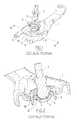
- a motor vehicle disengaging system comprises a release fork 1, a ball-and-socket axis 2 comprising a bit 3 having a spherical segment surface and a support 4 forming a housing in which engages the tip 3, so as to define a ball-type connection 8 between the fork 1 and the ball axis 2.
- the end piece 3 is applied to a spherical cap-shaped pad 5 disposed in a recess 6 of the fork 1, this pad 5 forming a sliding surface for the end piece 3.
- This clutch system operates as follows.
- the release fork 1 When a user of the motor vehicle presses the clutch pedal, the release fork 1, either via a cable connected to the clutch pedal, or via a hydraulic mechanism such as a cylinder actuated by a distributor connected to the clutch pedal, tilts around the ball joint 8. This tilting moves nibs 9 of the release fork 1, which causes disengagement of disengagement disks.
- the fork 1 can be made of steel, for example pressed sheet metal or forged steel.
- the ball shaft 2 fixed to the gearbox housing, for example by screwing, can be made of steel.
- the pad 5 may be made of a flexible material such as a material containing PTFE and a metal grid, or rigid such as a material containing PTFE and a metal plate.
- the pad 5 is stuck on the tip 3.
- the various parts constituting the clutch release system are generally delivered without being assembled.
- the application FR 2 722 262 describes a clutch control device in which the fork is equipped, before it is placed on a ball joint, with a ball body fixed to the fork by crimping or by means of rivets.
- the present invention aims to provide a motor vehicle disengaging system for easy assembly.
- the invention thus relates to an assembly intended to be put in place on the fork of a motor vehicle disengaging system according to claim 1.
- the invention it is possible to assemble the pad with the support on a first production site and deliver the support with the assembled pad to a second place where the disengagement system is assembled entirely. This simplifies the assembly of the clutch system.
- the assembly of the pad on the support can also be performed in an automated manner, in particular on a machine designed for this purpose.
- the retaining means provided on the support are arranged so as to provide a clearance between the pad and the support allowing relative movement of the pad relative to the support.
- the invention thus ensures automatic centering of the pad with respect to the declutching fork and relative to the ball axis, during assembly of the complete disengagement system.
- the fixing relief or reliefs may each be formed by an elastically deformable tab.
- the relief or reliefs may each be formed by a pin capable of being flattened, in particular by pegging.
- the fixing relief may be formed by an annular lip adapted to be deformed, in particular by pegging.
- the portion of the pad resting on the bearing or bearings is preferably a peripheral portion of the pad, which may comprise a substantially flat annular peripheral portion.
- the support has a cylindrical inner wall, and the bearing or surfaces are formed on one or more shapes projecting from the inner wall.
- the support can be made in one piece of thermoplastic material, in particular by injection molding.
- the pad may be made of a material chosen from: a material containing PTFE and a metal grid, a thermoplastic material, in particular a filled polyamide, a polyimide, POM, PPS or PEEK, this list not being limiting.
- the declutching fork comprises one or more orifices and the support comprises one or more tabs, in particular elastically deformable, capable of engaging in the orifices of the fork, allowing the fixing the support on the fork.
- the support may comprise one or more attachment reliefs capable of being deformed, in particular by pegging, to allow the support of the pad on the support.
- the deformation of the fixing relief can be carried out at ambient temperature.
- the support prior to the deformation of the fixing relief, the support can be heated.
- the deformation of the fixing relief can be performed using a preheated tool or a tool on which ultrasound is generated.
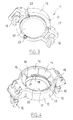
- FIG. 3 shows an assembly 11 according to the invention intended to equip a motor vehicle disengaging system similar to that described with reference to FIGS. 1 and 2.
- This assembly 11 comprises a support 12 comprising a ring 13 provided with a cylindrical inner wall 14, as can be seen in FIG. 4.
- the support 12 is made by injection molding of a thermoplastic material.
- the ring 13 defines a housing 17 for the tip 3 of the ball pin 2 and is provided with a plurality of tongues 15 forming stops to retain the tip 3 in the housing 17.
- the support 12 comprises, on either side of the ring 13, two fastening tabs 16 adapted to engage in the orifices 19 of the release fork 1.
- the support 12 further comprises teeth 18 projecting from the cylindrical inner wall 14 and forming bearing surfaces on which a substantially flat annular peripheral portion 21 of a shoe 20 is applied.
- This pad 20 has a generally spherical cap shape and may be made of a flexible material, in particular containing PTFE and a metal grid or, alternatively, a thermoplastic material having satisfactory tribological properties, in particular a filled polyamide, POM, PPS or PEEK.
- the pad 20 is positioned on the bearing surfaces 18 and held on it with the aid of a plurality of fixing reliefs 23 made in one piece with the support 12.
- These fixing reliefs 23, in the example in question, are each formed by an elastically deformable tab so that the pad 20 can be placed on the support 12 by snapping.
- the pad 20 may, in a variant, be put in place on the support 12 by first discarding the elastically deformable tabs 23 with the aid of a suitable tool, then placing the pad 20 on the bearing surfaces 18 before allowing the springback legs 23.
- the assembly 11 consisting of the support 12 and the pad 20 can be delivered in the assembled state.
- the pad 20 is fixed on the support 12 with a clearance allowing the pad 20 to be automatically centered during assembly of the complete clutch system.
- the pad 20 can be fixed on the support 12 in a different manner.
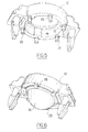
- the support 12 comprises a plurality of pins 25 able to be flattened, in particular by pegging, which pins make it possible, after placing the shoe 20 on the bearing surfaces 18 and deformation of the pins. 25, to retain this pad 20.
- the pins 25 have a substantially cylindrical shape over their entire height.
- the pins may have a different shape, for example nail head, round or oblong, or be constituted by a folded tab.
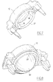
- FIGS. 7 and 8 show a support 12 comprising a fixing relief consisting of an annular lip 27 which can be deformed, in particular by pegging, and making it possible, in the deformed state, to retain the pad 20 on the bearing surfaces 18 .
- annular lip 27 is uninterrupted.
- it can be interrupted in one or more locations.
- the deformation of the fixing reliefs can be carried out in different ways.
- the deformation of the fixing relief can for example be carried out at ambient temperature.
- the support prior to the deformation of the fixing relief, the support can be heated.
- the deformation of the fixing relief can be effected by means of a preheated tool or by means of a tool on which ultrasound is generated.
Landscapes
- Engineering & Computer Science (AREA)
- General Engineering & Computer Science (AREA)
- Mechanical Engineering (AREA)
- Mechanical Operated Clutches (AREA)
- Pivots And Pivotal Connections (AREA)
- Arrangement And Mounting Of Devices That Control Transmission Of Motive Force (AREA)
- Connection Of Motors, Electrical Generators, Mechanical Devices, And The Like (AREA)
- Footwear And Its Accessory, Manufacturing Method And Apparatuses (AREA)
- Clamps And Clips (AREA)
Claims (18)
- Einheit (11), die dazu bestimmt ist, auf der Gabel eines Kupplungssystems eines Kraftfahrzeugs angeordnet zu werden, wobei die Einheit umfasst:- ein Gleitstück (20), das eine Gleitfläche für einen Ansatz (3) einer Drehgelenksachse (2) des Kupplungssystems bildet,- eine Stütze (12), die eine Lagerung (17) umfasst, um den Ansatz (3) der Drehgelenksachse (2) aufzunehmen,dadurch gekennzeichnet, dass die Stütze (12) Haltemittel (18; 23; 25, 27) umfasst, um die Befestigung des Gleitstücks (20) auf dem Träger (12) zu ermöglichen, wobei die Haltemittel eine oder mehrere Flächen (18), an die mindestens ein Abschnitt des Gleitstücks angelegt wird, und einen oder mehrere Befestigungsvorsprünge (23; 25; 27) umfassen, die derart angeordnet sind, dass sie das Gleitstück an der oder den Flächen (18) angelegt halten.
- Einheit nach Anspruch 1, dadurch gekennzeichnet, dass die auf der Stütze (12) vorgesehenen Haltemittel derart angeordnet sind, dass sie ein Spiel zwischen dem Gleitstück und der Stütze frei lassen, das eine relative Verschiebung des Gleitstücks (20) in Bezug auf die Stütze (12) ermöglicht.
- Einheit nach Anspruch 1 oder 2, dadurch gekennzeichnet, dass der oder die Befestigungsvorsprünge jeweils von einem elastisch verformbaren Befestigungseisen (23) gebildet sind.
- Einheit nach Anspruch 1 oder 2, dadurch gekennzeichnet, dass der oder die Befestigungsvorsprünge jeweils von einem Keil (25) gebildet sind, der insbesondere durch Schellen abgeflacht werden kann.
- Einheit nach Anspruch 1 oder 2, dadurch gekennzeichnet, dass der Befestigungsvorsprung von einer Ringlippe (27) gebildet ist, die insbesondere durch Schellen verformt werden kann.
- Einheit nach einem der vorgenannten Ansprüche, dadurch gekennzeichnet, dass der Abschnitt des Gleitstücks, der auf der oder den Flächen aufliegt, ein Umfangsabschnitt (21) des Gleitstücks (20) ist.
- Einheit nach einem der vorhergehenden Ansprüche, dadurch gekennzeichnet, dass das Gleitstück (20) einen im Wesentlichen flachen ringförmigen Umfangsabschnitt (21) umfasst.
- Einheit nach einem der vorhergehenden Ansprüche, wobei die Stütze eine zylindrische Innenwand (14) umfasst, dadurch gekennzeichnet, dass die Fläche(n) (18) auf einer oder mehreren vorspringenden Formen der Innenwand (14) ausgebildet sind.
- Einheit nach einem der vorhergehenden Ansprüche, dadurch gekennzeichnet, dass die Stütze (12) aus einem Stück aus Thermoplast insbesondere durch Spritzguss hergestellt ist.
- Einheit nach einem der vorhergehenden Ansprüche, dadurch gekennzeichnet, dass das Gleitstück (20) aus einem Material hergestellt ist, das ausgewählt wird unter: einem Material, das PTFE und ein Metallgitter enthält, einem Thermoplast, insbesondere einem Polyamid mit Füllstoffen, einem Polyimid, POM, PPS oder PEEK.
- Kupplungssystem eines Kraftfahrzeugs, umfassend:- eine Kupplungsgabel (1),- eine Drehgelenksachse (2) mit einem Ansatz (3),- eine Einheit (11), wie in einem der Ansprüche 1 bis 10 definiert, die auf der Kupplungsgabel (1) befestigt ist.
- Kupplungssystem nach Anspruch 11, dadurch gekennzeichnet, dass die Kupplungsgabel (1) eine oder mehrere Öffnungen umfasst, und dadurch, dass die Stütze ein oder mehrere Befestigungseisen (16) umfasst, die insbesondere elastisch verformbar und in der Lage sind, in die Öffnung(en) (19) der Gabel einzugreifen, wodurch die Befestigung der Stütze auf der Gabel möglich ist.
- Verfahren zur Herstellung einer Einheit (11), wie in einem der Ansprüche 1 bis 10 definiert, die dazu bestimmt ist, in ein Kupplungssystem eines Kraftfahrzeugs eingebaut zu werden, dadurch gekennzeichnet, dass es die folgenden Schritte umfasst:- Bereitstellung eines Gleitstücks (20), das eine Gleitfläche für einen Ansatz (3) einer Drehgelenksachse (2) eines Kupplungssystems bildet,- Bereitstellung einer Stütze (12), umfassend eine Lagerung (17), um den Ansatz (3) der Drehgelenksachse (2) aufzunehmen, und derart angeordnet, dass sie die Befestigung des Gleitstücks auf der Stütze ermöglicht,- Befestigung des Gleitstücks auf der Stütze mit Hilfe von Haltemitteln der Stütze.
- Verfahren nach Anspruch 13, dadurch gekennzeichnet, dass die Stütze (12) einen oder mehrere Befestigungsvorsprünge (25; 27) umfasst, die insbesondere durch Schellen verformt werden, um das Halten des Gleitstücks auf der Stütze zu ermöglichen.
- Verfahren nach Anspruch 14, dadurch gekennzeichnet, dass die Verformung des Befestigungsvorsprungs bei Raumtemperatur erfolgt.
- Verfahren nach Anspruch 14, dadurch gekennzeichnet, dass vor der Verformung des Befestigungsvorsprungs die Stütze erhitzt wird.
- Verfahren nach Anspruch 14, dadurch gekennzeichnet, dass die Verformung des Befestigungsvorsprungs mit Hilfe eines vorerhitzten Werkzeugs erfolgt.
- Verfahren nach Anspruch 14, dadurch gekennzeichnet, dass die Verformung des Befestigungsvorsprungs mit Hilfe eines Werkzeugs erfolgt, auf dem Ultraschall erzeugt wird.
Applications Claiming Priority (2)
| Application Number | Priority Date | Filing Date | Title |
|---|---|---|---|
| FR0310696A FR2859772B1 (fr) | 2003-09-11 | 2003-09-11 | Ensemble pour systeme de debrayage de vehicule automobile |
| FR0310696 | 2003-09-11 |
Publications (2)
| Publication Number | Publication Date |
|---|---|
| EP1515058A1 EP1515058A1 (de) | 2005-03-16 |
| EP1515058B1 true EP1515058B1 (de) | 2006-07-26 |
Family
ID=34130793
Family Applications (1)
| Application Number | Title | Priority Date | Filing Date |
|---|---|---|---|
| EP04300576A Expired - Lifetime EP1515058B1 (de) | 2003-09-11 | 2004-09-07 | Kupplungsausrücksystem eines Fahrzeuges |
Country Status (7)
| Country | Link |
|---|---|
| US (1) | US20050056517A1 (de) |
| EP (1) | EP1515058B1 (de) |
| AT (1) | ATE334320T1 (de) |
| BR (1) | BRPI0403785A (de) |
| DE (1) | DE602004001645T2 (de) |
| FR (1) | FR2859772B1 (de) |
| MX (1) | MXPA04008825A (de) |
Families Citing this family (1)
| Publication number | Priority date | Publication date | Assignee | Title |
|---|---|---|---|---|
| JP2015001268A (ja) * | 2013-06-14 | 2015-01-05 | トヨタ自動車株式会社 | クラッチ装置 |
Family Cites Families (7)
| Publication number | Priority date | Publication date | Assignee | Title |
|---|---|---|---|---|
| DE3612419A1 (de) * | 1986-04-12 | 1987-10-22 | Schaeffler Waelzlager Kg | Lagerung eines kupplungshebels an kraftfahrzeugen |
| JPH01172610A (ja) * | 1987-12-25 | 1989-07-07 | Ishikawa Tekko Kk | ポールジョイント及びその製造方法 |
| DE3801460C1 (en) * | 1988-01-20 | 1989-08-24 | Adam Opel Ag, 6090 Ruesselsheim, De | Motor-vehicle friction clutch that can be operated by means of a release lever |
| FR2641831B1 (fr) * | 1989-01-19 | 1991-04-26 | Peugeot | Articulation a rotule |
| FR2722262B1 (fr) * | 1994-07-07 | 1996-08-23 | Renault | Dispositif de commande d'embrayage |
| DE4433762C2 (de) * | 1994-09-22 | 1998-09-24 | Trw Fahrwerksyst Gmbh & Co | Kugelgelenk |
| US6123181A (en) * | 1998-07-28 | 2000-09-26 | Mannesmann Sachs Ag | Articulation head for a clutch-release rocker arm of a friction clutch |
-
2003
- 2003-09-11 FR FR0310696A patent/FR2859772B1/fr not_active Expired - Fee Related
-
2004
- 2004-09-07 AT AT04300576T patent/ATE334320T1/de not_active IP Right Cessation
- 2004-09-07 EP EP04300576A patent/EP1515058B1/de not_active Expired - Lifetime
- 2004-09-07 DE DE602004001645T patent/DE602004001645T2/de not_active Expired - Lifetime
- 2004-09-09 BR BR0403785-5A patent/BRPI0403785A/pt not_active IP Right Cessation
- 2004-09-09 US US10/937,743 patent/US20050056517A1/en not_active Abandoned
- 2004-09-10 MX MXPA04008825A patent/MXPA04008825A/es unknown
Also Published As
| Publication number | Publication date |
|---|---|
| US20050056517A1 (en) | 2005-03-17 |
| MXPA04008825A (es) | 2005-04-19 |
| EP1515058A1 (de) | 2005-03-16 |
| ATE334320T1 (de) | 2006-08-15 |
| FR2859772B1 (fr) | 2005-11-11 |
| DE602004001645D1 (de) | 2006-09-07 |
| FR2859772A1 (fr) | 2005-03-18 |
| BRPI0403785A (pt) | 2005-05-24 |
| DE602004001645T2 (de) | 2007-08-09 |
Similar Documents
| Publication | Publication Date | Title |
|---|---|---|
| FR2817596A1 (fr) | Systeme d'assemblage au moyen d'un dispositif d'ancrage a billes | |
| FR2565644A1 (fr) | Fixation d'un roulement dans un logement ou analogue | |
| FR2544429A1 (fr) | Procede pour le montage d'une butee de debrayage, et butee de debrayage correspondante, notamment pour vehicule automobile | |
| FR2961280A1 (fr) | Dispositif de butee de debrayage comprenant une bague d'usure. | |
| EP1612443A1 (de) | Kupplungsausrücklager und Verfahren zu seiner Herstellung. | |
| US5934151A (en) | Vehicle push rod and pedal assembly | |
| FR2745616A1 (fr) | Dispositif de maintien, notamment pour vehicule automobile | |
| FR2777328A1 (fr) | Dispositif de manoeuvre pour un embrayage | |
| FR2626053A1 (fr) | Embrayage de verrouillage pour appareil d'accouplement hydrocinetique, notamment pour vehicule automobile | |
| EP1515058B1 (de) | Kupplungsausrücksystem eines Fahrzeuges | |
| FR2688560A1 (fr) | Butee d'embrayage a commande hydraulique. | |
| FR3026801A1 (fr) | Amortisseur, notamment pour un embrayage d'un vehicule automobile | |
| EP0845615B1 (de) | Kupplungsausrüstvorrichtung | |
| EP3234396B1 (de) | Kupplungsvorrichtung für ein kraftfahrzeug | |
| EP3559483B1 (de) | Abstandsvorrichtung mit winkelanpassung | |
| EP1058793B1 (de) | Hydraulischer kupplngsgeberzylinder mit verbesserter, axialer befestigung der kolbenstange am kolben | |
| EP2083206B1 (de) | Anschlussvorrichtung für den Transfer eines Fluids, Kreislauf, der diese Vorrichtung umfasst, und entsprechendes Montage-/Demontageverfahren | |
| EP3346306B1 (de) | Lösbare anschlussvorrichtung für einen lichtwellenleiter, und anwendung in einem kraftfahrzeug, optisches übertragungsmodul, das mit einer solchen vorrichtung ausgestattet ist | |
| EP2898228B1 (de) | Einsatz zur unterstützung eines kraftfahrzeugs, anordnung mit diesem einsatz und kraftfahrzeug mit dieser anordnung | |
| EP0836685B1 (de) | Befestigung eines kupplungsrücklagers | |
| FR2722262A1 (fr) | Dispositif de commande d'embrayage | |
| FR2979399A1 (fr) | Dispositif de fixation adapte a etre fixe a une tige | |
| FR2669980A1 (fr) | Butee de debrayage a rondelle elastique externe, notamment pour vehicules automobiles. | |
| EP0421851B1 (de) | Zugkraftbetätigtes Kupplungslager | |
| FR2879523A1 (fr) | Levier de commande de boite de vitesses de vehicule automobile, procede de montage et procede de demontage d'un tel levier |
Legal Events
| Date | Code | Title | Description |
|---|---|---|---|
| PUAI | Public reference made under article 153(3) epc to a published international application that has entered the european phase |
Free format text: ORIGINAL CODE: 0009012 |
|
| AK | Designated contracting states |
Kind code of ref document: A1 Designated state(s): AT BE BG CH CY CZ DE DK EE ES FI FR GB GR HU IE IT LI LU MC NL PL PT RO SE SI SK TR |
|
| AX | Request for extension of the european patent |
Extension state: AL HR LT LV MK |
|
| 17P | Request for examination filed |
Effective date: 20050604 |
|
| AKX | Designation fees paid |
Designated state(s): AT BE BG CH CY CZ DE DK EE ES FI FR GB GR HU IE IT LI LU MC NL PL PT RO SE SI SK TR |
|
| GRAP | Despatch of communication of intention to grant a patent |
Free format text: ORIGINAL CODE: EPIDOSNIGR1 |
|
| GRAS | Grant fee paid |
Free format text: ORIGINAL CODE: EPIDOSNIGR3 |
|
| GRAA | (expected) grant |
Free format text: ORIGINAL CODE: 0009210 |
|
| AK | Designated contracting states |
Kind code of ref document: B1 Designated state(s): AT BE BG CH CY CZ DE DK EE ES FI FR GB GR HU IE IT LI LU MC NL PL PT RO SE SI SK TR |
|
| PG25 | Lapsed in a contracting state [announced via postgrant information from national office to epo] |
Ref country code: FI Free format text: LAPSE BECAUSE OF FAILURE TO SUBMIT A TRANSLATION OF THE DESCRIPTION OR TO PAY THE FEE WITHIN THE PRESCRIBED TIME-LIMIT Effective date: 20060726 Ref country code: IT Free format text: LAPSE BECAUSE OF FAILURE TO SUBMIT A TRANSLATION OF THE DESCRIPTION OR TO PAY THE FEE WITHIN THE PRESCRIBED TIME-LIMIT;WARNING: LAPSES OF ITALIAN PATENTS WITH EFFECTIVE DATE BEFORE 2007 MAY HAVE OCCURRED AT ANY TIME BEFORE 2007. THE CORRECT EFFECTIVE DATE MAY BE DIFFERENT FROM THE ONE RECORDED. Effective date: 20060726 Ref country code: CZ Free format text: LAPSE BECAUSE OF FAILURE TO SUBMIT A TRANSLATION OF THE DESCRIPTION OR TO PAY THE FEE WITHIN THE PRESCRIBED TIME-LIMIT Effective date: 20060726 Ref country code: GB Free format text: LAPSE BECAUSE OF FAILURE TO SUBMIT A TRANSLATION OF THE DESCRIPTION OR TO PAY THE FEE WITHIN THE PRESCRIBED TIME-LIMIT Effective date: 20060726 Ref country code: SI Free format text: LAPSE BECAUSE OF FAILURE TO SUBMIT A TRANSLATION OF THE DESCRIPTION OR TO PAY THE FEE WITHIN THE PRESCRIBED TIME-LIMIT Effective date: 20060726 Ref country code: AT Free format text: LAPSE BECAUSE OF FAILURE TO SUBMIT A TRANSLATION OF THE DESCRIPTION OR TO PAY THE FEE WITHIN THE PRESCRIBED TIME-LIMIT Effective date: 20060726 Ref country code: SK Free format text: LAPSE BECAUSE OF FAILURE TO SUBMIT A TRANSLATION OF THE DESCRIPTION OR TO PAY THE FEE WITHIN THE PRESCRIBED TIME-LIMIT Effective date: 20060726 Ref country code: RO Free format text: LAPSE BECAUSE OF FAILURE TO SUBMIT A TRANSLATION OF THE DESCRIPTION OR TO PAY THE FEE WITHIN THE PRESCRIBED TIME-LIMIT Effective date: 20060726 Ref country code: IE Free format text: LAPSE BECAUSE OF FAILURE TO SUBMIT A TRANSLATION OF THE DESCRIPTION OR TO PAY THE FEE WITHIN THE PRESCRIBED TIME-LIMIT Effective date: 20060726 Ref country code: PL Free format text: LAPSE BECAUSE OF FAILURE TO SUBMIT A TRANSLATION OF THE DESCRIPTION OR TO PAY THE FEE WITHIN THE PRESCRIBED TIME-LIMIT Effective date: 20060726 Ref country code: NL Free format text: LAPSE BECAUSE OF FAILURE TO SUBMIT A TRANSLATION OF THE DESCRIPTION OR TO PAY THE FEE WITHIN THE PRESCRIBED TIME-LIMIT Effective date: 20060726 |
|
| REG | Reference to a national code |
Ref country code: GB Ref legal event code: FG4D Free format text: NOT ENGLISH |
|
| REG | Reference to a national code |
Ref country code: CH Ref legal event code: EP |
|
| REG | Reference to a national code |
Ref country code: IE Ref legal event code: FG4D Free format text: LANGUAGE OF EP DOCUMENT: FRENCH |
|
| REF | Corresponds to: |
Ref document number: 602004001645 Country of ref document: DE Date of ref document: 20060907 Kind code of ref document: P |
|
| PG25 | Lapsed in a contracting state [announced via postgrant information from national office to epo] |
Ref country code: MC Free format text: LAPSE BECAUSE OF NON-PAYMENT OF DUE FEES Effective date: 20060930 Ref country code: BE Free format text: LAPSE BECAUSE OF NON-PAYMENT OF DUE FEES Effective date: 20060930 |
|
| PG25 | Lapsed in a contracting state [announced via postgrant information from national office to epo] |
Ref country code: DK Free format text: LAPSE BECAUSE OF FAILURE TO SUBMIT A TRANSLATION OF THE DESCRIPTION OR TO PAY THE FEE WITHIN THE PRESCRIBED TIME-LIMIT Effective date: 20061026 Ref country code: SE Free format text: LAPSE BECAUSE OF FAILURE TO SUBMIT A TRANSLATION OF THE DESCRIPTION OR TO PAY THE FEE WITHIN THE PRESCRIBED TIME-LIMIT Effective date: 20061026 Ref country code: BG Free format text: LAPSE BECAUSE OF FAILURE TO SUBMIT A TRANSLATION OF THE DESCRIPTION OR TO PAY THE FEE WITHIN THE PRESCRIBED TIME-LIMIT Effective date: 20061026 |
|
| PG25 | Lapsed in a contracting state [announced via postgrant information from national office to epo] |
Ref country code: ES Free format text: LAPSE BECAUSE OF FAILURE TO SUBMIT A TRANSLATION OF THE DESCRIPTION OR TO PAY THE FEE WITHIN THE PRESCRIBED TIME-LIMIT Effective date: 20061106 |
|
| PG25 | Lapsed in a contracting state [announced via postgrant information from national office to epo] |
Ref country code: PT Free format text: LAPSE BECAUSE OF FAILURE TO SUBMIT A TRANSLATION OF THE DESCRIPTION OR TO PAY THE FEE WITHIN THE PRESCRIBED TIME-LIMIT Effective date: 20061226 |
|
| NLV1 | Nl: lapsed or annulled due to failure to fulfill the requirements of art. 29p and 29m of the patents act | ||
| GBV | Gb: ep patent (uk) treated as always having been void in accordance with gb section 77(7)/1977 [no translation filed] |
Effective date: 20060726 |
|
| REG | Reference to a national code |
Ref country code: IE Ref legal event code: FD4D |
|
| PLBE | No opposition filed within time limit |
Free format text: ORIGINAL CODE: 0009261 |
|
| STAA | Information on the status of an ep patent application or granted ep patent |
Free format text: STATUS: NO OPPOSITION FILED WITHIN TIME LIMIT |
|
| 26N | No opposition filed |
Effective date: 20070427 |
|
| BERE | Be: lapsed |
Owner name: CIE PLASTIC OMNIUM Effective date: 20060930 |
|
| PG25 | Lapsed in a contracting state [announced via postgrant information from national office to epo] |
Ref country code: GR Free format text: LAPSE BECAUSE OF FAILURE TO SUBMIT A TRANSLATION OF THE DESCRIPTION OR TO PAY THE FEE WITHIN THE PRESCRIBED TIME-LIMIT Effective date: 20061027 |
|
| PG25 | Lapsed in a contracting state [announced via postgrant information from national office to epo] |
Ref country code: EE Free format text: LAPSE BECAUSE OF FAILURE TO SUBMIT A TRANSLATION OF THE DESCRIPTION OR TO PAY THE FEE WITHIN THE PRESCRIBED TIME-LIMIT Effective date: 20060726 |
|
| PG25 | Lapsed in a contracting state [announced via postgrant information from national office to epo] |
Ref country code: TR Free format text: LAPSE BECAUSE OF FAILURE TO SUBMIT A TRANSLATION OF THE DESCRIPTION OR TO PAY THE FEE WITHIN THE PRESCRIBED TIME-LIMIT Effective date: 20060726 Ref country code: HU Free format text: LAPSE BECAUSE OF FAILURE TO SUBMIT A TRANSLATION OF THE DESCRIPTION OR TO PAY THE FEE WITHIN THE PRESCRIBED TIME-LIMIT Effective date: 20070127 Ref country code: LU Free format text: LAPSE BECAUSE OF NON-PAYMENT OF DUE FEES Effective date: 20060907 |
|
| PG25 | Lapsed in a contracting state [announced via postgrant information from national office to epo] |
Ref country code: CY Free format text: LAPSE BECAUSE OF FAILURE TO SUBMIT A TRANSLATION OF THE DESCRIPTION OR TO PAY THE FEE WITHIN THE PRESCRIBED TIME-LIMIT Effective date: 20060726 |
|
| REG | Reference to a national code |
Ref country code: CH Ref legal event code: PL |
|
| PG25 | Lapsed in a contracting state [announced via postgrant information from national office to epo] |
Ref country code: LI Free format text: LAPSE BECAUSE OF NON-PAYMENT OF DUE FEES Effective date: 20060930 Ref country code: CH Free format text: LAPSE BECAUSE OF NON-PAYMENT OF DUE FEES Effective date: 20060930 |
|
| PG25 | Lapsed in a contracting state [announced via postgrant information from national office to epo] |
Ref country code: CH Free format text: LAPSE BECAUSE OF NON-PAYMENT OF DUE FEES Effective date: 20080930 Ref country code: LI Free format text: LAPSE BECAUSE OF NON-PAYMENT OF DUE FEES Effective date: 20080930 |
|
| REG | Reference to a national code |
Ref country code: FR Ref legal event code: PLFP Year of fee payment: 13 |
|
| REG | Reference to a national code |
Ref country code: FR Ref legal event code: PLFP Year of fee payment: 14 |
|
| REG | Reference to a national code |
Ref country code: FR Ref legal event code: PLFP Year of fee payment: 15 |
|
| PGFP | Annual fee paid to national office [announced via postgrant information from national office to epo] |
Ref country code: FR Payment date: 20230929 Year of fee payment: 20 Ref country code: DE Payment date: 20230920 Year of fee payment: 20 |
|
| REG | Reference to a national code |
Ref country code: DE Ref legal event code: R071 Ref document number: 602004001645 Country of ref document: DE |