EP1514723A2 - Procédé de contrôle d'un circuit de contrôle et du courant à travers des dispositifs branchés, d'une ligne électrifiée - Google Patents
Procédé de contrôle d'un circuit de contrôle et du courant à travers des dispositifs branchés, d'une ligne électrifiée Download PDFInfo
- Publication number
- EP1514723A2 EP1514723A2 EP04020812A EP04020812A EP1514723A2 EP 1514723 A2 EP1514723 A2 EP 1514723A2 EP 04020812 A EP04020812 A EP 04020812A EP 04020812 A EP04020812 A EP 04020812A EP 1514723 A2 EP1514723 A2 EP 1514723A2
- Authority
- EP
- European Patent Office
- Prior art keywords
- current
- motor
- total resistance
- determined
- control circuit
- Prior art date
- Legal status (The legal status is an assumption and is not a legal conclusion. Google has not performed a legal analysis and makes no representation as to the accuracy of the status listed.)
- Withdrawn
Links
Images
Classifications
-
- H—ELECTRICITY
- H02—GENERATION; CONVERSION OR DISTRIBUTION OF ELECTRIC POWER
- H02P—CONTROL OR REGULATION OF ELECTRIC MOTORS, ELECTRIC GENERATORS OR DYNAMO-ELECTRIC CONVERTERS; CONTROLLING TRANSFORMERS, REACTORS OR CHOKE COILS
- H02P5/00—Arrangements specially adapted for regulating or controlling the speed or torque of two or more electric motors
- H02P5/74—Arrangements specially adapted for regulating or controlling the speed or torque of two or more electric motors controlling two or more AC dynamo-electric motors
-
- B—PERFORMING OPERATIONS; TRANSPORTING
- B60—VEHICLES IN GENERAL
- B60L—PROPULSION OF ELECTRICALLY-PROPELLED VEHICLES; SUPPLYING ELECTRIC POWER FOR AUXILIARY EQUIPMENT OF ELECTRICALLY-PROPELLED VEHICLES; ELECTRODYNAMIC BRAKE SYSTEMS FOR VEHICLES IN GENERAL; MAGNETIC SUSPENSION OR LEVITATION FOR VEHICLES; MONITORING OPERATING VARIABLES OF ELECTRICALLY-PROPELLED VEHICLES; ELECTRIC SAFETY DEVICES FOR ELECTRICALLY-PROPELLED VEHICLES
- B60L3/00—Electric devices on electrically-propelled vehicles for safety purposes; Monitoring operating variables, e.g. speed, deceleration or energy consumption
- B60L3/04—Cutting off the power supply under fault conditions
-
- H—ELECTRICITY
- H02—GENERATION; CONVERSION OR DISTRIBUTION OF ELECTRIC POWER
- H02P—CONTROL OR REGULATION OF ELECTRIC MOTORS, ELECTRIC GENERATORS OR DYNAMO-ELECTRIC CONVERTERS; CONTROLLING TRANSFORMERS, REACTORS OR CHOKE COILS
- H02P6/00—Arrangements for controlling synchronous motors or other dynamo-electric motors using electronic commutation dependent on the rotor position; Electronic commutators therefor
- H02P6/34—Modelling or simulation for control purposes
-
- Y—GENERAL TAGGING OF NEW TECHNOLOGICAL DEVELOPMENTS; GENERAL TAGGING OF CROSS-SECTIONAL TECHNOLOGIES SPANNING OVER SEVERAL SECTIONS OF THE IPC; TECHNICAL SUBJECTS COVERED BY FORMER USPC CROSS-REFERENCE ART COLLECTIONS [XRACs] AND DIGESTS
- Y02—TECHNOLOGIES OR APPLICATIONS FOR MITIGATION OR ADAPTATION AGAINST CLIMATE CHANGE
- Y02T—CLIMATE CHANGE MITIGATION TECHNOLOGIES RELATED TO TRANSPORTATION
- Y02T10/00—Road transport of goods or passengers
- Y02T10/60—Other road transportation technologies with climate change mitigation effect
- Y02T10/64—Electric machine technologies in electromobility
-
- Y—GENERAL TAGGING OF NEW TECHNOLOGICAL DEVELOPMENTS; GENERAL TAGGING OF CROSS-SECTIONAL TECHNOLOGIES SPANNING OVER SEVERAL SECTIONS OF THE IPC; TECHNICAL SUBJECTS COVERED BY FORMER USPC CROSS-REFERENCE ART COLLECTIONS [XRACs] AND DIGESTS
- Y02—TECHNOLOGIES OR APPLICATIONS FOR MITIGATION OR ADAPTATION AGAINST CLIMATE CHANGE
- Y02T—CLIMATE CHANGE MITIGATION TECHNOLOGIES RELATED TO TRANSPORTATION
- Y02T10/00—Road transport of goods or passengers
- Y02T10/60—Other road transportation technologies with climate change mitigation effect
- Y02T10/72—Electric energy management in electromobility
Definitions
- the present invention relates to a method for controlling the in a current path with an electric motor and a control circuit and connecting elements in a period of time flowing stream according to the preamble of claim 1.
- Electric motors are usually controlled by a control circuit to the Actuation of the driven by the electric motor components the requirement-specific profiles to control the components accordingly.
- connection elements in the form of plug and socket connections and connecting cables and the like.
- the control circuit and the electric motor are fed from a power source, so that also from the power source to the mentioned Consumers corresponding connection elements are present.
- controller time slice is essential is smaller than the electrical time constant, so this requires costly measures in the form of additional electronic components and complex motor current measurements.
- the present invention is based on the object of such a method to reduce the effort required to control and limit the flow can be.
- the invention now provides a solution to this problem, a method for controlling the in one Electric circuit with an electric motor and a control circuit and connection elements flowing in a period of time, wherein the method using a in a first time segment measured current value of the total resistance of the current path determined and the motor string current of a subsequent second time period based on the Total resistance and a target motor strand current is controlled.
- first and second time periods are different from each other, do not necessarily have to follow each other directly.
- Procedure first a current value is measured and from this the total resistance of the Electricity range determined. On the basis of these then known characteristics of the motor string current a subsequent period of time based on the total resistance and a Solmotorstrangstroms controlled.
- Method of measured total resistance of the current section for determination the motor string current is used, so that with this control of the motor string current for example, can be determined for several periods of time until due the application specific given conditions gives an opportunity that Measure current value a next time and from this the total resistance a next time which in turn is then used as the output value for the determination of the current value in again subsequent period of time is used, so that with even in irregular Time intervals possible new determination of the total resistance again Output value for determining the motor string current to be determined below Is available and thus an adjustment is possible.
- the equation with Rg_ist is based on the measured current value of a previous period known total resistance in the Determination of the motor load ratio and with L the motor inductance, p the number of motor pole pairs, ⁇ the rotor speed with directional sign and ke the motor constant, with U_bat is the supply voltage of the control circuit.
- the total resistance of the current path is determined on the basis of the measured current value which may then be included in the determination of the next or subsequent periods, until a further adjustment of the total resistance, in the determination of the Motor string current is received.
- the total resistance determined by the method according to the invention is according to the invention as long as total resistance to control the Motor string current used until by a comparison process, a new total resistance is determined.
- the temperature correction coefficient as the quotient of a measured total resistance and a calculated one Total resistance is determined. This makes it possible to change temperature of the total resistance by determining a total resistance is calculated as the sum of the resistances of the connecting elements as well as the control circuit and the Electric motor, i. So all in the current path causing a resistance Components, components, components and the like. This calculated total resistance is compared with a measured total resistance measured from a current measurement and thus goes into the correction of total resistance in periods between individuals Adjustments on.
- the measurement of the current value with a current measuring device of the control circuit is made.
- the control circuit can have a short-circuit protection function to avoid a short circuit, with the current current values can be measured, which then make up the total resistance determine the current path.
- the inventive method can be used to limit the in an electric motor and Its control circuit can use flowing electricity and can also be used for system monitoring be used, since, for example, be known empirically determined can that the motor parameters of the electric motor only within certain windows, i. ie limits, and may therefore change the limit values by the motor parameters suggesting that in the electric drive, in which the electric motor integrated is, an error has crept in or the drive is no longer working properly, which, for example, can be derived from that over subsequent periods of time results in a long-term trend in the direction of the permissible limits or windows of the engine parameters and thus the future occurrence of an error is likely.
- the method for determining the in a current path with an electric motor and a control circuit and connection elements flowing current is applied, wherein the electric motor is an actuating motor of a Clutch or an actuating motor of an automated transmission of a vehicle is.
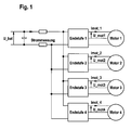
- Fig. 1 of the drawing shows a system diagram with several at a common Power connected motors, engine 1, engine 2, engine 3 and engine 4, respectively own, with power amplifier 1, power amplifier 2, power amplifier 3 and power amplifier 4 designated control circuits have.
- IDC_g denotes the total current of the device, it is readily apparent that IDC_g corresponds to the motor current of the motor 1 lmot_1 when the engine 2, motor 3 and Motor 4 are not energized. It means in other words that in a period of time, to which the motor 2, the motor 3 and the motor 4 are currently not energized by means of the current measurement made by the power amplifier 1, the current value in the Electricity, connection elements, power amplifier 1 and engine 1 can be measured, the Motor string current Imot_1 corresponds.
- the current flowing in the final stage 2 and the motor 2 corresponds to the current Imot_2 measured by the power amplifier 2 total current IDC_g when the engine 1, the engine 3 and the motor 4 are currently not energized.
- I_mot Motor terminal voltage - Counter-induced motor voltage total impedance
- L corresponds to the motor inductance and p corresponds to the motor pole pair number.
- I_mot I_mess / PWM_ist ie
- the motor string current I_mot results as a quotient of the measured current value I_mess and the actual duty cycle PWM_act.
- the total resistance of the respective current path can then be determined when the Current value of the individual current path has been measured, so measured a current value was and during the measurement the other engines were not energized, so that the measured total current value IDC_g the respective measured current value I_mess corresponds.
- the achievable accuracy of this current control is determined by the individual parameters determined and the accuracy of the current measurement.
- the motor constant can also be used - as part of a certain simplification - as constant value can be assumed in the current control, which admittedly to certain, however possibly still tolerable errors in the respective application.
- the inventive method for limiting of the current value can be applied in a current path at which the electric motor a Actuator motor of a clutch or an automated transmission of a motor vehicle is.
- the electric motor for example, an actuating motor for the coupling of a automated gearbox
- an adjustment process can then be performed if the switching or selection motor of the gearbox is not energized.
- a Current measurement at high traversing speed of the clutch ie high load condition of the clutch Clutch actuation motor preferable, or states where the speed of the electric motor ( ⁇ ) is close to or equal to zero.
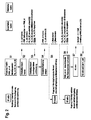
- a first step S1 the clutch 2 is inactive and the actual duty cycle (PWM_ist) of the The motor assigned to the clutch 2 is 0.
- PWM_ist the actual duty cycle
- the total resistance is the current path with the clutch 2 associated engine known as well the motor constant, i. So Rg_ist_K2 is known and Ke_ist_K2 is also known.
- a stop is started in a speed-controlled manner and can, For example, be recognized by a sudden increase in the measured strand current.
- a next step S4 an actual motor duty ratio PWM_act is set and the Speed ⁇ _is determined by the motor, which is approximately 0 due to the stop.
- the current value measurement is performed.
- the Total resistance of the current path of the clutch K2 associated engine, its control shaft and all connection elements and the like are determined. is the thus determined total resistance of this current section within a boundary window (the calculated total resistance can be so plausibilized) is the total resistance Rg_ist_K2 and can be used in the determination of the current value for subsequent periods incorporated.
- the clutch K2 be activated again and be performed on the basis of the actuating motor of the clutch K2 Force or its torque to be provided is the target engine train current I_soll determines what the target motor load ratio PWM_soll is based on the above Equation [G5] can be determined.
- the clutch K2 is again active and the model adjusted (step S8).
- the total resistance also changes. This can not be determined constantly by the current measurement.
- the temperature is determined, which is the current range at the time of current measurement Has.
- About a temperature correction coefficient of the temperature-dependent Total resistance then starting from the current actual resistance until the next current measurement be calculated.
- the next current measurement is then again the current calculated value adjusted to the measured resistance.
- the total resistance of the Current path is made up of the resistances of the individual components of the current path together, so the resistance of the control circuit, the resistance of the electric motor and the resistance of all connection elements, such as leads, plugs, Bushings, etc. in the power line.
- the temperature-dependent total resistance of the current path can then in time intervals be compensated for temperature between adjustments by the calculated total resistance is corrected with the correction factor determined from the equation [G9].
- the total resistance thus corrected is the basis for the determination of the current value for a new period of time.
Landscapes
- Engineering & Computer Science (AREA)
- Power Engineering (AREA)
- Life Sciences & Earth Sciences (AREA)
- Sustainable Development (AREA)
- Sustainable Energy (AREA)
- Transportation (AREA)
- Mechanical Engineering (AREA)
- Control Of Electric Motors In General (AREA)
- Electric Propulsion And Braking For Vehicles (AREA)
- Control Of Direct Current Motors (AREA)
Applications Claiming Priority (2)
| Application Number | Priority Date | Filing Date | Title |
|---|---|---|---|
| DE10342445 | 2003-09-13 | ||
| DE10342445 | 2003-09-13 |
Publications (2)
| Publication Number | Publication Date |
|---|---|
| EP1514723A2 true EP1514723A2 (fr) | 2005-03-16 |
| EP1514723A3 EP1514723A3 (fr) | 2006-09-20 |
Family
ID=34129805
Family Applications (1)
| Application Number | Title | Priority Date | Filing Date |
|---|---|---|---|
| EP04020812A Withdrawn EP1514723A3 (fr) | 2003-09-13 | 2004-09-02 | Procédé de contrôle d'un circuit de contrôle et du courant à travers des dispositifs branchés, d'une ligne électrifiée |
Country Status (2)
| Country | Link |
|---|---|
| EP (1) | EP1514723A3 (fr) |
| DE (1) | DE102004042403B4 (fr) |
Cited By (2)
| Publication number | Priority date | Publication date | Assignee | Title |
|---|---|---|---|---|
| RU2423714C1 (ru) * | 2010-01-27 | 2011-07-10 | Государственное образовательное учреждение высшего профессионального образования Омский государственный университет путей сообщения | Классификатор технического состояния электрической системы пропуска обратного тягового тока |
| CN113872496A (zh) * | 2021-09-27 | 2021-12-31 | 重庆长安新能源汽车科技有限公司 | 一种用汽车电驱动系统的电机控制方法、系统及车辆 |
Family Cites Families (7)
| Publication number | Priority date | Publication date | Assignee | Title |
|---|---|---|---|---|
| JPS52155717A (en) * | 1976-06-18 | 1977-12-24 | Agency Of Ind Science & Technol | Automatic transmission system for electric vehicle |
| JPH0687642B2 (ja) * | 1986-12-15 | 1994-11-02 | 株式会社日立製作所 | 回転電機の回転子巻線異常診断装置 |
| JP3230831B2 (ja) * | 1992-01-28 | 2001-11-19 | オークマ株式会社 | モータ駆動制御装置 |
| DE4211183A1 (de) * | 1992-04-03 | 1993-10-07 | Bosch Gmbh Robert | Umrichter mit Zwischenkreismonitor |
| US5291128A (en) * | 1992-05-19 | 1994-03-01 | General Motors Corporation | Motor testing apparatus utilizing inertial loading |
| DE4330537B4 (de) * | 1993-09-09 | 2006-06-01 | Robert Bosch Gmbh | Frequenzumrichter und Verfahren zu seinem Betrieb |
| FR2806551B1 (fr) * | 2000-03-15 | 2002-05-10 | Valeo Electronique | Procedes et dispositifs pour le suivi de la rotation de moteurs electriques a courant continu |
-
2004
- 2004-09-02 DE DE102004042403.9A patent/DE102004042403B4/de not_active Expired - Fee Related
- 2004-09-02 EP EP04020812A patent/EP1514723A3/fr not_active Withdrawn
Cited By (3)
| Publication number | Priority date | Publication date | Assignee | Title |
|---|---|---|---|---|
| RU2423714C1 (ru) * | 2010-01-27 | 2011-07-10 | Государственное образовательное учреждение высшего профессионального образования Омский государственный университет путей сообщения | Классификатор технического состояния электрической системы пропуска обратного тягового тока |
| CN113872496A (zh) * | 2021-09-27 | 2021-12-31 | 重庆长安新能源汽车科技有限公司 | 一种用汽车电驱动系统的电机控制方法、系统及车辆 |
| CN113872496B (zh) * | 2021-09-27 | 2023-07-21 | 深蓝汽车科技有限公司 | 一种用汽车电驱动系统的电机控制方法、系统及车辆 |
Also Published As
| Publication number | Publication date |
|---|---|
| EP1514723A3 (fr) | 2006-09-20 |
| DE102004042403A1 (de) | 2005-04-07 |
| DE102004042403B4 (de) | 2020-02-06 |
Similar Documents
| Publication | Publication Date | Title |
|---|---|---|
| DE10151177B4 (de) | Vorrichtung zur Steuerung einer mittels eines Motors betriebenen Servolenkeinrichtung | |
| EP1413044B1 (fr) | Procede pour faire fonctionner un moteur a commutation electronique et moteur pour la mise en oeuvre dudit procede | |
| EP2377239B1 (fr) | Procédé de détection de panne pour des moteurs électriques comportant un ou plusieurs points neutres | |
| DE3608603C2 (de) | Überwachungs- und Steuereinrichtung für ein Elektrofahrzeug | |
| DE112015000861T5 (de) | Antriebssteuerung und Verfahren zur Antriebssteuerung eines Elektromotors | |
| DE19510394A1 (de) | Von einem Gleichstrommotor angetriebene Servolenkanlage für ein Kraftfahrzeug | |
| DE4125302A1 (de) | Einrichtung zur ueberwachung eines elektrischen verbrauchers in einem fahrzeug | |
| DE10035356B4 (de) | Vorrichtung zur elektrischen Servolenkung | |
| DE102006052423B4 (de) | Servolenkungsvorrichtung | |
| DE69517920T2 (de) | Elektrische Servolenkung | |
| DE102005023456A1 (de) | Elektronische Steuereinheit, elektrisch unterstützte Lenkvorrichtung und Lenkeinheit mit variablem Übersetzungsverhältnis | |
| DE3690376C2 (fr) | ||
| DE19504435A1 (de) | Stromservoverstärkungs-/-steuerungsapparat und Verfahren für umkehrbare Gleichstrommotoren | |
| EP0224689A1 (fr) | Dispositif pour contrôler la température des moteurs shunt à courant continu pour presses rotatives à imprimer | |
| DE112008000522T5 (de) | Bestimmung des von einem Motor gezogenen Durchschnittsstroms | |
| EP1514723A2 (fr) | Procédé de contrôle d'un circuit de contrôle et du courant à travers des dispositifs branchés, d'une ligne électrifiée | |
| WO2020152077A1 (fr) | Procédé permettant de séparer d'une source de tension continue un moteur électrique polyphasé d'une direction assistée électromécanique d'un véhicule à moteur et unité de commande servant à l'activation du moteur électrique | |
| DE112016003094T5 (de) | Elektrowerkzeug und Verfahren zum Antreiben eines bürstenlosen Motors des Elektrowerkzeuges | |
| DE112015004348T5 (de) | Motorsteuervorrichtung und motorsteuerverfahren | |
| DE102017108473A1 (de) | Verfahren zur Kontrolle eines elektrischen Antriebs eines Fahrzeugs | |
| DE102020134718A1 (de) | Steuervorrichtung und steuerverfahren | |
| EP2148978B1 (fr) | Procédé de rétrosignalisation d'états d'un composant électrique à une commande moteur d'un moteur à combustion interne | |
| DE112014003924T5 (de) | Überstromermittlungsvorrichtung und Überstromermittlungsverfahren | |
| DE102009041451B4 (de) | Ansteuereinheit für elektrische und/oder pneumatische Verstellantriebe | |
| EP1948925A1 (fr) | Unité à bougie-crayon de préchauffage et système de commande d une pluralité de bougies-crayons de préchauffage |
Legal Events
| Date | Code | Title | Description |
|---|---|---|---|
| PUAI | Public reference made under article 153(3) epc to a published international application that has entered the european phase |
Free format text: ORIGINAL CODE: 0009012 |
|
| AK | Designated contracting states |
Kind code of ref document: A2 Designated state(s): AT BE BG CH CY CZ DE DK EE ES FI FR GB GR HU IE IT LI LU MC NL PL PT RO SE SI SK TR |
|
| AX | Request for extension of the european patent |
Extension state: AL HR LT LV MK |
|
| PUAL | Search report despatched |
Free format text: ORIGINAL CODE: 0009013 |
|
| AK | Designated contracting states |
Kind code of ref document: A3 Designated state(s): AT BE BG CH CY CZ DE DK EE ES FI FR GB GR HU IE IT LI LU MC NL PL PT RO SE SI SK TR |
|
| AX | Request for extension of the european patent |
Extension state: AL HR LT LV MK |
|
| RIC1 | Information provided on ipc code assigned before grant |
Ipc: G01R 31/02 20060101ALI20060817BHEP Ipc: G01R 31/06 20060101ALI20060817BHEP Ipc: G01R 31/34 20060101ALI20060817BHEP Ipc: H02P 7/29 20060101ALI20060817BHEP Ipc: H02P 7/285 20060101ALI20060817BHEP Ipc: H02P 6/00 20060101ALI20060817BHEP Ipc: B60L 15/20 20060101AFI20050110BHEP |
|
| 17P | Request for examination filed |
Effective date: 20070320 |
|
| AKX | Designation fees paid |
Designated state(s): AT BE BG CH CY CZ DE DK EE ES FI FR GB GR HU IE IT LI LU MC NL PL PT RO SE SI SK TR |
|
| 17Q | First examination report despatched |
Effective date: 20091029 |
|
| STAA | Information on the status of an ep patent application or granted ep patent |
Free format text: STATUS: THE APPLICATION IS DEEMED TO BE WITHDRAWN |
|
| 18D | Application deemed to be withdrawn |
Effective date: 20100309 |
|
| P01 | Opt-out of the competence of the unified patent court (upc) registered |
Effective date: 20230523 |