EP1514723A2 - Method to control a control circuit and the current running through connected devices of an electrified track with an electrical motor - Google Patents
Method to control a control circuit and the current running through connected devices of an electrified track with an electrical motor Download PDFInfo
- Publication number
- EP1514723A2 EP1514723A2 EP04020812A EP04020812A EP1514723A2 EP 1514723 A2 EP1514723 A2 EP 1514723A2 EP 04020812 A EP04020812 A EP 04020812A EP 04020812 A EP04020812 A EP 04020812A EP 1514723 A2 EP1514723 A2 EP 1514723A2
- Authority
- EP
- European Patent Office
- Prior art keywords
- current
- motor
- total resistance
- determined
- control circuit
- Prior art date
- Legal status (The legal status is an assumption and is not a legal conclusion. Google has not performed a legal analysis and makes no representation as to the accuracy of the status listed.)
- Withdrawn
Links
Images
Classifications
-
- H—ELECTRICITY
- H02—GENERATION; CONVERSION OR DISTRIBUTION OF ELECTRIC POWER
- H02P—CONTROL OR REGULATION OF ELECTRIC MOTORS, ELECTRIC GENERATORS OR DYNAMO-ELECTRIC CONVERTERS; CONTROLLING TRANSFORMERS, REACTORS OR CHOKE COILS
- H02P5/00—Arrangements specially adapted for regulating or controlling the speed or torque of two or more electric motors
- H02P5/74—Arrangements specially adapted for regulating or controlling the speed or torque of two or more electric motors controlling two or more ac dynamo-electric motors
-
- B—PERFORMING OPERATIONS; TRANSPORTING
- B60—VEHICLES IN GENERAL
- B60L—PROPULSION OF ELECTRICALLY-PROPELLED VEHICLES; SUPPLYING ELECTRIC POWER FOR AUXILIARY EQUIPMENT OF ELECTRICALLY-PROPELLED VEHICLES; ELECTRODYNAMIC BRAKE SYSTEMS FOR VEHICLES IN GENERAL; MAGNETIC SUSPENSION OR LEVITATION FOR VEHICLES; MONITORING OPERATING VARIABLES OF ELECTRICALLY-PROPELLED VEHICLES; ELECTRIC SAFETY DEVICES FOR ELECTRICALLY-PROPELLED VEHICLES
- B60L3/00—Electric devices on electrically-propelled vehicles for safety purposes; Monitoring operating variables, e.g. speed, deceleration or energy consumption
- B60L3/04—Cutting off the power supply under fault conditions
-
- H—ELECTRICITY
- H02—GENERATION; CONVERSION OR DISTRIBUTION OF ELECTRIC POWER
- H02P—CONTROL OR REGULATION OF ELECTRIC MOTORS, ELECTRIC GENERATORS OR DYNAMO-ELECTRIC CONVERTERS; CONTROLLING TRANSFORMERS, REACTORS OR CHOKE COILS
- H02P6/00—Arrangements for controlling synchronous motors or other dynamo-electric motors using electronic commutation dependent on the rotor position; Electronic commutators therefor
- H02P6/34—Modelling or simulation for control purposes
-
- Y—GENERAL TAGGING OF NEW TECHNOLOGICAL DEVELOPMENTS; GENERAL TAGGING OF CROSS-SECTIONAL TECHNOLOGIES SPANNING OVER SEVERAL SECTIONS OF THE IPC; TECHNICAL SUBJECTS COVERED BY FORMER USPC CROSS-REFERENCE ART COLLECTIONS [XRACs] AND DIGESTS
- Y02—TECHNOLOGIES OR APPLICATIONS FOR MITIGATION OR ADAPTATION AGAINST CLIMATE CHANGE
- Y02T—CLIMATE CHANGE MITIGATION TECHNOLOGIES RELATED TO TRANSPORTATION
- Y02T10/00—Road transport of goods or passengers
- Y02T10/60—Other road transportation technologies with climate change mitigation effect
- Y02T10/64—Electric machine technologies in electromobility
-
- Y—GENERAL TAGGING OF NEW TECHNOLOGICAL DEVELOPMENTS; GENERAL TAGGING OF CROSS-SECTIONAL TECHNOLOGIES SPANNING OVER SEVERAL SECTIONS OF THE IPC; TECHNICAL SUBJECTS COVERED BY FORMER USPC CROSS-REFERENCE ART COLLECTIONS [XRACs] AND DIGESTS
- Y02—TECHNOLOGIES OR APPLICATIONS FOR MITIGATION OR ADAPTATION AGAINST CLIMATE CHANGE
- Y02T—CLIMATE CHANGE MITIGATION TECHNOLOGIES RELATED TO TRANSPORTATION
- Y02T10/00—Road transport of goods or passengers
- Y02T10/60—Other road transportation technologies with climate change mitigation effect
- Y02T10/72—Electric energy management in electromobility
Definitions
- the present invention relates to a method for controlling the in a current path with an electric motor and a control circuit and connecting elements in a period of time flowing stream according to the preamble of claim 1.
- Electric motors are usually controlled by a control circuit to the Actuation of the driven by the electric motor components the requirement-specific profiles to control the components accordingly.
- connection elements in the form of plug and socket connections and connecting cables and the like.
- the control circuit and the electric motor are fed from a power source, so that also from the power source to the mentioned Consumers corresponding connection elements are present.
- controller time slice is essential is smaller than the electrical time constant, so this requires costly measures in the form of additional electronic components and complex motor current measurements.
- the present invention is based on the object of such a method to reduce the effort required to control and limit the flow can be.
- the invention now provides a solution to this problem, a method for controlling the in one Electric circuit with an electric motor and a control circuit and connection elements flowing in a period of time, wherein the method using a in a first time segment measured current value of the total resistance of the current path determined and the motor string current of a subsequent second time period based on the Total resistance and a target motor strand current is controlled.
- first and second time periods are different from each other, do not necessarily have to follow each other directly.
- Procedure first a current value is measured and from this the total resistance of the Electricity range determined. On the basis of these then known characteristics of the motor string current a subsequent period of time based on the total resistance and a Solmotorstrangstroms controlled.
- Method of measured total resistance of the current section for determination the motor string current is used, so that with this control of the motor string current for example, can be determined for several periods of time until due the application specific given conditions gives an opportunity that Measure current value a next time and from this the total resistance a next time which in turn is then used as the output value for the determination of the current value in again subsequent period of time is used, so that with even in irregular Time intervals possible new determination of the total resistance again Output value for determining the motor string current to be determined below Is available and thus an adjustment is possible.
- the equation with Rg_ist is based on the measured current value of a previous period known total resistance in the Determination of the motor load ratio and with L the motor inductance, p the number of motor pole pairs, ⁇ the rotor speed with directional sign and ke the motor constant, with U_bat is the supply voltage of the control circuit.
- the total resistance of the current path is determined on the basis of the measured current value which may then be included in the determination of the next or subsequent periods, until a further adjustment of the total resistance, in the determination of the Motor string current is received.
- the total resistance determined by the method according to the invention is according to the invention as long as total resistance to control the Motor string current used until by a comparison process, a new total resistance is determined.
- the temperature correction coefficient as the quotient of a measured total resistance and a calculated one Total resistance is determined. This makes it possible to change temperature of the total resistance by determining a total resistance is calculated as the sum of the resistances of the connecting elements as well as the control circuit and the Electric motor, i. So all in the current path causing a resistance Components, components, components and the like. This calculated total resistance is compared with a measured total resistance measured from a current measurement and thus goes into the correction of total resistance in periods between individuals Adjustments on.
- the measurement of the current value with a current measuring device of the control circuit is made.
- the control circuit can have a short-circuit protection function to avoid a short circuit, with the current current values can be measured, which then make up the total resistance determine the current path.
- the inventive method can be used to limit the in an electric motor and Its control circuit can use flowing electricity and can also be used for system monitoring be used, since, for example, be known empirically determined can that the motor parameters of the electric motor only within certain windows, i. ie limits, and may therefore change the limit values by the motor parameters suggesting that in the electric drive, in which the electric motor integrated is, an error has crept in or the drive is no longer working properly, which, for example, can be derived from that over subsequent periods of time results in a long-term trend in the direction of the permissible limits or windows of the engine parameters and thus the future occurrence of an error is likely.
- the method for determining the in a current path with an electric motor and a control circuit and connection elements flowing current is applied, wherein the electric motor is an actuating motor of a Clutch or an actuating motor of an automated transmission of a vehicle is.
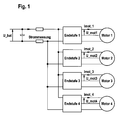
- Fig. 1 of the drawing shows a system diagram with several at a common Power connected motors, engine 1, engine 2, engine 3 and engine 4, respectively own, with power amplifier 1, power amplifier 2, power amplifier 3 and power amplifier 4 designated control circuits have.
- IDC_g denotes the total current of the device, it is readily apparent that IDC_g corresponds to the motor current of the motor 1 lmot_1 when the engine 2, motor 3 and Motor 4 are not energized. It means in other words that in a period of time, to which the motor 2, the motor 3 and the motor 4 are currently not energized by means of the current measurement made by the power amplifier 1, the current value in the Electricity, connection elements, power amplifier 1 and engine 1 can be measured, the Motor string current Imot_1 corresponds.
- the current flowing in the final stage 2 and the motor 2 corresponds to the current Imot_2 measured by the power amplifier 2 total current IDC_g when the engine 1, the engine 3 and the motor 4 are currently not energized.
- I_mot Motor terminal voltage - Counter-induced motor voltage total impedance
- L corresponds to the motor inductance and p corresponds to the motor pole pair number.
- I_mot I_mess / PWM_ist ie
- the motor string current I_mot results as a quotient of the measured current value I_mess and the actual duty cycle PWM_act.
- the total resistance of the respective current path can then be determined when the Current value of the individual current path has been measured, so measured a current value was and during the measurement the other engines were not energized, so that the measured total current value IDC_g the respective measured current value I_mess corresponds.
- the achievable accuracy of this current control is determined by the individual parameters determined and the accuracy of the current measurement.
- the motor constant can also be used - as part of a certain simplification - as constant value can be assumed in the current control, which admittedly to certain, however possibly still tolerable errors in the respective application.
- the inventive method for limiting of the current value can be applied in a current path at which the electric motor a Actuator motor of a clutch or an automated transmission of a motor vehicle is.
- the electric motor for example, an actuating motor for the coupling of a automated gearbox
- an adjustment process can then be performed if the switching or selection motor of the gearbox is not energized.
- a Current measurement at high traversing speed of the clutch ie high load condition of the clutch Clutch actuation motor preferable, or states where the speed of the electric motor ( ⁇ ) is close to or equal to zero.
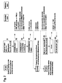
- a first step S1 the clutch 2 is inactive and the actual duty cycle (PWM_ist) of the The motor assigned to the clutch 2 is 0.
- PWM_ist the actual duty cycle
- the total resistance is the current path with the clutch 2 associated engine known as well the motor constant, i. So Rg_ist_K2 is known and Ke_ist_K2 is also known.
- a stop is started in a speed-controlled manner and can, For example, be recognized by a sudden increase in the measured strand current.
- a next step S4 an actual motor duty ratio PWM_act is set and the Speed ⁇ _is determined by the motor, which is approximately 0 due to the stop.
- the current value measurement is performed.
- the Total resistance of the current path of the clutch K2 associated engine, its control shaft and all connection elements and the like are determined. is the thus determined total resistance of this current section within a boundary window (the calculated total resistance can be so plausibilized) is the total resistance Rg_ist_K2 and can be used in the determination of the current value for subsequent periods incorporated.
- the clutch K2 be activated again and be performed on the basis of the actuating motor of the clutch K2 Force or its torque to be provided is the target engine train current I_soll determines what the target motor load ratio PWM_soll is based on the above Equation [G5] can be determined.
- the clutch K2 is again active and the model adjusted (step S8).
- the total resistance also changes. This can not be determined constantly by the current measurement.
- the temperature is determined, which is the current range at the time of current measurement Has.
- About a temperature correction coefficient of the temperature-dependent Total resistance then starting from the current actual resistance until the next current measurement be calculated.
- the next current measurement is then again the current calculated value adjusted to the measured resistance.
- the total resistance of the Current path is made up of the resistances of the individual components of the current path together, so the resistance of the control circuit, the resistance of the electric motor and the resistance of all connection elements, such as leads, plugs, Bushings, etc. in the power line.
- the temperature-dependent total resistance of the current path can then in time intervals be compensated for temperature between adjustments by the calculated total resistance is corrected with the correction factor determined from the equation [G9].
- the total resistance thus corrected is the basis for the determination of the current value for a new period of time.
Abstract
Description
Die vorliegende Erfindung betrifft ein Verfahren zur Steuerung des in einer Stromstrecke mit einem Elektromotor und einer Steuerschaltung sowie Anschlusselementen in einem Zeitabschnitt fließenden Stroms nach dem Oberbegriff des Anspruches 1.The present invention relates to a method for controlling the in a current path with an electric motor and a control circuit and connecting elements in a period of time flowing stream according to the preamble of claim 1.
Elektromotoren werden üblicherweise mit einer Steuerschaltung angesteuert, um die Betätigung der vom Elektromotor angetriebenen Bauteile den anforderungsspezifischen Profilen der Bauteile entsprechend anzusteuern. Zwischen der Steuerung und dem Elektromotor sind Anschlusselemente in der Form von Stecker- und Buchsenverbindungen und Anschlussleitungen und dergleichen vorgesehen. Die Steuerschaltung sowie der Elektromotor werden aus einer Stromquelle gespeist, so dass auch von der Stromquelle zu den genannten Verbrauchern entsprechende Anschlusselemente vorliegen. Zum Schutz der in der Steuerschaltung regelmäßig vorhandenen Leistungstransistoren sowie der gesamten Stromstrecke ist es erforderlich, den vom Elektromotor aufgenommenen Strom zu begrenzen.Electric motors are usually controlled by a control circuit to the Actuation of the driven by the electric motor components the requirement-specific profiles to control the components accordingly. Between the controller and the electric motor are connection elements in the form of plug and socket connections and connecting cables and the like. The control circuit and the electric motor are fed from a power source, so that also from the power source to the mentioned Consumers corresponding connection elements are present. To protect the in the control circuit regularly available power transistors and the entire current path it is necessary to limit the current absorbed by the electric motor.
Nicht anders verhält es sich, wenn der Elektromotor Teil einer Antriebskette zur Betätigung der Kupplung und/oder des Getriebes eines Kraftfahrzeugs ist. In einem solchen Anwendungsfall kommt ergänzend noch hinzu, dass die Stromstrecke aufgrund der unterschiedichen Betriebszustände des Kraftfahrzeugs starken Temperaturschwankungen unterworfen ist, wodurch sich auch die in der Stromstrecke auftretenden elektrischen Widerstände erheblich verändern. Diese temperaturabhängige Veränderung der Widerstände führt nun auch dazu, dass die von den Leistungstransistoren der Steuerschaltung geschalteten Stromwerte nicht nur vom Elektromotor induzierten lastabhängigen Veränderungen unterworfen sind, sondern auch temperaturbedingten Veränderungen.The situation is different if the electric motor is part of a drive chain for actuation the clutch and / or the transmission of a motor vehicle. In such an application Complementing that is the fact that the current range differs due to the difference Operating conditions of the motor vehicle is subject to severe temperature fluctuations, which also considerably affects the electrical resistances occurring in the current path change. This temperature-dependent change in resistance now also leads to that the current values switched by the power transistors of the control circuit are not are only subjected to load-dependent changes induced by the electric motor, but also temperature-related changes.
Diese Schilderung macht deutlich, dass der Motorstrom zum Schutz der Leistungstransistoren sowie der Belastung des Bordnetzes eines Kraftfahrzeugs wegen Temperaturabhängigkeiten und kleinen variablen Motorwiderstandswerten kontrolliert und begrenzt werden muss.This description makes it clear that the motor current to protect the power transistors and the load on the electrical system of a motor vehicle because of temperature dependencies and small variable engine resistance values must be controlled and limited.
Um diese Problematik in den Griff zu bekommen, ist es nun grundsätzlich möglich, eine Stromregelung vorzusehen, die aber voraussetzt, dass die Reglerzeitscheibe um ein mehrfaches kleiner ist als die elektrische Zeitkonstante des Antriebs L/R, wobei mit L die Induktivität und R der Gesamtwiderstand bezeichnet werden.In order to get this problem under control, it is now possible in principle, a Provide current control, but requires that the controller disk by a multiple is less than the electrical time constant of the drive L / R, where L is the inductance and R is the total resistance.
Wenn nun diese Voraussetzungen nicht erfüllt ist, dass die Reglerzeitscheibe wesentlich kleiner ist als die elektrische Zeitkonstante, so erfordert dies kostenaufwendige Maßnahmen in der Form zusätzlicher elektronischer Komponenten und aufwendiger Motorstrommessungen.If now these requirements are not met, the controller time slice is essential is smaller than the electrical time constant, so this requires costly measures in the form of additional electronic components and complex motor current measurements.
Im vorstehend geschilderten Anwendungsfall der Verwendung eines Elektromotors zur Betätigung der Kupplung oder des Getriebes eines Kraftfahrzeugs befinden sich regelmäßig mehrere Elektromotoren in der Stromstrecke, so dass die genannten Motorstrommessungen an den einzelnen Elektromotoren durchgeführt werden müssten, was den Aufwand selbstverständlich erhöht.In the above-described application of the use of an electric motor for Operation of the clutch or the transmission of a motor vehicle are regularly several electric motors in the power line, so that said motor current measurements would have to be performed on the individual electric motors, which the effort of course elevated.
Zur Verringerung des Aufwands wäre es daher möglich, den in der Stromstrecke zulässigen Stromwert auf einen einstellbaren Wert zu begrenzen, wobei aber dann nach wie vor für jeden einzelnen Elektromotor eine eigene Strommessung implementiert werden müsste.To reduce the effort, it would therefore be possible, the permissible in the power line Current limit to an adjustable value limit, but then still for everyone individual electric motor a separate current measurement would have to be implemented.
Aufgrund von im mechanischen Antriebsstrang des Elektromotors und eines mit diesem etwaig verbundenen Getriebes zur Betätigung beispielsweise eines Parallelschaltgetriebes eines Kraftfahrzeugs vorhandener Toleranzen ändern sich die Stromwerte auch noch aufgrund dieser auch verschleißbedingt sich verändernden Toleranzen zusätzlich, so dass nunmehr deutlich geworden sein dürfte, dass ein entsprechender Bedarf besteht an einem Verfahren zur Steuerung des in einer Stromstrecke mit einem Elektromotor und einer Steuerschaltung sowie Anschlusselementen in einem Zeitabschnitt fließenden Stroms.Due to in the mechanical drive train of the electric motor and one with this possibly connected gear for actuating, for example, a parallel transmission of a Motor vehicle existing tolerances, the current values change due to this also wear-related changing tolerances in addition, so now should have become clear that there is a corresponding need for a procedure for controlling the in a current path with an electric motor and a control circuit and terminal elements in a period of time flowing current.
Der vorliegenden Erfindung liegt nunmehr die Aufgabe zugrunde, ein derartiges Verfahren zu schaffen, mit dem der zur Steuerung und Begrenzung des Stroms erforderliche Aufwand verringert werden kann.The present invention is based on the object of such a method to reduce the effort required to control and limit the flow can be.
Die Erfindung schafft nun zur Lösung dieser Aufgabe ein Verfahren zur Steuerung des in einer Stromstrecke mit einem Elektromotor und einer Steuerschaltung sowie Anschlusselementen in einem Zeitabschnitt fließenden Stroms, wobei nach dem Verfahren anhand eines in einem ersten Zeitabschnitt gemessenen Stromwerts der Gesamtwiderstand der Stromstrecke bestimmt wird und der Motorstrangstrom eines folgenden zweiten Zeitabschnitts anhand des Gesamtwiderstands und eines Sollmotorstrangsstroms gesteuert wird. The invention now provides a solution to this problem, a method for controlling the in one Electric circuit with an electric motor and a control circuit and connection elements flowing in a period of time, wherein the method using a in a first time segment measured current value of the total resistance of the current path determined and the motor string current of a subsequent second time period based on the Total resistance and a target motor strand current is controlled.
Die vorstehend definierten ersten und zweiten Zeitabschnitte unterscheiden sich voneinander, müssen nicht aber notwendigerweise direkt aufeinander folgen. Mit dem erfindungsgemäßen Verfahren wird zunächst ein Stromwert gemessen und daraus der Gesamtwiderstand der Stromstrecke bestimmt. Auf der Basis dieser dann bekannten Kenngrößen wird der Motorstrangstrom eines folgenden Zeitabschnitts anhand des Gesamtwiderstands und eines Solmotorstrangstroms gesteuert. Es bedeutet dies mit anderen Worten, dass mit dem erfindungsgemäßen Verfahren der gemessene Gesamtwiderstand der Stromstrecke zur Bestimmung des Motorstrangstroms herangezogen wird, so dass mit dieser Steuerung der Motorstrangstrom für beispielsweise mehrere Zeitabschnitte bestimmt werden kann, bis sich aufgrund der anwendungsspezifisch gegebenen Voraussetzungen eine Gelegenheit gibt, den Stromwert ein nächstes Mal zu messen und daraus den Gesamtwiderstand ein nächstes Mal zu bestimmen, der dann wiederum als Ausgangswert für die Bestimmung des Stromwertes in wiederum darauf folgenden Zeitabschnitt verwendet wird, so dass mit der auch in unregelmäßigen Zeitabständen möglichen neuen Bestimmung des Gesamtwiderstandes wieder ein Ausgangswert für die Bestimmung des nachfolgend festzulegenden Motorstrangstroms zur Verfügung steht und somit ein Abgleich möglich ist.The above-defined first and second time periods are different from each other, do not necessarily have to follow each other directly. With the invention Procedure, first a current value is measured and from this the total resistance of the Electricity range determined. On the basis of these then known characteristics of the motor string current a subsequent period of time based on the total resistance and a Solmotorstrangstroms controlled. It means in other words that with the invention Method of measured total resistance of the current section for determination the motor string current is used, so that with this control of the motor string current for example, can be determined for several periods of time until due the application specific given conditions gives an opportunity that Measure current value a next time and from this the total resistance a next time which in turn is then used as the output value for the determination of the current value in again subsequent period of time is used, so that with even in irregular Time intervals possible new determination of the total resistance again Output value for determining the motor string current to be determined below Is available and thus an adjustment is possible.
Wenn sich nun aufgrund temperaturbedingter Veränderungen der Widerstände der einzelnen Elemente in der Stromstrecke, d.h. also des Elektromotors, der Steuerschaltung, Anschlussleitungen, Steckern, Buchsen und sonstigen Bauteilen in der Stromstrecke, der Gesamtwiderstand der Stromstrecke verändert, dann wird mittels des erfindungsgemäßen Verfahrens die Möglichkeit eines Abgleichs geschaffen, derart, dass Veränderungen des Gesamtwiderstands in das erfindungsgemäße Steuerverfahren einfließen und somit einerseits temperaturbedingten Veränderungen des Gesamtwiderstands Rechnung getragen werden kann als auch Veränderungen in der mechanischen Übertragungsstrecke, also beispielsweise Veränderungen der einzelnen Bauteiltoleranzen, da diese Veränderungen zu Veränderungen der gemessenen Stromwerte führen, was wiederum zu einer Veränderung des Gesamtwiderstandes führt und somit mit dem erfindungsgemäßen Verfahren nicht nur temperaturbedingten Veränderungen des Gesamtwiderstands, sondern auch Toleranzveränderungen, beispielsweise verschleißbedingten Veränderungen in der mechanischen Übertragungsstrecke vom Elektrorrotor, über das angeschlossene Getriebe, bis beispielsweise zur Kupplung oder dem Parallelschaltgetriebe des Fahrzeugs Rechnung getragen werden kann.If now due to temperature changes of the resistances of the individual Elements in the current path, i. So the electric motor, the control circuit, connecting cables, Plugs, sockets and other components in the current path, the total resistance the current path is changed, then by means of the method according to the invention the Possibility of reconciliation created such that changes in total resistance to flow into the control method according to the invention and thus on the one hand temperature-related Changes in overall resistance can be accounted for as well as changes in the mechanical transmission path, so for example changes the individual component tolerances, as these changes to changes in the measured Current values lead, which in turn leads to a change in the total resistance and thus with the method according to the invention not only temperature-induced changes the total resistance, but also tolerance changes, such as wear-related Changes in the mechanical transmission path from the electric rotor, via the connected gearbox, for example to the clutch or the parallel gearbox of the vehicle.
Dabei kann der Motorstrangstrom des zweiten oder folgender Zeitabschnitte mittels des
Motortastverhältnisses anhand folgender Beziehung bestimmt werden:
Es bedeutet dies mit anderen Worten, dass anhand der für die Bewältigung der jeweiligen Aufgabe des Elektromotors benötigten Motorkraft bzw. des vom Motor abzugebenden Sollmotormoments und dem daraus sich ergebenden Sollmotorstrangstrom I_soll das für die Bereitstellung des erforderlichen Motormoments notwendige Motortastverhältnis PWM_soll nach der vorstehend wiedergegebenen Gleichung ermittelt werden kann.In other words, that means using it for coping with each one Task of the electric motor required engine power or to be delivered by the engine target engine torque and the resulting target engine train current I_soll for the provision required motor torque required motor duty ratio PWM_soll after the can be determined above equation.
Wie es ohne weiteres ersichtlich ist, geht in die Gleichung mit Rg_ist der anhand des gemessenen Stromwerts eines vorherigen Zeitabschnitts bekannte Gesamtwiderstand in die Ermittlung des Motortastverhältnisses ein sowie mit L die Motorinduktivität, p die Motorpolpaarzahl, ω die Rotordrehzahl mit Richtungsvorzeichen und mit ke die Motorkonstante, mit U_bat wird die Versorgungsspannung der Steuerschaltung bezeichnet. Nach der Erfindung wird auf der Basis des gemessenen Stromwerts der Gesamtwiderstand der Stromstrecke ermittelt werden kann, der dann in die Bestimmung des im nächsten oder folgender Zeitabschnitte, bis zu einem neuerlichen Abgleich des Gesamtwiderstands, in die Bestimmung des Motorstrangstroms eingeht. Der nach dem erfindungsgemäßen Verfahren bestimmte Gesamtwiderstand wird nach der Erfindung solange als Gesamtwiderstand zur Steuerung des Motorstrangstroms verwendet, bis durch einen Abgleichvorgang ein neuer Gesamtwiderstand bestimmt wird.As can be readily appreciated, the equation with Rg_ist is based on the measured current value of a previous period known total resistance in the Determination of the motor load ratio and with L the motor inductance, p the number of motor pole pairs, ω the rotor speed with directional sign and ke the motor constant, with U_bat is the supply voltage of the control circuit. After the invention the total resistance of the current path is determined on the basis of the measured current value which may then be included in the determination of the next or subsequent periods, until a further adjustment of the total resistance, in the determination of the Motor string current is received. The total resistance determined by the method according to the invention is according to the invention as long as total resistance to control the Motor string current used until by a comparison process, a new total resistance is determined.
Wie es schon erläutert wurde, hängt der von den einzelnen Komponenten bzw. Bauteilen in der Stromstrecke dem Stromfluss entgegengebrachte Widerstand von der Temperatur der einzelnen Bauteile bzw. Bestandteile ab.As already explained, depends on the individual components or components in the current path, the current flow supplied resistance of the temperature of individual components or components.
Nach einer Weiterbildung der Erfindung ist es daher vorgesehen, dass der Gesamtwiderstand in Zeitabschnitten zwischen Abgleichvorgängen mittels eines Temperaturkorrekturkoeffizienten korrigiert wird.According to a development of the invention, it is therefore provided that the total resistance in time periods between trimming operations by means of a temperature correction coefficient is corrected.
Es bedeutet dies mit anderen Worten, dass auch zwischen einzelnen Abgleichvorgängen zur Ermittlung eines aktuellen Gesamtwiderstands der Stromstrecke Temperaturveränderungen und sich daraus ergebender Veränderungen der Widerstände der einzelnen Bauteile bzw. Komponenten in der Stromstrecke dadurch Rechnung getragen werden kann, dass der Gesamtwiderstand mittels eines beispielsweise vorab empirisch ermittelten Temperaturkorrekturkoeffizienten korrigiert wird.It means in other words that also between individual adjustment processes for Determination of a current total resistance of the current section temperature changes and resulting changes in the resistances of the individual components or Components in the power line can be accommodated by the total resistance by means of, for example, a previously empirically determined temperature correction coefficient is corrected.
Nach einer Weiterbildung des Verfahrens ist es dabei vorgesehen, dass der Temperaturkorrekturkoeffizient als Quotient eines gemessenen Gesamtwiderstands und eines errechneten Gesamtwiderstands bestimmt wird. Damit ist es möglich, temperaturbedingten Veränderungen des Gesamtwiderstands dadurch Rechnung zu tragen, dass ein Gesamtwiderstand ermittelt wird als Summe der Widerstände der Anschlusselemente sowie der Steuerschaltung und des Elektromotors, d.h. also sämtlicher in der Stromstrecke einen Widerstand hervorrufender Komponenten, Bauteile, Bestandteile und dergleichen. Dieser errechnete Gesamtwiderstand wird mit einem aus einer Strommessung eruierten gemessenen Gesamtwiderstand verglichen und geht so in die Korrektur des Gesamtwiderstands in Zeitabschnitten zwischen einzelnen Abgleichvorgängen ein.According to a development of the method, it is provided that the temperature correction coefficient as the quotient of a measured total resistance and a calculated one Total resistance is determined. This makes it possible to change temperature of the total resistance by determining a total resistance is calculated as the sum of the resistances of the connecting elements as well as the control circuit and the Electric motor, i. So all in the current path causing a resistance Components, components, components and the like. This calculated total resistance is compared with a measured total resistance measured from a current measurement and thus goes into the correction of total resistance in periods between individuals Adjustments on.
Wenn daher an unterschiedlichen Orten der Stromstrecke unterschiedliche Temperaturen herrschen, so ist es möglich, sich den daraus ergebenden unter-schiedlichen temperaturbedingten Veränderungen der Widerstände der einzelnen Bestandteile Rechnung zu tragen. Zu diesem Zweck ist es lediglich erforderlich, dass zur Ermittlung der Widerstände die Temperaturen der Anschlusselemente, der Steuerschaltung und des Elektromotors sowie weiterer Bestandteile, Komponenten, Bauteile und dergleichen in der Stromstrecke zu ermitteln und daraus die Widerstände der einzelnen vorstehend erwähnten Bestandteile der Stromstrecke zu ermitteln.Therefore, if different temperatures occur at different locations of the power path It is thus possible for the resulting different temperature-related Changes in the resistance of the individual components must be taken into account. To For this purpose, it is only necessary that for determining the resistances the temperatures the connection elements, the control circuit and the electric motor and other components, Determine components, components and the like in the current route and from it the resistances of the individual components of the current path mentioned above determine.
Diese so ermittelten Widerstände gehen dann in die Summenbildung des errechneten Gesamtwiderstandes additiv ein.These resistances determined in this way then go into the summation of the calculated one Total resistance additive.
Nach einer Weiterbildung der Erfindung ist es vorgesehen, dass die Messung des Stromwerts mit einer Strommesseinrichtung der Steuerschaltung vorgenommen wird. Die Steuerschaltung kann zur Vermeidung eines Kurzschlusses eine Kurzschlussschutzfunktion besitzen, mit der aktuelle Stromwerte gemessen werden können, aus denen sich dann der Gesamtwiderstand der Stromstrecke bestimmen lässt.According to a development of the invention, it is provided that the measurement of the current value with a current measuring device of the control circuit is made. The control circuit can have a short-circuit protection function to avoid a short circuit, with the current current values can be measured, which then make up the total resistance determine the current path.
Das erfindungsgemäße Verfahren lässt sich zur Begrenzung des in einem Elektromotor und seiner Steuerschaltung fließenden Stroms einsetzen und kann darüber hinaus auch zur Systemüberwachung herangezogen werden, da, beispielsweise empirisch ermittelt bekannt sein kann, dass sich die Motorparameter des Elektromotors nur innerhalb bestimmter Fenster, d.h. also Grenzen, ändern dürfen und somit ein Überschreiten der Grenzwerte durch die Motorparameter darauf hindeutet, dass sich in dem elektrischen Antrieb, in den der Elektromotor integriert ist, ein Fehler eingeschlichen hat bzw. der Antrieb nicht mehr einwandfrei funktioniert, was beispielsweise daraus abgeleitet werden kann, dass sich über nachfolgende Zeitabschnitte ein Langzeittrend in Richtung der zulässigen Grenzen bzw. Fenster der Motorparameter ergibt und somit das künftige Auftreten eines Fehlers wahrscheinlich wird.The inventive method can be used to limit the in an electric motor and Its control circuit can use flowing electricity and can also be used for system monitoring be used, since, for example, be known empirically determined can that the motor parameters of the electric motor only within certain windows, i. ie limits, and may therefore change the limit values by the motor parameters suggesting that in the electric drive, in which the electric motor integrated is, an error has crept in or the drive is no longer working properly, which, for example, can be derived from that over subsequent periods of time results in a long-term trend in the direction of the permissible limits or windows of the engine parameters and thus the future occurrence of an error is likely.
Schließlich ist es nach der Erfindung vorgesehen, dass das Verfahren zur Bestimmung des in einer Stromstrecke mit einem Elektromotor und einer Steuerschaltung sowie Anschlusselementen fließenden Stroms angewandt wird, wobei der Elektromotor ein Betätigungsmotor einer Kupplung oder ein Betätigungsmotor eines automatisierten Getriebes eines Fahrzeugs ist.Finally, it is provided according to the invention that the method for determining the in a current path with an electric motor and a control circuit and connection elements flowing current is applied, wherein the electric motor is an actuating motor of a Clutch or an actuating motor of an automated transmission of a vehicle is.
Die Erfindung wird im folgenden anhand der Zeichnung näher erläutert. Diese zeigt in
- Fig. 1
- ein Systemschaubild mit mehreren an einer gemeinsamen Stromversorgung angeschlossenen Elektromotoren; und
- Fig. 2
- ein schematisches Ablaufdiagramm zur Erläuterung einer Anwendung des erfindungsgemäßen Verfahrens.
- Fig. 1
- a system diagram with multiple electric motors connected to a common power supply; and
- Fig. 2
- a schematic flow diagram for explaining an application of the method according to the invention.
Fig. 1 der Zeichnung zeigt ein Systemschaubild mit mehreren an einer gemeinsamen Stromversorgung angeschlossenen Motoren, Motor 1, Motor 2, Motor 3 und Motor 4, die jeweils eigene, mit Endstufe 1, Endstufe 2, Endstufe 3 und Endstufe 4 bezeichnete Steuerschaltungen besitzen.Fig. 1 of the drawing shows a system diagram with several at a common Power connected motors, engine 1, engine 2, engine 3 and engine 4, respectively own, with power amplifier 1, power amplifier 2, power amplifier 3 and power amplifier 4 designated control circuits have.
Mit U_bat wird die an den einzelnen Steuerschaltungen anliegende Versorgungsspannung bezeichnet und mit IDC_g wird der in der Gesamtstrecke fließende Gesamtstrom bezeichnet.With U_bat, the voltage applied to the individual control circuits supply voltage and IDC_g denotes the total current flowing in the total distance.
Da mit IDC_g der Gesamtstrom der Anordnung bezeichnet ist, ist es ohne weiteres klar, dass IDC_g dem Motorstrangstrom des Motor 1 lmot_1 entspricht, wenn der Motor 2, Motor 3 und Motor 4 nicht bestromt werden. Es bedeutet dies mit anderen Worten, dass in einem Zeitabschnitt, zu dem der Motor 2, der Motor 3 und der Motor 4 gerade nicht bestromt werden, mittels der durch die Endstufe 1 vorgenommenen Strommessung der Stromwert in der Stromstrecke, Anschlusselemente, Endstufe 1 und Motor 1 gemessen werden kann, der dem Motorstrangstrom Imot_1 entspricht.Since IDC_g denotes the total current of the device, it is readily apparent that IDC_g corresponds to the motor current of the motor 1 lmot_1 when the engine 2, motor 3 and Motor 4 are not energized. It means in other words that in a period of time, to which the motor 2, the motor 3 and the motor 4 are currently not energized by means of the current measurement made by the power amplifier 1, the current value in the Electricity, connection elements, power amplifier 1 and engine 1 can be measured, the Motor string current Imot_1 corresponds.
In hierzu ähnlicher Weise entspricht der in der Endstufe 2 und dem Motor 2 fließende Strom Imot_2 dem von der Endstufe 2 gemessenen Gesamtstrom IDC_g, wenn der Motor 1, der Motor 3 und der Motor 4 gerade nicht bestromt werden. Ähnliches gilt auch bezüglich der Motorstrangströme Imot_3 und Imot 4.In a similar manner, the current flowing in the final stage 2 and the motor 2 corresponds to the current Imot_2 measured by the power amplifier 2 total current IDC_g when the engine 1, the engine 3 and the motor 4 are currently not energized. The same applies with regard to the motor string currents Imot_3 and Imot 4.
Ganz allgemein entspricht der im Motor und in der Steuerschaltung fließende Strom I_mot
folgender Beziehung:
Dies heißt mit anderen Worten, dass sich der im Motor und in der Steuerschaltung fließende Strom I_mot bestimmt als der Quotient aus der um die gegeninduzierte Motorspannung reduzierte Motorklemmenspannung und der Gesamtimpedanz.In other words, this means that the current flowing in the motor and in the control circuit Current I_mot is determined as the quotient of the reduced by the counter-induced motor voltage Motor terminal voltage and total impedance.
Als Gesamtimpedanz wird in diesem Fall der Ohmsche Gesamtwiderstand RG und die
Motorinduktivität berücksichtigt, d.h. also
Nach einer vereinfachten Ausführungsform des erfindungsgemäßen Verfahrens wäre es auch möglich, in die Gesamtimpedanz nur den Ohmschen Widerstand Rg einfließen zu lassen und die Motorinduktivität zu vernachlässigen. It would also be according to a simplified embodiment of the method according to the invention possible to include in the total impedance only the ohmic resistance Rg and neglect the motor inductance.
Nachdem nun der gemessene Stromwert I_mess bekannt ist, ergibt sich der Motorstrangstrom
bzw. der in der Steuerschaltung fließende Strom zu:
Die am Motor anliegende Klemmenspannung U_mot ergibt sich als Produkt aus der
Versorgungsspannung der Steuerelektronik und dem Ist-Tastverhältnis, d.h.
Der Gesamtwiderstand der jeweiligen Stromstrecke kann dann bestimmt werden, wenn der Stromwert der einzelnen Stromstrecke gemessen worden ist, also ein Stromwert gemessen wurde und während der Messung die anderen Motoren nicht bestromt wurden, so dass der gemessene Gesamtstromwert IDC_g dem jeweilig gemessenen Stromwert I_mess entspricht.The total resistance of the respective current path can then be determined when the Current value of the individual current path has been measured, so measured a current value was and during the measurement the other engines were not energized, so that the measured total current value IDC_g the respective measured current value I_mess corresponds.
Dann kann für den jeweiligen Motor der aktuelle Gesamtwiderstand der Stromstrecke
berechnet werden mit Berücksichtigung sämtlicher Temperatur- und Toleranzabhängigkeiten,
nämlich
Dies bedeutet mit anderen Worten, dass aufgrund der Messung des Stromwertes der
Gesamtwiderstand der Stromstrecke berechnet werden kann, der dann für die Bestimmung
bzw. Begrenzung des Motorstrangstroms eines folgenden Zeitabschnitts unter Berücksichtigung
des Soll-Motorstrangstroms, der wiederum aus dem jeweiligen Drehmomentenanforderungsprofil
des Motors für den nachfolgenden Zeitabschnitt ermittelt werden kann, bestimmt
werden kann. Es bedeutet dies mit anderen Worten, dass nach Kenntnis des Gesamtwiderstandes
Rg_ist anhand von Gleichung [G4] der Motorstrangstrom anhand des kommenden
Tastverhättnisses PWM_soll auf den von der Steuerschaltung festgelegten Soll-Motorstrangstrom
I_soll, der sämtliche Haupt- und Grenzfunktionen beinhaltet, in Abhängigkeit
von der Drehzahl w gesteuert werden kann, nämlich anhand von Gleichung 5 wie folgt:
Damit wird nun klar, dass der Motorstrangstrom eines folgenden Zeitabschnitts anhand des von der Steuerschaltung bestimmten Soll-Motorstrangstroms und des in einem vorherigen Zeitabschnitt ermittelten Gesamtwiderstands bestimmt werden kann.Thus, it is now clear that the motor string current of a subsequent period on the basis of determined by the control circuit target motor string current and in a previous one Period determined total resistance can be determined.
Die erreichbare Genauigkeit dieser Stromsteuerung wird von den einzelnen Parametern bestimmt und der Genauigkeit der Strommessung. Nach einer besonders vorteilhaften Ausgestaltung des erfindungsgemäßen Verfahrens wird die Strommessung bei hoher Last durchgeführt mit dementsprechend hohem gemessenen Stromwert und bei einer Rotordrehzahl von ω = 0, um den Einfluss der Motorkonstanten ke zu eliminieren.The achievable accuracy of this current control is determined by the individual parameters determined and the accuracy of the current measurement. According to a particularly advantageous embodiment the method according to the invention, the current measurement is carried out at high load with accordingly high measured current value and at a rotor speed of ω = 0 to eliminate the influence of the motor constant ke.
Die Motorkonstante kann andererseits auch - im Rahmen einer gewissen Vereinfachung - als konstanter Wert in der Stromsteuerung angenommen werden, was zwar zu gewissen, aber beim jeweiligen Anwendungsfall möglicherweise noch tolerierbaren Fehlern führt.On the other hand, the motor constant can also be used - as part of a certain simplification - as constant value can be assumed in the current control, which admittedly to certain, however possibly still tolerable errors in the respective application.
Sofern ein solcher Fehler nicht tolerierbar ist, kann die Motorkonstante ke während eines
Abgleichvorgangs mit hoher Drehzahl auch ermittelt werden und zwar anhand der nachfolgenden
Gleichung
Wenn nunmehr ein derartiger Abgleichvorgang bei niedriger Last durchgeführt wird mit niedrig
gemessenen Stromwert, so reduziert sich diese Gleichung [G6] zu
Damit wird mit dem erfindungsgemäßen Verfahren sämtlichen Produktionstoleranzen, Temperatureinflüssen und Lebensdauereffekten Rechnung getragen. Thus, with the method according to the invention, all production tolerances, Temperature effects and life-cycle effects.
Vorstehend wurde bereits erläutert, dass das erfindungsgemäße Verfahren zur Begrenzung des Stromwerts in einer Stromstrecke angewandt werden kann, bei der der Elektromotor ein Betätigungsmotor einer Kupplung oder eines automatisierten Getriebes eines Kraftfahrzeugs ist.It has already been explained above that the inventive method for limiting of the current value can be applied in a current path at which the electric motor a Actuator motor of a clutch or an automated transmission of a motor vehicle is.
Für diese unterschiedlichen Anwendungsfälle sind auch unterschiedliche Abgleichzustände möglich.For these different use cases are also different comparison states possible.
Wenn der Elektromotor beispielsweise ein Betätigungsmotor für die Kupplung eines automatisierten Schaltgetriebes ist, dann kann ein Abgleichvorgang dann durchgeführt werden, wenn der Schalt- bzw. Wählmotor des Getriebes nicht bestromt wird. Da die Strommessung vorteilhafter Weise bei hoher Last erfolgt, ist bei einem solchen Anwendungsfall eine Strommessung bei hoher Verfahrgeschwindigkeit der Kupplung, also hohem Lastzustand des Kupplungsbetätigungsmotors vorzuziehen, oder Zustände, bei denen die Drehzahl des Elektromotors (ω) nahezu oder gleich Null ist.When the electric motor, for example, an actuating motor for the coupling of a automated gearbox, then an adjustment process can then be performed if the switching or selection motor of the gearbox is not energized. As the current measurement is advantageously carried out at high load, is in such an application, a Current measurement at high traversing speed of the clutch, ie high load condition of the clutch Clutch actuation motor preferable, or states where the speed of the electric motor (ω) is close to or equal to zero.
Wenn das Kraftfahrzeug ein Antriebskonzept mit zwei Kupplungen besitzt, so kann in einem solchen Anwendungsfall ein Abgleich eines beispielsweise Kupplungsbetätigungsmotors einer gerade bezüglich der Übertragung des Abtriebsmoments des Drehmoments nichtaktiven Kupplung durchgeführt werden. Es bedeutet dies mit anderen Worten, dass eine Kupplung gerade das Verbrennungsmotormoment vollständig übertragt und die dem abzugleichenden Motor zugeordnete Kupplung inaktiv ist. Ein solcher Fall wird nun unter Bezugnahme auf Fig. 2 der Zeichnung beschrieben werden. Dargestellt ist ein Anfahrvorgang mit der Kupplung 1 (K1 aktiv), während die Kupplung 2 (oder K2) inaktiv ist. In ähnlicher Weise sind während des Abgleichvorgangs des der Kupplung 2 zugeordneten Elektromotors der Schaltaktor inaktiv und auch der Wählaktor inaktiv.If the motor vehicle has a drive concept with two clutches, so can in one Such an application, an adjustment of a clutch actuating motor for example especially with respect to the transmission of the output torque of the torque non-active Clutch be performed. It means in other words that a clutch just completely transmits the engine torque and that to be adjusted Motor associated clutch is inactive. Such a case will now be described with reference to FIG. 2 of the drawings will be described. Shown is a starting process with the clutch. 1 (K1 active) while clutch 2 (or K2) is inactive. Similarly, during the Adjustment process of the clutch 2 associated electric motor of the switching actuator inactive and also the dialing factor inactive.
In einem ersten Schritt S1 ist die Kupplung 2 inaktiv und das Ist-Tastverhältnis (PWM_ist) des der Kupplung 2 zugeordneten Motors ist 0. Von einem früheren Abgleichszustand ist der Gesamtwiderstand der Stromstrecke mit dem der Kupplung 2 zugeordneten Motor bekannt, ebenso die Motorkonstante, d.h. also Rg_ist_K2 ist bekannt und Ke_ist_K2 ist ebenfalls bekannt.In a first step S1, the clutch 2 is inactive and the actual duty cycle (PWM_ist) of the The motor assigned to the clutch 2 is 0. From a previous balancing state, the total resistance is the current path with the clutch 2 associated engine known as well the motor constant, i. So Rg_ist_K2 is known and Ke_ist_K2 is also known.
Um die Motorkonstante des der Kupplung K2 zugeordneten Motors zu ermitteln, wird in einem nächsten Schritt S2 drehzahlgesteuert die Kupplung verfahren, es bedeutet dies, dass eine Solldrehzahl Ω_soll vorgegeben wird und ein Soll- Tastverhältnis PWM_soll. Unter Zuhilfenahme der Gleichung 2 kann das Ist-Tastverhältnis PWM_ist bestimmt werden und auch die tatsächliche Drehzahl Ω_ist kann ermittelt werden. Damit lässt sich anhand der Gleichung [G6] die tatsächliche Motorkonstante Ke_ist_K2 ermitteln und anhand eines Grenzfensters plausibilisieren. Damit ist die Motorkonstante des der zweiten Kupplung K2 zugeordneten Motors abgeglichen.To determine the motor constant of the clutch K2 associated engine is in a next step S2 speed controlled the clutch procedure, it means that a Setpoint speed Ω_soll is specified and a desired duty cycle PWM_soll. With the aid of From equation 2, the actual duty cycle PWM_act can be determined and also the actual speed Ω_act can be determined. This can be calculated using the equation [G6] determine the actual motor constant Ke_ist_K2 and a limit window plausibility. Thus, the motor constant of the second clutch K2 associated engine adjusted.
In einem nächsten Schritt S3 wird drehzahlgesteuert ein Anschlag angefahren und kann, beispielsweise durch eine sprunghafte Zunahme des gemessenen Strangstroms, erkannt werden.In a next step S3, a stop is started in a speed-controlled manner and can, For example, be recognized by a sudden increase in the measured strand current.
Dann wird in einem nächsten Schritt S4 ein Ist-Motortastverhältnis PWM_ist festgelegt und die Drehzahl Ω_ist des Motors ermittelt, die aufgrund des Anschlags in etwa 0 ist. In einem nächsten Schritt S5 erfolgt die Stromwertmessung. Anhand der Gleichung [G4] kann dann der Gesamtwiderstand der Stromstrecke des der Kupplung K2 zugeordneten Motors, seiner Steuerschaftung und sämtlichen Anschlusselementen und dergleichen bestimmt werden. Befindet sich der so ermittelte Gesamtwiderstand dieser Stromstrecke innerhalb eines Grenzfensters (der errechnete Gesamtwiderstand kann so plausibilisiert werden) ist der Gesamtwiderstand Rg_ist_K2 abgeglichen und kann in die Bestimmung des Stromwerts für folgende Zeitabschnitte einfließen.Then, in a next step S4, an actual motor duty ratio PWM_act is set and the Speed Ω_is determined by the motor, which is approximately 0 due to the stop. In one next step S5, the current value measurement is performed. On the basis of equation [G4] then the Total resistance of the current path of the clutch K2 associated engine, its control shaft and all connection elements and the like are determined. is the thus determined total resistance of this current section within a boundary window (the calculated total resistance can be so plausibilized) is the total resistance Rg_ist_K2 and can be used in the determination of the current value for subsequent periods incorporated.
In einem nächsten Schritt S6 wird der der Kupplung K2 zugeordnete Aktor (=Betätigungsmotor der Kupplung 2 und seine Steuerschaltung) inaktiv geschaltet und aufgrund der Bestimmungen aktueller Werte der Motorkonstante Ke_ist_K2 und Rg_ist_K2 sind neue Modellparameter vorhanden. In einem nächsten Schritt S7 kann dann die Kupplung K2 wieder aktiviert werden und anhand der vom Betätigungsmotor der Kupplung K2 zu erbringenden Kraft bzw. seines zu erbringenden Drehmoments wird der Soll-Motorstrangstrom I_soll ermittelt, woraus sich das Soll-Motortastverhältnis PWM_soll anhand der vorstehenden Gleichung [G5] ermitteln lässt.In a next step S6 of the coupling K2 associated actuator (= Actuating motor of the clutch 2 and its control circuit) inactive switched and due the determinations of current values of the motor constant Ke_ist_K2 and Rg_ist_K2 are new model parameters available. In a next step S7 then the clutch K2 be activated again and be performed on the basis of the actuating motor of the clutch K2 Force or its torque to be provided is the target engine train current I_soll determines what the target motor load ratio PWM_soll is based on the above Equation [G5] can be determined.
Die Kupplung K2 ist wieder aktiv und das Modell abgeglichen (Schritt S8).The clutch K2 is again active and the model adjusted (step S8).
Anhand der vorstehenden Schilderung wurde deutlich, dass derartige Abgleichvorgänge zur Ermittlung aktueller Parameter zu unterschiedlichen Zeitabschnitten stattfinden können, zwischen denen sich aber auch Temperaturveränderungen und damit Änderungen des Gesamtwiderstands der jeweiligen Stromstrecke ergeben können. From the above description it became clear that such adjustment operations for Determining current parameters at different time intervals can take place between but also changes in temperature and thus changes in the total resistance can give the respective current route.
Bedingt durch diese Temperaturschwankungen ändert sich also auch der Gesamtwiderstand. Dieser kann aber nicht ständig durch die Strommessung ermittelt werden. Nach einer besonders vorteilhaften Ausgestaltung des Verfahrens wird dieser Tatsache dadurch Rechnung getragen, dass die Temperatur ermittelt wird, die die Stromstrecke zum Zeitpunkt der Strommessung hat. Über einen Temperaturkorrekturkoeffizienten kann der temperaturabhängige Gesamtwiderstand dann ausgehend vom aktuellen Ist-Widerstand bis zur nächsten Strommessung berechnet werden. Bei der nächsten Strommessung wird dann wieder der aktuell berechnete Wert auf den gemessenen Widerstand abgeglichen. Der Gesamtwiderstand der Stromstrecke setzt sich aus den Widerständen der einzelnen Bestandteile der Stromstrecke zusammen, also dem Widerstand der Steuerschaltung, dem Widerstand des Elektromotors und dem Widerstand sämtlicher Anschlusselemente, wie beispielsweise Zuleitungen, Stecker, Buchsen usw. in der Stromstrecke.Due to these temperature fluctuations, the total resistance also changes. This can not be determined constantly by the current measurement. After a special advantageous embodiment of the method of this fact is taken into account, that the temperature is determined, which is the current range at the time of current measurement Has. About a temperature correction coefficient of the temperature-dependent Total resistance then starting from the current actual resistance until the next current measurement be calculated. At the next current measurement is then again the current calculated value adjusted to the measured resistance. The total resistance of the Current path is made up of the resistances of the individual components of the current path together, so the resistance of the control circuit, the resistance of the electric motor and the resistance of all connection elements, such as leads, plugs, Bushings, etc. in the power line.
Der Gesamtwiderstand zur Bestimmung des Motorstrangstroms zwischen den einzelnen und nicht aber laufenden Abgleichvorgängen kann daher temperaturkompensiert werden, indem ein Temperaturkorrekturkoeffizient eingeführt wird, der den sich verändernden Temperaturverhältnissen Rechnung trägt.The total resistance to determine the motor string current between the individual and However, not running calibration processes can therefore be temperature compensated by a temperature correction coefficient is introduced, which reflects the changing temperature conditions Takes into account.
Nach einer Strommessung wird der anhand der vorstehend wiedergegebenen Gleichung [G4]
ermittelte Gesamtwiderstand verglichen mit einem rechnerisch ermittelten Gesamtwiderstand,
der sich ergibt als:
Es bedeutet dies mit anderen Worten, dass sich der berechnete Gesamtwiderstand Rg_berechnet ergibt als die Summe der Einzelwiderstände, der Zuleitung, der Steuerschaltung (SG = Steuergerät) und des Motors.It means in other words, that the calculated total resistance Rg_berechnet results as the sum of the individual resistances, the supply line, the control circuit (SG = control unit) and the engine.
Ein Temperaturkorrekturkoeffizient kann ermittelt werden anhand der nachfolgenden
Beziehung
Der temperaturabhängige Gesamtwiderstand der Stromstrecke kann dann in Zeitabschnitten zwischen Abgleichvorgängen temperaturkompensiert werden, indem der berechnete Gesamtwiderstand mit dem aus der Gleichung [G9] bestimmten Korrekturfaktor korrigiert wird. Damit ist der so korrigierte Gesamtwiderstand Grundlage für die Bestimmung des Stromwerts für einen neuen Zeitabschnitt.The temperature-dependent total resistance of the current path can then in time intervals be compensated for temperature between adjustments by the calculated total resistance is corrected with the correction factor determined from the equation [G9]. Thus, the total resistance thus corrected is the basis for the determination of the current value for a new period of time.
Claims (11)
Applications Claiming Priority (2)
| Application Number | Priority Date | Filing Date | Title |
|---|---|---|---|
| DE10342445 | 2003-09-13 | ||
| DE10342445 | 2003-09-13 |
Publications (2)
| Publication Number | Publication Date |
|---|---|
| EP1514723A2 true EP1514723A2 (en) | 2005-03-16 |
| EP1514723A3 EP1514723A3 (en) | 2006-09-20 |
Family
ID=34129805
Family Applications (1)
| Application Number | Title | Priority Date | Filing Date |
|---|---|---|---|
| EP04020812A Withdrawn EP1514723A3 (en) | 2003-09-13 | 2004-09-02 | Method to control a control circuit and the current running through connected devices of an electrified track with an electrical motor |
Country Status (2)
| Country | Link |
|---|---|
| EP (1) | EP1514723A3 (en) |
| DE (1) | DE102004042403B4 (en) |
Cited By (1)
| Publication number | Priority date | Publication date | Assignee | Title |
|---|---|---|---|---|
| CN113872496A (en) * | 2021-09-27 | 2021-12-31 | 重庆长安新能源汽车科技有限公司 | Motor control method and system for automobile electric drive system and vehicle |
Citations (5)
| Publication number | Priority date | Publication date | Assignee | Title |
|---|---|---|---|---|
| US4096418A (en) * | 1976-06-18 | 1978-06-20 | The Agency Of Industrial Science And Technology | Automatic change-gear control device for use in electromobile |
| EP0274691A1 (en) * | 1986-12-15 | 1988-07-20 | Hitachi, Ltd. | Fault diagnosis system for rotor winding of rotary electric machine |
| US5291128A (en) * | 1992-05-19 | 1994-03-01 | General Motors Corporation | Motor testing apparatus utilizing inertial loading |
| US5410234A (en) * | 1992-01-28 | 1995-04-25 | Okuma Corporation | Motor drive control apparatus |
| EP1134884A1 (en) * | 2000-03-15 | 2001-09-19 | Valeo Electronique | Method and device for following the rotation of DC electric motor |
Family Cites Families (2)
| Publication number | Priority date | Publication date | Assignee | Title |
|---|---|---|---|---|
| DE4211183A1 (en) * | 1992-04-03 | 1993-10-07 | Bosch Gmbh Robert | Converter with DC link monitor |
| DE4330537B4 (en) * | 1993-09-09 | 2006-06-01 | Robert Bosch Gmbh | Frequency converter and method of operation |
-
2004
- 2004-09-02 DE DE102004042403.9A patent/DE102004042403B4/en not_active Expired - Fee Related
- 2004-09-02 EP EP04020812A patent/EP1514723A3/en not_active Withdrawn
Patent Citations (5)
| Publication number | Priority date | Publication date | Assignee | Title |
|---|---|---|---|---|
| US4096418A (en) * | 1976-06-18 | 1978-06-20 | The Agency Of Industrial Science And Technology | Automatic change-gear control device for use in electromobile |
| EP0274691A1 (en) * | 1986-12-15 | 1988-07-20 | Hitachi, Ltd. | Fault diagnosis system for rotor winding of rotary electric machine |
| US5410234A (en) * | 1992-01-28 | 1995-04-25 | Okuma Corporation | Motor drive control apparatus |
| US5291128A (en) * | 1992-05-19 | 1994-03-01 | General Motors Corporation | Motor testing apparatus utilizing inertial loading |
| EP1134884A1 (en) * | 2000-03-15 | 2001-09-19 | Valeo Electronique | Method and device for following the rotation of DC electric motor |
Cited By (2)
| Publication number | Priority date | Publication date | Assignee | Title |
|---|---|---|---|---|
| CN113872496A (en) * | 2021-09-27 | 2021-12-31 | 重庆长安新能源汽车科技有限公司 | Motor control method and system for automobile electric drive system and vehicle |
| CN113872496B (en) * | 2021-09-27 | 2023-07-21 | 深蓝汽车科技有限公司 | Motor control method and system for automobile electric drive system and vehicle |
Also Published As
| Publication number | Publication date |
|---|---|
| EP1514723A3 (en) | 2006-09-20 |
| DE102004042403B4 (en) | 2020-02-06 |
| DE102004042403A1 (en) | 2005-04-07 |
Similar Documents
| Publication | Publication Date | Title |
|---|---|---|
| DE102006052423B4 (en) | Power steering apparatus | |
| DE10151177B4 (en) | Device for controlling a motor-driven power steering device | |
| DE102005023456B4 (en) | Electronic control unit, electrically assisted steering device and steering unit with variable transmission ratio | |
| EP2377239B1 (en) | Error detection method for electrical motors having one or more star points | |
| DE112015000861T5 (en) | Drive control and method for drive control of an electric motor | |
| EP3428667B1 (en) | Method for obtaining an indication, in particular an initial indication of a possible faulty load condition of a polyphase electric motor | |
| EP1501184A1 (en) | Electronically commutated motor | |
| DE19510394A1 (en) | DC motor driven servo steering system for car | |
| DE4125302A1 (en) | DEVICE FOR MONITORING AN ELECTRICAL CONSUMER IN A VEHICLE | |
| DE10035356B4 (en) | Device for electric power steering | |
| EP1190936A1 (en) | Additional fall-back level in the case of failure of angle sensors for "steer-by-wire" systems without mechanical/hydraulical fall-back connection | |
| DE19504435B4 (en) | Method for controlling a reversible DC motor in its direction of rotation and apparatus for carrying out the method | |
| DE3690376C2 (en) | ||
| WO2009138312A1 (en) | Method and arrangement for determining the rotor temperature of an electric motor of a hybrid vehicle | |
| EP0224689A1 (en) | Device for monitoring the temperature of direct current shunt dynamos for rotary printing machines | |
| DE10031215C2 (en) | Control unit for electric power steering | |
| DE112008000522T5 (en) | Determining the average current drawn by a motor | |
| EP1514723A2 (en) | Method to control a control circuit and the current running through connected devices of an electrified track with an electrical motor | |
| EP1948925A1 (en) | Sheathed-element glow plug unit and system for operating a multiplicity of sheathed-element glow plugs | |
| WO2017063834A1 (en) | Arrangement and method for detecting an electrical line interruption during operation of a drive system | |
| DE102017108473A1 (en) | Method for controlling an electric drive of a vehicle | |
| DE112016003094T5 (en) | Electric tool and method for driving a brushless motor of the power tool | |
| DE19858697A1 (en) | Method and circuit arrangement for monitoring the operating state of a load | |
| WO2020152077A1 (en) | Method for disconnecting a multi-phase electric motor of an electromechanical motor vehicle power steering system from a direct voltage source, and control unit for controlling the electric motor | |
| DE112015004348T5 (en) | ENGINE CONTROL DEVICE AND MOTOR CONTROL METHOD |
Legal Events
| Date | Code | Title | Description |
|---|---|---|---|
| PUAI | Public reference made under article 153(3) epc to a published international application that has entered the european phase |
Free format text: ORIGINAL CODE: 0009012 |
|
| AK | Designated contracting states |
Kind code of ref document: A2 Designated state(s): AT BE BG CH CY CZ DE DK EE ES FI FR GB GR HU IE IT LI LU MC NL PL PT RO SE SI SK TR |
|
| AX | Request for extension of the european patent |
Extension state: AL HR LT LV MK |
|
| PUAL | Search report despatched |
Free format text: ORIGINAL CODE: 0009013 |
|
| AK | Designated contracting states |
Kind code of ref document: A3 Designated state(s): AT BE BG CH CY CZ DE DK EE ES FI FR GB GR HU IE IT LI LU MC NL PL PT RO SE SI SK TR |
|
| AX | Request for extension of the european patent |
Extension state: AL HR LT LV MK |
|
| RIC1 | Information provided on ipc code assigned before grant |
Ipc: G01R 31/02 20060101ALI20060817BHEP Ipc: G01R 31/06 20060101ALI20060817BHEP Ipc: G01R 31/34 20060101ALI20060817BHEP Ipc: H02P 7/29 20060101ALI20060817BHEP Ipc: H02P 7/285 20060101ALI20060817BHEP Ipc: H02P 6/00 20060101ALI20060817BHEP Ipc: B60L 15/20 20060101AFI20050110BHEP |
|
| 17P | Request for examination filed |
Effective date: 20070320 |
|
| AKX | Designation fees paid |
Designated state(s): AT BE BG CH CY CZ DE DK EE ES FI FR GB GR HU IE IT LI LU MC NL PL PT RO SE SI SK TR |
|
| 17Q | First examination report despatched |
Effective date: 20091029 |
|
| STAA | Information on the status of an ep patent application or granted ep patent |
Free format text: STATUS: THE APPLICATION IS DEEMED TO BE WITHDRAWN |
|
| 18D | Application deemed to be withdrawn |
Effective date: 20100309 |
|
| P01 | Opt-out of the competence of the unified patent court (upc) registered |
Effective date: 20230523 |