EP1514714B1 - Véhicule convertible - Google Patents
Véhicule convertible Download PDFInfo
- Publication number
- EP1514714B1 EP1514714B1 EP04021175A EP04021175A EP1514714B1 EP 1514714 B1 EP1514714 B1 EP 1514714B1 EP 04021175 A EP04021175 A EP 04021175A EP 04021175 A EP04021175 A EP 04021175A EP 1514714 B1 EP1514714 B1 EP 1514714B1
- Authority
- EP
- European Patent Office
- Prior art keywords
- flat material
- convertible vehicle
- wind
- uprights
- active position
- Prior art date
- Legal status (The legal status is an assumption and is not a legal conclusion. Google has not performed a legal analysis and makes no representation as to the accuracy of the status listed.)
- Expired - Lifetime
Links
- 239000000463 material Substances 0.000 claims abstract description 126
- 238000004804 winding Methods 0.000 claims description 11
- 230000002401 inhibitory effect Effects 0.000 claims 2
- 238000005452 bending Methods 0.000 claims 1
- 230000000630 rising effect Effects 0.000 claims 1
- 239000005871 repellent Substances 0.000 description 20
- 230000002349 favourable effect Effects 0.000 description 7
- 238000006073 displacement reaction Methods 0.000 description 3
- 239000002184 metal Substances 0.000 description 2
- 230000000149 penetrating effect Effects 0.000 description 2
- 238000000926 separation method Methods 0.000 description 2
- 230000015572 biosynthetic process Effects 0.000 description 1
- 230000003028 elevating effect Effects 0.000 description 1
- 230000010354 integration Effects 0.000 description 1
- 230000003287 optical effect Effects 0.000 description 1
- 230000001681 protective effect Effects 0.000 description 1
- 230000000007 visual effect Effects 0.000 description 1
Images


Classifications
-
- B—PERFORMING OPERATIONS; TRANSPORTING
- B60—VEHICLES IN GENERAL
- B60J—WINDOWS, WINDSCREENS, NON-FIXED ROOFS, DOORS, OR SIMILAR DEVICES FOR VEHICLES; REMOVABLE EXTERNAL PROTECTIVE COVERINGS SPECIALLY ADAPTED FOR VEHICLES
- B60J7/00—Non-fixed roofs; Roofs with movable panels, e.g. rotary sunroofs
- B60J7/22—Wind deflectors for open roofs
- B60J7/223—Wind deflectors for open roofs specially adapted for convertible cars
Definitions
- the invention relates to a convertible vehicle comprising a vehicle body having a passenger compartment, at least one row of seats arranged in the passenger compartment, a rollover protection device arranged behind the at least one row of seats and having a recess facing the rear of the vehicle body with at least two transversely spaced apart from each other to a longitudinal direction of the vehicle body and over the vehicle body elevating uprights and with at least one extending between at least two stands crossbar, and arranged behind the at least one row of seats Windschott issued which reduces an air flow through the at least one recess of the roll-over protection device, and which a flat material guiding device and one of the flat material guiding device has held wind-repellent flat material.
- the invention is therefore based on the object to improve a convertible vehicle of the generic type such that the wind deflector is conveniently arranged in combination with the rollover protection device and easy to handle.
- the advantage of the solution according to the invention lies in the fact that, on the one hand, the flat material guiding device holds the wind-repellent flat material in the active position in a surface intersecting the stands of the wind deflecting device, so that the wind-repellent flat material does not protrude beyond the roll-over protection device and, moreover, that the flat material guiding device opens up the possibility wind-deflecting flat material guided by the flat material guide device to bring in the stowed position and vice versa.
- the flat material guide device such that it can be actuated manually in order to move the flat material between the active position and the stowed position.
- the flat material guidance device is provided with a drive in order to move the wind-repellent flat material between the active position and the stowed position and vice versa.
- the drive is preferably designed as an electric drive.
- a particularly advantageous solution provides that in the vehicle body arranged adjacent to the roll-over protection stowage receiver for the wind-repellent flat material is provided in the stowed position.
- the wind-repellent flat material can be moved particularly favorably by the flat material guiding device between the active position and the stowed position.
- the stowage receiver could be accessible, for example, via the passenger compartment of the vehicle body.
- the stowage receiver has an outlet opening facing the roll-over protective device for the flat material, so that the flat material emerging from the latter can be brought directly into its active position after leaving the outlet opening.
- the solution according to the invention is particularly favorable if the flat material guide device comprises a closure element for the outlet opening.
- the closure element is movable by the movements of the flat material guiding device between the stowed position and the active position and closes the outlet opening in the stowed position of the flat material guiding device.
- the flat material With regard to the design of the flat material a variety of ways are conceivable. For example, it would be conceivable to design the flat material as a self-supporting, inherently stiff or at least as an outer frame by its inherent stiffness stiffening wind-repellent flat material, for example of wire or plastic mesh.
- the flat material guiding device comprises a jig, with which the flat material in the active position over the recess can be clamped away.
- Such a jig may be formed in various ways.
- One type of jig provides that it comprises a movable in a guide and the wind-deflecting sheet tensioned in a transverse direction holding bracket.
- the clamping device has two arms which can be pivoted between an active position of a stowed position and which keep the flat material tensioned in the transverse direction in the active position.
- the arms are pivotally mounted near the respective at least one recess on the outside bounding posts and extend in the active position approximately parallel to these.
- the arms preferably extend in the stowed position transversely to the uprights
- the flat material guiding device is preferably formed so that it comprises a arranged in the vehicle body feeder for moving the sheet in the stowed position.
- Such a collection device could for example be designed so that it positions the wind-repellent flat material in loop-shaped layers.
- a particularly simple intake device provides that the intake device comprises a winding device for the wind-repellent flat material.
- An alternative embodiment of the flat material guide device provides that it comprises a frame receiving the sheet and a displacement guide for the movement of the frame between a stowed position and an active position.
- a simple possibility provides to form the flat material guide device so that it has a one-piece frame for holding the sheet.
- the one-piece frame is designed so that it positions the flat material in all recesses wind-preventing in the active position of the flat material guiding device.
- the sheet guide means is formed to have a multi-part frame.
- Such a multi-part frame is designed so that it comprises a plurality of subframes held by a common carrier.
- the multi-part frame is preferably, however, also designed so that all sub-frames together, preferably by a common drive means of the active position in the stowed position and vice versa are movable.
- the frame is in the stowed position in a transverse to the vehicle longitudinal direction extending surface, wherein the surface preferably coincides with the surface in which the frame extends in the active position.
- a simple form of the rollover protection device provides that this comprises two respective opposite longitudinal sides of the vehicle body facing and in particular arranged close to the same and connected by the transverse strut outer stator.
- the rollover protection device preferably has a recess enclosed by the outer uprights and the transverse strut.
- the rollover protection device comprises two rollover protection elements, each of which has two uprights and one transverse strut.
- the rollover protection elements are formed so that they have an outer, facing the respective longitudinal side of the vehicle body arranged stator and an inner stator, which are interconnected by the cross member.
- a recess of the roll-over protection device between the rollover protection elements may not be limited for example on a side opposite the vehicle body side by a transverse strut.
- each of the rollover protection elements has a further recess surrounded by the uprights and the transverse struts.
- an advantageous solution provides that at least two of the stands have at least one receptacle for the flat material guiding device.
- the outer stator each have a receptacle.
- At least one inner stand has at least one receptacle.
- the outer stand have the receptacle, so that expediently extends the wind-repellent flat material in the transverse direction between the outer uprights of the rollover protection device.
- At least one of the inner stator is penetrated by the standing in the active position sheet.
- the inner posts are preferably provided with transverse openings, which pass through them completely in the transverse direction and preferably extend from the vehicle body to the transverse struts.
- the stands have an outer housing forming the support structure.
- the cross struts have a support structure forming the outer housing.
- the stand have a stator housing and extending in the stator housing support structure.
- the stator housing there is thus a separation between the stator housing and the support structure, which makes it possible, on the one hand, to construct the support structure as inexpensively and stably as possible and, on the other hand, to realize the visual appearance of the uprights via the stator housing separated from the support structure.
- the at least one transverse strut has a cross strut housing and a support structure, so that a separation between the aesthetically designed cross strut housing and the support structure is made in the region of the cross strut.
- the support structure is arranged on one side of the surface in which the flat material extends in the active position, while on the other side of the surface only the corresponding one Part of the stator housing or cross strut housing is arranged.
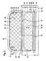
- An in Fig. 1 illustrated first embodiment of a convertible vehicle comprises a vehicle body 10, with a extending in a direction of travel 12 longitudinal direction 14, and arranged in the vehicle body 10 passenger compartment 16, in which at least one row of seats 18 is arranged.
- a generally designated 30 rollover protection device which in the first embodiment comprises two respectively close longitudinal sides 26, 28 of the vehicle body 10 and thus spaced outer racks 32, 34, which project beyond an upper side 36 of the adjoining the rear end 22 of the passenger compartment 16 vehicle body 10 upwards and are connected by a transverse strut 38 with each other.
- the outer stand 34 and the transverse strut 38 enclose a recess 40 of the roll-over protection device 30, which allows the driver in the passenger compartment 16 to look through the roll-over protection device 30 in the direction of a stern 42 of the vehicle body 10.
- the rollover protection device 30 is combined with a wind deflector 50, which obstructs the propagation of the air vortices 46 in the direction of the head region 44 of the occupants.
- This wind deflector 50 includes, as in Fig. 2 shown in detail, a flat material 52, which on the one hand at least partially transparent and on the other hand permeable to air, but is wind-repellent and thus in the in Fig. 2 shown active position, the recess 40 of the roll-over protection device 30 closes wind-preventing and consequently prevents the occupants disturbing air currents due to these properties.
- the flat material 52 is, for example, a pliable flat material, which by a designated as a whole with 60 flat material guiding device in the active position, in Fig. 2 shown pulled, can be brought, in which the flat material 52 closes the recess 40, and on the other hand in an in Fig. 2 Dashed line storage position in the vehicle body 10 below the top 36 can be brought, in which the flat material 52, the recess 40 releases, wherein in the stowed position the flat material 52 is disposed in a stowage receptacle 62 within the vehicle body 10 having an outlet opening 64, from which the Flat material 52 can escape to reach the active position.
- the outlet opening 64 preferably extends between the outer uprights 32 and 34 over the entire width of the recess 40.
- the flat material guiding device 60 in the first embodiment comprises a jig 68, designated as a whole, which has a bracket 68 which is guided in a vertical guide 70 and is movable with this vertical guide 70 between an active position and a stowed position.
- the bracket 68 In the active position of the bracket 68 is located with a cross member 72 on an underside of the cross member 38 and extends with side rails 74 and 76 at least over a subsequent to the cross member 38 portion of the outer stand 32 and 34, wherein the side rails 74 and 76 in Guide rails 78 and 80 of the vertical guide 70 are guided, and wherein the guide rails 78 and 80 hineinerumblen so far in the Verstauage 62, that the entire bracket 68 from the active position, in Fig. 2 shown in full, in a stowage position, in Fig. 2 shown in dashed lines, is movable, in which the entire bracket 68 is arranged in the Verstauage 62 and does not project beyond the outlet opening 64 of the Verstauage.
- the movement of the bracket 68 can be done manually.
- a movement of the bracket 68 by means of a drive 82, which, for example, a drive motor 84 and on the side rails 74 and 76 of the bracket 68 acting, but graphically in Fig. 2 not shown cables comprises, which are driven by the drive motor 84 to move the bracket 68 from the active position to the stowed position and vice versa.
- the flat material 52 is preferably a pliable flat material, it is necessary to retract it into the stowing receiver 62 when the stirrup 68 is moved from the active position to the stowage position.
- a retraction device 90 is provided for this purpose, which is formed in the first embodiment as a winding device with a winding shaft 92 and a winding drive 94, with which the sheet 52 is wound on the winding shaft 92 to a winding 96 and indeed over its entire width between the outer uprights 32 and 34th
- the winding drive 94 may for example be a drive with a spring accumulator, so that the flat material 52 zugbeaufschlagt both in the stowed position of the bracket 68 and in the active position of the bracket 68 through the winding shaft 92 and thus always between the bracket 68 and the winding shaft 92 in Winding 98 is kept taut.
- both the outer stator 32 and 34 and the cross member 38 are formed so that they themselves form a support structure 100 by forming a stable metal tube, said outer stator 32, 34 for partially receiving the side rails 74 and 76 with mutually facing sides of the uprights 32, 34 provided with a longitudinally extending same opening 102, in which the side rails 74 and 76 partially engage, so that held on the side rails 74 and 76 guide body 104 in an inner space 106 of the support structure can run and can be guided in the likewise extending inside the inner space 106 guide rails 78 so that the opening 102 with the interior 106 forms a receptacle for flat material guiding device 60.
- the aperture 102 is provided with elastic lips 112 and 114 held on edges 108, 110 thereof, which in the unbiased state occlude the aperture 102 by abutting each other with their inner ends 116 and 118, while the lips 112 and 114 pass through the lips partially penetrating side rails 74 and 76 can be forced apart to allow the partial entry of the side rails 74 and 76 in the opening 102.
- an opening 102 in the region of the transverse strut 38 is not required, since the bracket 68 can be applied to the transverse strut 72 in the active position on an underside of the transverse strut 38.
- the flat material 52 in a plane F which extends transversely to the vehicle longitudinal direction 14 and the outer stator 32 and 34 and in the first embodiment, the support structure 100 and the outlet opening 64 intersects, so that the flat material web 52 total between a front V and a back R of the stand 32, 34 is located.
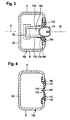
- FIG Fig. 5 In a second embodiment of a convertible vehicle according to the invention, shown in FIG Fig. 5 , those elements which are identical to those of the first embodiment are provided with the same reference numerals, so that with regard to the description of the same can be made in full to the comments on the first embodiment.
- the rollover protection device 30 is not only provided with the outer uprights 32 and 34, but also with inner pillars 122 and 124, which are also spaced apart between the outer uprights 32 and 34.
- the rollover protection means 30 'two Rollover protection elements 130, 132 includes, each of which is arranged, for example behind one of the seats of the seat row 18.
- the rollover protection device 30 'in total in the area of each of the rollover protection elements 130, 132 a of the respective outer stator 32, 34 and the corresponding inner stator 122 and 124 and the respective cross member 126 and 128 enclosed recess 134 and 136 and an intermediate the inner uprights 122, 124 of the rollover protection elements 130, 132 lying recess 138 which is not completed by one of the top 36 of the vehicle body 10 opposite transverse strut.
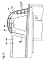
- the flat material 52 in the active position held by the inner posts 122, 124 facing inner sides 142 and 144 of the outer stator 32, 34 in the active position adjacent arms 146, 148 between the outer uprights 32 and 34 taut, the inner stator 122 and 124 thereto are provided with these in the transverse direction 150 between the outer uprights 32, 34 completely penetrating transverse apertures 152, 154 which extend from the outlet opening 64 in the top 36 of the vehicle body 10 to the crossbars 126, 128, thereby totaling the inner Carrier 122 and 124 in two parts extending from the outlet opening 64 to the cross braces 126, 128 and thus in this embodiment, the sheet 52 is in the active position in the surface F, which extends transversely to the vehicle longitudinal direction 14 and the outer stator 32 and 34 and in this embodiment, even the inner stator 122 and 124 beautiful Eidet.
- the arms 146 and 148 are formed so that their upper ends 156, 158 in the active position hold the sheet 52 so taut that an upper edge 160 of the sheet 52 extends substantially straight between the uprights 32 and 34.
- the arms 146 and 148 are pivotally mounted about approximately parallel to the vehicle longitudinal direction 14 extending pivot axes 162 and 164, in such a way that the ends 156, 158 are movable in the direction of the outlet opening 64 and hin manbewegbar therethrough to the in Fig. 9 Stowed position shown in dashed lines of the arms 146, 148 reach, in which these no longer survive through the outlet opening 64, but lie within the Verstaury 62.
- the flat material 52 held on the arms 146 and 148 is also moved into the stowing receiver 62 through the outlet opening 64 and wound into a reel 96 by a retraction device 90 provided, for example, as a retractor, for example in the stowage receiver 62. as described in connection with the first embodiment.
- a retraction device 90 provided, for example, as a retractor, for example in the stowage receiver 62. as described in connection with the first embodiment.
- the outlet opening 64 has a width such that the arms 146, 148 are movable therethrough, wherein the outlet opening 64 is closed, for example by elastic lips.
- the arms 146 and 148 are preferably provided with gear segments 166 and 168 arranged in the region of the stowage receiver 62, which together with the arms 146 and 148 extend around the arms Pivot axes 162 and 164 are pivotable and in each case for example with drive screws 170 and 172 are in engagement, the drive screws 170 and 172 are driven by drive units 174 and 176, which are either individual electric motors or coupled together by a drive motor driven to the arms 146th 148 between the active position and the stowage and vice versa back and forth.
- drive units 174 and 176 which are either individual electric motors or coupled together by a drive motor driven to the arms 146th 148 between the active position and the stowage and vice versa back and forth.
- FIG Fig. 10 and 11 corresponds in principle to the second embodiment, with the difference that the flat material 52 is held in the region of the upper edge 160 by a end rail 180 which extends in the transverse direction 150 between the outer uprights 132 and 134 and on which the arms 146, 148 with their ends 156, 158 attack, wherein the ends 156 and 158 in provided on the end rail 180 guides 182, 184 along the end rail 180 are movable.
- Pivoting the arms 146 and 148 now causes the entire end rail 180 to move toward the exit opening 64 with the ends 156, 158 of the arms 146 and 148 in the guides 182 and 184 moving and converging. As a result, the end rail 180 can be aligned substantially parallel to the outlet opening 64 to move to this.
- the end rail 180 is provided on its side facing away from the vehicle body 10 with a cover 186, with which in the stowed position of the arms 146, 148, the outlet opening 64 can be covered.
- the transverse openings 152 and 154 of the inner stand 122 and 124 are designed such that the end rail 180 together with the cover 186 and guided on the end rail 180 arms 146, 148 can move through the transverse openings 152, 154.
- the arms 146 and 148 can be driven to pivot about the pivot axes 162 and 164 in the same manner as in the second embodiment.
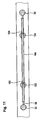
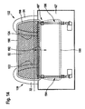
- the flat material 52 as shown schematically in FIG Fig. 14 shown held clamped in a rigid frame 190 which surrounds the sheet 52 on one side and undeformed between the in Fig. 14 shown active position in the in Fig. 14 Dashboard shown stowed and vice versa is movable.
- the frame 190 is part of the movement of the flat material 52 permitting sheet guiding device 60, which in addition to the frame 190 still this in a direction of displacement 192 moving linear actuators 194, 196 includes, as described for example in the German patent application DE 199 02 242 A1 are described.
- the frame 190 may, as in Fig. 14 represented merely by an outer frame 198 may be formed, which surrounds the sheet 52 on the outside.
- the frame 190 has a plurality of openings, for example, a central opening 200 and outer openings 202, which arise from the fact that the outer frame 198 is additionally divided by intermediate webs 204.
- the outer openings 202 are arranged so that they lie in the region of the recesses 134 and 136 of the rollover protection elements 130 and 132 and the central opening 200 is arranged so that it lies in the region of the recess 138 between the rollover protection elements 130 and 132.
- the frame 190 ' is preferably formed by two plates 210 and 212, between which the sheet 52 is clamped so that it overlaps the openings 200 and 202 of the frame 190'.
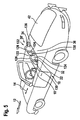
- the rollover protection elements 130 and 132 exemplified by the example of the rollover protection element 130, formed so that an outer contour of the stator 32, 34, 122 and 124 and the crossbars 126 and 128 is not determined by the support structure.
- each of the transverse opening 152 is formed, so that the housing sections 222, 224 are not connected to each other in the region of the inner stator 122, 124, but each adjacent to the transverse opening 152.
- the support structure 100 ' extends separately from the stator housing 220 in the interior 106' thereof and is completely independent of the stator housing 220, which in turn does not contribute to the stability of the support structure 100 '.
- the support structure 100 ' is formed by a, in the interior 106' of the stand 32, 34, 122, 124 extending and also the transverse struts 126 and 128 extending inverted U-shaped tubular bracket 228.
- stator housing 220 integrally into a corresponding cross member housing 230, and the interior 106 'is continued from the stator housing 220 in the cross member housing 230, so that the inverted U-shaped tubular bracket 228 can run as a contiguous part in the interior 106' wherein the cross member housing 230 integrally connected to the stator housings 220 is also formed by a front housing portion 232 and a rear housing portion 234, both of which are integrally formed with the corresponding housing portions 222, 224 of the stator housing 220.
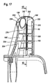
- a flexible cover strip 240 in an outer contour of the housing sections 222 and 232 and 224 and 234 extending guides 242 is slidably guided, wherein the guides 242 on an interior 106 'facing the inside extend between the housing sections 222, 232 and 224, 234 in the region of the outer stand 32, 34 and the cross struts 126, 128 provided connecting element 226, so that the cover strip 240 in the active position of the sheet 52 on the inside of the connecting element 226 in the interior 106 ' lies and in the stowed position of the flat material 52, the transverse openings 152, 154 in the region of mutually facing sides 244 of the inner stator 122, 124 closes.
- the cover strip 240 is provided at its end facing the frame 190 'with a bearing head 246, in which an actuating rod 248 engages, which in turn acts on the intermediate web 204 of the frame 190', and in a region facing away from the guide head 246, wherein the guide rod 248 thus in the interior 106 'of the stator housing 220 of the inner stator 122, 124 extends.
- the flexible cover strip 240 is pushed over the guides 242 on the inside of the connecting element 226 in the interior 106' of the cross-strut housing 230 and the stator housing 220 of the outer stator 32 and the frame 190 'may move into the corresponding transverse opening 152, 154.
- the actuating rod 248 pulls on the bearing head 246 of the flexible cover strip 240 and pulls it in the guides 242 in the direction of the outlet opening 64, thereby causing the transverse opening 152, 154 at the respective Inside 244 of the corresponding inner stator 122, 124 is closed.
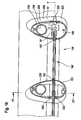
- the frame 190 is formed so that it has a total of three sub-frames, namely the sub-frames 254 and 256, which are movable into the recesses 134 and 136, to close this wind-preventing, and the sub-frame 258, which is intended to close the recess 138 between the rollover protection elements 130 and 132.
- the sub-frames 254, 256 and 258 are seated on a common carrier 260, which is movable by linear drives 194 and 196, as described for example in the fourth embodiment, to the entire frame 190 "of the in Fig. 19 shown active position in the in Fig. 20 shown stowed position and vice versa.
- Each of these sub-frames 254, 256, 258 clamps a flat piece of material 52 provided for this subframe, which is formed in the same way as in the embodiments described above.
- the sixth embodiment is preferably formed so that the outer stator 32, 34 and the inner stator 122, 124 are provided with receptacles for the flat material guide device 60, for example, with leading into the respective interior openings 102, which serve to the sub-frame 254th , 256 and 258 in the active position relative to the uprights 32, 34, 122, 124 to guide and hold in position.
- the inner stator 122, 124 are provided with transverse openings. Rather, it is sufficient to provide each of the recesses 134, 136 and 138 facing arranged apertures 102, but not enforce the inner stator 122 and 124 completely in the transverse direction.
Landscapes
- Engineering & Computer Science (AREA)
- Mechanical Engineering (AREA)
- Body Structure For Vehicles (AREA)
- Vehicle Step Arrangements And Article Storage (AREA)
- Fittings On The Vehicle Exterior For Carrying Loads, And Devices For Holding Or Mounting Articles (AREA)
Claims (38)
- Véhicule convertible comprenant une carrosserie de véhicule (10) avec un habitacle (16), au moins une rangée de sièges (18) disposée dans l'habitacle (16), un dispositif de protection contre le retournement (30) disposé derrière ladite au moins une rangée de sièges (16) et présentant une découpe (40, 134, 136, 138) tournée vers l'arrière (42) de la carrosserie de véhicule (10) avec au moins deux montants (32, 34, 122, 124) disposés à distance l'un de l'autre transversalement à une direction longitudinale (14) de la carrosserie de véhicule (10) et s'élevant au-dessus de la carrosserie de véhicule (10) et avec au moins une entretoise transversale (38, 126, 128) s'étendant entre lesdits au moins deux montants (32, 34, 122, 124), et un dispositif pare-vent (50) disposé derrière ladite au moins une rangée de sièges (18), qui réduit un courant d'air à travers ladite au moins une découpe (40, 134, 136, 138) du dispositif de protection contre le retournement (30), et qui présente un dispositif de guidage de matériau plat (60) et un matériau plat (52) déviant le vent maintenu par le dispositif de guidage de matériau plat (60), caractérisé en ce que le dispositif de guidage de matériau plat (60) maintient le matériau plat (52) déviant le vent dans une position active dans un plan (F) coupant les montants (32, 34, 122, 124) et ferme de ce fait ladite au moins une découpe (40, 134, 136, 138) en arrêtant le vent, et en ce que le matériau plat (52) déviant le vent peut être amené, au moyen du dispositif de guidage de matériau plat (60), de la position active dans une position de rangement située dans la carrosserie de véhicule (10), dans laquelle le matériau plat (52) déviant le vent libère la découpe (40, 134, 136, 138), et inversement.
- Véhicule convertible selon la revendication 1, caractérisé en ce que le dispositif de guidage de matériau plat (60) est pourvu d'un entraînement (82, 174, 176, 194, 196), afin de déplacer le matériau plat (52) déviant le vent entre la position active et la position de rangement et inversement.
- Véhicule convertible selon la revendication 1 ou 2, caractérisé en ce qu'il est prévu dans la carrosserie de véhicule (10) un logement de rangement (62) disposé à proximité du dispositif de protection contre le retournement (30) pour le logement du matériau plat (52) déviant le vent dans la position de rangement.
- Véhicule convertible selon la revendication 3, caractérisé en ce que le logement de rangement (62) présente une ouverture de sortie (64) tournée vers le dispositif de protection contre le retournement (30) pour le matériau plat (52) déviant le vent.
- Véhicule convertible selon la revendication 4, caractérisé en ce que le plan (F), dans lequel s'étend le matériau plat (52) déviant le vent dans la position active, traverse l'ouverture de sortie (64).
- Véhicule convertible selon la revendication 4 ou 5, caractérisé en ce que le dispositif de guidage de matériau plat (60) comprend un élément de fermeture (186) pour l'ouverture de sortie (64).
- Véhicule convertible selon l'une quelconque des revendications précédentes, caractérisé en ce que le matériau plat (52) déviant le vent est rigide à la flexion.
- Véhicule convertible selon la revendication 7, caractérisé en ce que le dispositif de guidage de matériau plat (60) comprend un dispositif de tension (66), avec lequel le matériau plat (52) déviant le vent peut être tendu au-dessus de la découpe (40, 134, 136, 138) dans la position active.
- Véhicule convertible selon la revendication 8, caractérisé en ce que le dispositif de tension (66) comprend un arceau (68) mobile dans un guide (70) et maintenant le matériau plat (52) déviant le vent sous tension dans une direction transversale.
- Véhicule convertible selon la revendication 9, caractérisé en ce que le dispositif de tension (66') présente deux bras (146, 148) pouvant pivoter entre une position active et une position de rangement, qui maintiennent le matériau plat (52) déviant le vent sous tension dans la direction transversale.
- Véhicule convertible selon la revendication 10, caractérisé en ce que les bras (146, 148) sont disposés de manière pivotante à proximité des montants (32, 34) limitant côté extérieur ladite au moins une découpe respective (40, 134, 136, 138) et s'étendent à peu près parallèlement à ceux-ci dans la position active.
- Véhicule convertible selon la revendication 10 ou 11, caractérisé en ce que les bras (146, 148) s'étendent transversalement aux montants (32, 34) dans la position de rangement.
- Véhicule convertible selon l'une quelconque des revendications 8 à 12, caractérisé en ce que le dispositif de guidage de matériau plat (60) comprend un dispositif de rentrage (90) disposé dans la carrosserie de véhicule (10) pour déplacer le matériau plat (52) déviant le vent dans la position de rangement.
- Véhicule convertible selon la revendication 13, caractérisé en ce que le dispositif de rentrage (90) comprend un dispositif d'enroulement (92, 94) pour le matériau plat (52) déviant le vent.
- Véhicule convertible selon l'une quelconque des revendications 1 à 8, caractérisé en ce que le dispositif de guidage de matériau plat (60) comprend un cadre (190) contenant le matériau plat (52) déviant le vent et un dispositif de déplacement (194, 196) pour le mouvement du cadre entre une position de rangement et une position active.
- Véhicule convertible selon la revendication 15, caractérisé en ce que le cadre (190) est disposé en position abaissée par le dispositif de déplacement (194, 196) dans la position de rangement dans la carrosserie de véhicule (10).
- Véhicule convertible selon la revendication 16, caractérisé en ce que dans la position de rangement le cadre (190) est situé dans un plan (F) s'étendant transversalement à la direction longitudinale (14) de la carrosserie de véhicule (10).
- Véhicule convertible selon l'une quelconque des revendications 15 à 17, caractérisé en ce que le dispositif de guidage de matériau plat (60) présente un cadre (190, 190') d'une seule pièce pour maintenir le matériau plat (52).
- Véhicule convertible selon la revendication 18, caractérisé en ce que le cadre (190, 190'), dans la position active du dispositif de guidage de matériau plat (60), positionne le matériau plat (52) dans toutes les découpes (40, 134, 136, 138) en arrêtant le vent.
- Véhicule convertible selon l'une quelconque des revendications 15 à 17, caractérisé en ce que le dispositif de guidage de matériau plat (60) présente un cadre (190") en plusieurs parties.
- Véhicule convertible selon la revendication 20, caractérisé en ce que le cadre en plusieurs parties (190") comprend plusieurs cadres partiels (254, 256, 258) maintenus par un support commun (260).
- Véhicule convertible selon l'une quelconque des revendications précédentes, caractérisé en ce que le dispositif de protection contre le retournement (30) comprend deux montants extérieurs (32, 34) respectivement disposés en position tournée vers les côtés longitudinaux de la carrosserie de véhicule (10) et reliés par l'entretoise transversale (38).
- Véhicule convertible selon la revendication 22, caractérisé en ce que le dispositif de protection contre le retournement (30) présente une découpe (40) encadrée par les montants extérieurs (32, 34) et l'entretoise transversale (38).
- Véhicule convertible selon l'une quelconque des revendications 1 à 21, caractérisé en ce que le dispositif de protection contre le retournement (30') comprend deux éléments de protection contre le retournement (130, 132), dont chacun comprend deux montants (32, 122, 34, 124) et une entretoise transversale (126, 128).
- Véhicule convertible selon la revendication 24, caractérisé en ce que chacun des éléments de protection contre le retournement (130, 132) présente un montant extérieur (32, 34), disposé en position tournée vers le côté longitudinal respectif de la carrosserie de véhicule (10), et un montant intérieur (122, 124).
- Véhicule convertible selon la revendication 24 ou 25, caractérisé en ce qu'une (138) des découpes (134, 136, 138) du dispositif de protection contre le retournement (30') est située entre les éléments de protection contre le retournement (130, 132).
- Véhicule convertible selon l'une quelconque des revendications 24 à 26, caractérisé en ce que chacun des éléments de protection contre le retournement (130, 132) présente une autre découpe (134, 136) encadrée par les montants (32, 122, 34, 124) et les entretoises transversales (126, 128).
- Véhicule convertible selon l'une quelconque des revendications précédentes, caractérisé en ce qu'au moins deux des montants (32, 34, 122, 124) présentent au moins un logement (102, 106, 152, 154) pour le dispositif de guidage de matériau plat (60).
- Véhicule convertible selon la revendication 28, caractérisé en ce que les montants extérieurs présentent chacun un logement (102, 106).
- Véhicule convertible selon la revendication 28 ou 29, caractérisé en ce qu'au moins un montant intérieur (122, 124) présente au moins un logement (102).
- Véhicule convertible selon l'une quelconque des revendications 28 à 30, caractérisé en ce qu'au moins un des montants intérieurs (122, 124) est traversé par le matériau plat (52) déviant le vent se trouvant dans la position active.
- Véhicule convertible selon la revendication 31, caractérisé en ce que les montants intérieurs sont pourvus de passages transversaux (152, 154), qui sont traversés par le matériau plat (52) déviant le vent se trouvant dans la position active.
- Véhicule convertible selon l'une quelconque des revendications précédentes, caractérisé en ce que les montants (32, 34, 122, 124) présentent un boîtier extérieur formant une structure de support (100).
- Véhicule convertible selon l'une quelconque des revendications précédentes, caractérisé en ce que les entretoises transversales (38, 126, 128) présentent un boîtier extérieur formant la structure de support (100).
- Véhicule convertible selon l'une quelconque des revendications 1 à 32, caractérisé en ce que les montants (32, 34) présentent un boîtier de montant (220) et une structure de support (228) s'étendant dans le boîtier de montant.
- Véhicule convertible selon l'une quelconque des revendications 1 à 33, caractérisé en ce que ladite au moins une entretoise transversale présente un boîtier d'entretoise transversale (230) et une structure de support (228) s'étendant dans le boîtier d'entretoise transversale.
- Véhicule convertible selon la revendication 35 ou 36, caractérisé en ce que la structure de support (228) est disposée sur un côté du plan (F), dans lequel le matériau plat (52) déviant le vent s'étend dans la position active.
- Véhicule convertible selon la revendication 37, caractérisé en ce que la structure de support (228) de l'entretoise transversale (126, 128) est disposée sur le même côté du plan (F) que la structure de support (228) des montants (32, 34, 122, 124).
Applications Claiming Priority (2)
| Application Number | Priority Date | Filing Date | Title |
|---|---|---|---|
| DE10341989A DE10341989A1 (de) | 2003-09-09 | 2003-09-09 | Cabriofahrzeug |
| DE10341989 | 2003-09-09 |
Publications (2)
| Publication Number | Publication Date |
|---|---|
| EP1514714A1 EP1514714A1 (fr) | 2005-03-16 |
| EP1514714B1 true EP1514714B1 (fr) | 2012-03-28 |
Family
ID=34129757
Family Applications (1)
| Application Number | Title | Priority Date | Filing Date |
|---|---|---|---|
| EP04021175A Expired - Lifetime EP1514714B1 (fr) | 2003-09-09 | 2004-09-07 | Véhicule convertible |
Country Status (4)
| Country | Link |
|---|---|
| US (1) | US7198321B2 (fr) |
| EP (1) | EP1514714B1 (fr) |
| AT (1) | ATE551218T1 (fr) |
| DE (1) | DE10341989A1 (fr) |
Families Citing this family (14)
| Publication number | Priority date | Publication date | Assignee | Title |
|---|---|---|---|---|
| DE102005029696A1 (de) * | 2005-06-24 | 2006-12-28 | Wilhelm Karmann Gmbh | Windschott für ein Cabriolet-Fahrzeug |
| FR2892073B1 (fr) * | 2005-10-19 | 2009-07-03 | Heuliez Sa | Dispositif a filet anti-remous |
| DE102006029135A1 (de) * | 2006-06-22 | 2008-01-03 | iKON GbR Körber & Ortel (vertretungsberechtigte Gesellschafter Stefan Körber, 85092 Kösching und Andreas Ortel, 92334 Berching) | Schott für ein Personenkraftfahrzeug, Steckverbinder für ein Schott und Verfahren zur Herstellung eines Schotts |
| DE102006039950A1 (de) * | 2006-08-25 | 2008-02-28 | Dr.Ing.H.C. F. Porsche Ag | Cabriolet mit zwei voneinander beabstandete Überrollbügeln und einem Windschott |
| DE102006052096A1 (de) * | 2006-11-04 | 2008-05-08 | Dr.Ing.H.C. F. Porsche Ag | Windschott und Cabriolet mit einem solchen Windschott |
| US20080106121A1 (en) * | 2006-11-06 | 2008-05-08 | Douglas Ryan Lissner | Wind shield with metallic mesh |
| DE102007019237A1 (de) | 2007-04-24 | 2008-10-30 | Daimler Ag | Windschott |
| DE202007012387U1 (de) * | 2007-08-31 | 2009-01-02 | Brose Fahrzeugteile Gmbh & Co. Kommanditgesellschaft, Hallstadt | Schottmechanismus für ein Kraftfahrzeug |
| DE102008016908A1 (de) * | 2008-03-25 | 2009-10-01 | Scambia Industrial Developments Aktiengesellschaft | Windstoppeinrichtung |
| DE102008046549B4 (de) * | 2008-09-10 | 2020-10-08 | Dr. Ing. H.C. F. Porsche Aktiengesellschaft | Tragstruktur in einem Kraftfahrzeug |
| DE102009035335A1 (de) * | 2009-07-21 | 2011-01-27 | Scambia Industrial Developments Aktiengesellschaft | Antriebseinheit für eine Windstopeinrichtung |
| DE102009037824A1 (de) | 2009-08-10 | 2011-02-17 | Bos Gmbh & Co. Kg | Rollosystem für ein Kraftfahrzeug |
| DE102010056233B4 (de) * | 2010-12-24 | 2017-11-09 | Audi Ag | Rollo-Windschott für ein Cabrio-Fahrzeug |
| DE102012105173B4 (de) | 2012-06-14 | 2021-09-30 | Dr. Ing. H.C. F. Porsche Aktiengesellschaft | Windschott |
Family Cites Families (11)
| Publication number | Priority date | Publication date | Assignee | Title |
|---|---|---|---|---|
| DE4119529A1 (de) * | 1991-06-13 | 1992-12-17 | Bayerische Motoren Werke Ag | Cabriolet mit einem windschutz |
| DE19632352B4 (de) * | 1995-09-09 | 2004-08-05 | Dr.Ing.H.C. F. Porsche Ag | Windschott für ein Cabriolet |
| DE19534584C1 (de) * | 1995-09-09 | 1996-09-12 | Porsche Ag | Windschott für ein Cabriolet |
| DE19536552C2 (de) * | 1995-09-29 | 2000-05-25 | Daimler Chrysler Ag | Windschott für ein Cabriolet mit mindestens einem Überrollbügel |
| DE19602598C1 (de) * | 1996-01-25 | 1997-03-06 | Daimler Benz Ag | Offener Personenkraftwagen |
| DE19752068B4 (de) * | 1997-11-25 | 2008-12-24 | Dr. Ing. H.C. F. Porsche Aktiengesellschaft | Dachaufbau für Fahrzeuge |
| DE19826672A1 (de) | 1998-06-16 | 1999-12-23 | Bayerische Motoren Werke Ag | Überrollschutz-System für ein Kraftfahrzeug, insbesondere für ein Cabriolet |
| DE10035995A1 (de) * | 2000-07-25 | 2002-02-21 | Oris Fahrzeugteile Riehle H | Windschott |
| DE10050284A1 (de) * | 2000-10-10 | 2002-04-25 | Cts Fahrzeug Dachsysteme Gmbh | Windschott für ein Cabriolet-Fahrzeug |
| DE10061562A1 (de) * | 2000-12-04 | 2002-06-13 | Oris Fahrzeugteile Riehle H | Windschott |
| DE10131397B4 (de) * | 2001-06-28 | 2005-02-24 | Daimlerchrysler Ag | Windschott für ein Kraftfahrzeug |
-
2003
- 2003-09-09 DE DE10341989A patent/DE10341989A1/de not_active Ceased
-
2004
- 2004-09-07 EP EP04021175A patent/EP1514714B1/fr not_active Expired - Lifetime
- 2004-09-07 AT AT04021175T patent/ATE551218T1/de active
- 2004-09-08 US US10/937,114 patent/US7198321B2/en not_active Expired - Lifetime
Also Published As
| Publication number | Publication date |
|---|---|
| DE10341989A1 (de) | 2005-04-21 |
| EP1514714A1 (fr) | 2005-03-16 |
| US20050057072A1 (en) | 2005-03-17 |
| ATE551218T1 (de) | 2012-04-15 |
| US7198321B2 (en) | 2007-04-03 |
Similar Documents
| Publication | Publication Date | Title |
|---|---|---|
| EP1514714B1 (fr) | Véhicule convertible | |
| EP1479564A2 (fr) | dispositif de protection pour intérieur véhicule | |
| DE10063770B4 (de) | Windschutzvorrichtung für ein Kraftfahrzeug | |
| DE10005951A1 (de) | Heckfensterrollo | |
| DE102016009136B4 (de) | Kraftwagen mit einem Dachmodul | |
| DE102008006157A1 (de) | Windschottanordnung | |
| DE10218701C1 (de) | Überrollbügelanordnung für ein Kraftfahrzeug | |
| EP0718135B1 (fr) | Revêtement déflecteur de vent pour véhicules conversibles | |
| DE102012101752B4 (de) | Kraftfahrzeug mit einer Dachöffnung | |
| DE4345425C2 (de) | Überrollschutz-Vorrichtung für ein Kraftfahrzeug | |
| DE2308080C2 (de) | Starres Schiebehebedach, insbesondere für Kraftfahrzeuge | |
| DE102015218200B3 (de) | Windschutzvorrichtung an einem verschließbaren Dachausschnitt eines Kraftfahrzeugs | |
| DE102004055404A1 (de) | Fahrzeugdach | |
| EP1588881B1 (fr) | Véhicule avec des parties de toit mobiles | |
| DE102011018288A1 (de) | Windabweiserbaugruppe sowie Bügeleinheit eines Windabweisers | |
| DE102006008653A1 (de) | Windstoppeinrichtung für ein Cabrioletfahrzeug | |
| EP1736342B1 (fr) | Déflecteur de vent pour un cabriolet et cabriolet avec un déflecteur de vent | |
| DE102009043248B3 (de) | Führungsanordnung für ein bewegbares Dachteil eines Fahrzeugdachs | |
| EP2596972B1 (fr) | Dispositif de protection contre le vent | |
| DE102004063466B4 (de) | Fahrzeugdachanordnung mit einem Deckel und einem Schiebehimmel | |
| DE10203677A1 (de) | Träger für Dachlastenträger für Fahrzeuge | |
| DE10231169B4 (de) | Fahrzeugdach | |
| DE102006037454A1 (de) | Cabriolet-Fahrzeug mit einem Gepäckraum und einer Trennwand zum Abtrennen eines Verdeckaufnahmebereiches | |
| DE102023206174A1 (de) | Dach eines Fahrzeugs | |
| DE102006058106A1 (de) | Windschott für ein Cabrioletfahrzeug |
Legal Events
| Date | Code | Title | Description |
|---|---|---|---|
| PUAI | Public reference made under article 153(3) epc to a published international application that has entered the european phase |
Free format text: ORIGINAL CODE: 0009012 |
|
| AK | Designated contracting states |
Kind code of ref document: A1 Designated state(s): AT BE BG CH CY CZ DE DK EE ES FI FR GB GR HU IE IT LI LU MC NL PL PT RO SE SI SK TR |
|
| AX | Request for extension of the european patent |
Extension state: AL HR LT LV MK |
|
| 17P | Request for examination filed |
Effective date: 20050616 |
|
| AKX | Designation fees paid |
Designated state(s): AT BE BG CH CY CZ DE DK EE ES FI FR GB GR HU IE IT LI LU MC NL PL PT RO SE SI SK TR |
|
| RAP1 | Party data changed (applicant data changed or rights of an application transferred) |
Owner name: SCAMBIA INDUSTRIAL DEVELOPMENTS AKTIENGESELLSCHAFT |
|
| 17Q | First examination report despatched |
Effective date: 20071115 |
|
| GRAP | Despatch of communication of intention to grant a patent |
Free format text: ORIGINAL CODE: EPIDOSNIGR1 |
|
| GRAS | Grant fee paid |
Free format text: ORIGINAL CODE: EPIDOSNIGR3 |
|
| GRAA | (expected) grant |
Free format text: ORIGINAL CODE: 0009210 |
|
| AK | Designated contracting states |
Kind code of ref document: B1 Designated state(s): AT BE BG CH CY CZ DE DK EE ES FI FR GB GR HU IE IT LI LU MC NL PL PT RO SE SI SK TR |
|
| REG | Reference to a national code |
Ref country code: GB Ref legal event code: FG4D Free format text: NOT ENGLISH |
|
| REG | Reference to a national code |
Ref country code: CH Ref legal event code: EP |
|
| REG | Reference to a national code |
Ref country code: AT Ref legal event code: REF Ref document number: 551218 Country of ref document: AT Kind code of ref document: T Effective date: 20120415 |
|
| REG | Reference to a national code |
Ref country code: IE Ref legal event code: FG4D Free format text: LANGUAGE OF EP DOCUMENT: GERMAN |
|
| REG | Reference to a national code |
Ref country code: DE Ref legal event code: R096 Ref document number: 502004013396 Country of ref document: DE Effective date: 20120524 |
|
| REG | Reference to a national code |
Ref country code: NL Ref legal event code: VDEP Effective date: 20120328 |
|
| PG25 | Lapsed in a contracting state [announced via postgrant information from national office to epo] |
Ref country code: FI Free format text: LAPSE BECAUSE OF FAILURE TO SUBMIT A TRANSLATION OF THE DESCRIPTION OR TO PAY THE FEE WITHIN THE PRESCRIBED TIME-LIMIT Effective date: 20120328 Ref country code: GR Free format text: LAPSE BECAUSE OF FAILURE TO SUBMIT A TRANSLATION OF THE DESCRIPTION OR TO PAY THE FEE WITHIN THE PRESCRIBED TIME-LIMIT Effective date: 20120629 |
|
| PG25 | Lapsed in a contracting state [announced via postgrant information from national office to epo] |
Ref country code: CY Free format text: LAPSE BECAUSE OF FAILURE TO SUBMIT A TRANSLATION OF THE DESCRIPTION OR TO PAY THE FEE WITHIN THE PRESCRIBED TIME-LIMIT Effective date: 20120328 |
|
| PG25 | Lapsed in a contracting state [announced via postgrant information from national office to epo] |
Ref country code: EE Free format text: LAPSE BECAUSE OF FAILURE TO SUBMIT A TRANSLATION OF THE DESCRIPTION OR TO PAY THE FEE WITHIN THE PRESCRIBED TIME-LIMIT Effective date: 20120328 Ref country code: RO Free format text: LAPSE BECAUSE OF FAILURE TO SUBMIT A TRANSLATION OF THE DESCRIPTION OR TO PAY THE FEE WITHIN THE PRESCRIBED TIME-LIMIT Effective date: 20120328 Ref country code: CZ Free format text: LAPSE BECAUSE OF FAILURE TO SUBMIT A TRANSLATION OF THE DESCRIPTION OR TO PAY THE FEE WITHIN THE PRESCRIBED TIME-LIMIT Effective date: 20120328 Ref country code: SE Free format text: LAPSE BECAUSE OF FAILURE TO SUBMIT A TRANSLATION OF THE DESCRIPTION OR TO PAY THE FEE WITHIN THE PRESCRIBED TIME-LIMIT Effective date: 20120328 Ref country code: PL Free format text: LAPSE BECAUSE OF FAILURE TO SUBMIT A TRANSLATION OF THE DESCRIPTION OR TO PAY THE FEE WITHIN THE PRESCRIBED TIME-LIMIT Effective date: 20120328 Ref country code: SI Free format text: LAPSE BECAUSE OF FAILURE TO SUBMIT A TRANSLATION OF THE DESCRIPTION OR TO PAY THE FEE WITHIN THE PRESCRIBED TIME-LIMIT Effective date: 20120328 |
|
| PG25 | Lapsed in a contracting state [announced via postgrant information from national office to epo] |
Ref country code: PT Free format text: LAPSE BECAUSE OF FAILURE TO SUBMIT A TRANSLATION OF THE DESCRIPTION OR TO PAY THE FEE WITHIN THE PRESCRIBED TIME-LIMIT Effective date: 20120730 Ref country code: SK Free format text: LAPSE BECAUSE OF FAILURE TO SUBMIT A TRANSLATION OF THE DESCRIPTION OR TO PAY THE FEE WITHIN THE PRESCRIBED TIME-LIMIT Effective date: 20120328 |
|
| PG25 | Lapsed in a contracting state [announced via postgrant information from national office to epo] |
Ref country code: DK Free format text: LAPSE BECAUSE OF FAILURE TO SUBMIT A TRANSLATION OF THE DESCRIPTION OR TO PAY THE FEE WITHIN THE PRESCRIBED TIME-LIMIT Effective date: 20120328 Ref country code: NL Free format text: LAPSE BECAUSE OF FAILURE TO SUBMIT A TRANSLATION OF THE DESCRIPTION OR TO PAY THE FEE WITHIN THE PRESCRIBED TIME-LIMIT Effective date: 20120328 |
|
| PLBE | No opposition filed within time limit |
Free format text: ORIGINAL CODE: 0009261 |
|
| STAA | Information on the status of an ep patent application or granted ep patent |
Free format text: STATUS: NO OPPOSITION FILED WITHIN TIME LIMIT |
|
| PG25 | Lapsed in a contracting state [announced via postgrant information from national office to epo] |
Ref country code: IT Free format text: LAPSE BECAUSE OF FAILURE TO SUBMIT A TRANSLATION OF THE DESCRIPTION OR TO PAY THE FEE WITHIN THE PRESCRIBED TIME-LIMIT Effective date: 20120328 |
|
| 26N | No opposition filed |
Effective date: 20130103 |
|
| BERE | Be: lapsed |
Owner name: SCAMBIA INDUSTRIAL DEVELOPMENTS AKTIENGESELLSCHAFT Effective date: 20120930 |
|
| REG | Reference to a national code |
Ref country code: DE Ref legal event code: R097 Ref document number: 502004013396 Country of ref document: DE Effective date: 20130103 |
|
| PG25 | Lapsed in a contracting state [announced via postgrant information from national office to epo] |
Ref country code: ES Free format text: LAPSE BECAUSE OF FAILURE TO SUBMIT A TRANSLATION OF THE DESCRIPTION OR TO PAY THE FEE WITHIN THE PRESCRIBED TIME-LIMIT Effective date: 20120709 Ref country code: MC Free format text: LAPSE BECAUSE OF NON-PAYMENT OF DUE FEES Effective date: 20120930 |
|
| REG | Reference to a national code |
Ref country code: CH Ref legal event code: PL |
|
| GBPC | Gb: european patent ceased through non-payment of renewal fee |
Effective date: 20120907 |
|
| REG | Reference to a national code |
Ref country code: IE Ref legal event code: MM4A |
|
| PG25 | Lapsed in a contracting state [announced via postgrant information from national office to epo] |
Ref country code: LI Free format text: LAPSE BECAUSE OF NON-PAYMENT OF DUE FEES Effective date: 20120930 Ref country code: IE Free format text: LAPSE BECAUSE OF NON-PAYMENT OF DUE FEES Effective date: 20120907 Ref country code: CH Free format text: LAPSE BECAUSE OF NON-PAYMENT OF DUE FEES Effective date: 20120930 Ref country code: BE Free format text: LAPSE BECAUSE OF NON-PAYMENT OF DUE FEES Effective date: 20120930 Ref country code: BG Free format text: LAPSE BECAUSE OF FAILURE TO SUBMIT A TRANSLATION OF THE DESCRIPTION OR TO PAY THE FEE WITHIN THE PRESCRIBED TIME-LIMIT Effective date: 20120628 Ref country code: GB Free format text: LAPSE BECAUSE OF NON-PAYMENT OF DUE FEES Effective date: 20120907 |
|
| REG | Reference to a national code |
Ref country code: AT Ref legal event code: MM01 Ref document number: 551218 Country of ref document: AT Kind code of ref document: T Effective date: 20120907 |
|
| PG25 | Lapsed in a contracting state [announced via postgrant information from national office to epo] |
Ref country code: AT Free format text: LAPSE BECAUSE OF NON-PAYMENT OF DUE FEES Effective date: 20120907 |
|
| PG25 | Lapsed in a contracting state [announced via postgrant information from national office to epo] |
Ref country code: TR Free format text: LAPSE BECAUSE OF FAILURE TO SUBMIT A TRANSLATION OF THE DESCRIPTION OR TO PAY THE FEE WITHIN THE PRESCRIBED TIME-LIMIT Effective date: 20120328 |
|
| PG25 | Lapsed in a contracting state [announced via postgrant information from national office to epo] |
Ref country code: LU Free format text: LAPSE BECAUSE OF NON-PAYMENT OF DUE FEES Effective date: 20120907 |
|
| PG25 | Lapsed in a contracting state [announced via postgrant information from national office to epo] |
Ref country code: HU Free format text: LAPSE BECAUSE OF FAILURE TO SUBMIT A TRANSLATION OF THE DESCRIPTION OR TO PAY THE FEE WITHIN THE PRESCRIBED TIME-LIMIT Effective date: 20040907 |
|
| REG | Reference to a national code |
Ref country code: FR Ref legal event code: TP Owner name: SCAMBIA HOLDINGS CYPRUS LIMITED, CY Effective date: 20150105 |
|
| REG | Reference to a national code |
Ref country code: DE Ref legal event code: R082 Ref document number: 502004013396 Country of ref document: DE Representative=s name: HOEGER, STELLRECHT & PARTNER PATENTANWAELTE, DE |
|
| REG | Reference to a national code |
Ref country code: DE Ref legal event code: R081 Ref document number: 502004013396 Country of ref document: DE Owner name: SCAMBIA HOLDINGS CYPRUS LTD., CY Free format text: FORMER OWNER: ORIS FAHRZEUGTEILE HANS RIEHLE GMBH, 71696 MOEGLINGEN, DE Effective date: 20120329 Ref country code: DE Ref legal event code: R082 Ref document number: 502004013396 Country of ref document: DE Representative=s name: HOEGER, STELLRECHT & PARTNER PATENTANWAELTE, DE Effective date: 20150407 Ref country code: DE Ref legal event code: R081 Ref document number: 502004013396 Country of ref document: DE Owner name: SCAMBIA HOLDINGS CYPRUS LTD., CY Free format text: FORMER OWNER: SCAMBIA INDUSTRIAL DEVELOPMENTS AKTIENGESELLSCHAFT, SCHAAN, LI Effective date: 20150407 Ref country code: DE Ref legal event code: R082 Ref document number: 502004013396 Country of ref document: DE Representative=s name: HOEGER, STELLRECHT & PARTNER PATENTANWAELTE MB, DE Effective date: 20150407 Ref country code: DE Ref legal event code: R081 Ref document number: 502004013396 Country of ref document: DE Owner name: BOSAL ACPS HOLDING 2 B.V., NL Free format text: FORMER OWNER: ORIS FAHRZEUGTEILE HANS RIEHLE GMBH, 71696 MOEGLINGEN, DE Effective date: 20120329 Ref country code: DE Ref legal event code: R081 Ref document number: 502004013396 Country of ref document: DE Owner name: BOSAL ACPS HOLDING 2 B.V., NL Free format text: FORMER OWNER: SCAMBIA INDUSTRIAL DEVELOPMENTS AKTIENGESELLSCHAFT, SCHAAN, LI Effective date: 20150407 |
|
| REG | Reference to a national code |
Ref country code: DE Ref legal event code: R082 Ref document number: 502004013396 Country of ref document: DE Representative=s name: HOEGER, STELLRECHT & PARTNER PATENTANWAELTE MB, DE |
|
| REG | Reference to a national code |
Ref country code: FR Ref legal event code: PLFP Year of fee payment: 13 |
|
| REG | Reference to a national code |
Ref country code: FR Ref legal event code: PLFP Year of fee payment: 14 |
|
| REG | Reference to a national code |
Ref country code: DE Ref legal event code: R081 Ref document number: 502004013396 Country of ref document: DE Owner name: ACPS AUTOMOTIVE GMBH, DE Free format text: FORMER OWNER: SCAMBIA HOLDINGS CYPRUS LTD., LIMASSOL, CY Ref country code: DE Ref legal event code: R082 Ref document number: 502004013396 Country of ref document: DE Representative=s name: HOEGER, STELLRECHT & PARTNER PATENTANWAELTE MB, DE Ref country code: DE Ref legal event code: R081 Ref document number: 502004013396 Country of ref document: DE Owner name: BOSAL ACPS HOLDING 2 B.V., NL Free format text: FORMER OWNER: SCAMBIA HOLDINGS CYPRUS LTD., LIMASSOL, CY |
|
| REG | Reference to a national code |
Ref country code: FR Ref legal event code: PLFP Year of fee payment: 15 |
|
| REG | Reference to a national code |
Ref country code: DE Ref legal event code: R082 Ref document number: 502004013396 Country of ref document: DE Representative=s name: HOEGER, STELLRECHT & PARTNER PATENTANWAELTE MB, DE Ref country code: DE Ref legal event code: R081 Ref document number: 502004013396 Country of ref document: DE Owner name: ACPS AUTOMOTIVE GMBH, DE Free format text: FORMER OWNER: BOSAL ACPS HOLDING 2 B.V., VIANEN, NL |
|
| REG | Reference to a national code |
Ref country code: DE Ref legal event code: R082 Ref document number: 502004013396 Country of ref document: DE Representative=s name: HOEGER, STELLRECHT & PARTNER PATENTANWAELTE MB, DE |
|
| PGFP | Annual fee paid to national office [announced via postgrant information from national office to epo] |
Ref country code: FR Payment date: 20190925 Year of fee payment: 16 Ref country code: DE Payment date: 20190918 Year of fee payment: 16 |
|
| REG | Reference to a national code |
Ref country code: DE Ref legal event code: R119 Ref document number: 502004013396 Country of ref document: DE |
|
| PG25 | Lapsed in a contracting state [announced via postgrant information from national office to epo] |
Ref country code: DE Free format text: LAPSE BECAUSE OF NON-PAYMENT OF DUE FEES Effective date: 20210401 Ref country code: FR Free format text: LAPSE BECAUSE OF NON-PAYMENT OF DUE FEES Effective date: 20200930 |