EP1514486B1 - Helmvisier mit Antibeschlageigenschaften - Google Patents
Helmvisier mit Antibeschlageigenschaften Download PDFInfo
- Publication number
- EP1514486B1 EP1514486B1 EP04021509A EP04021509A EP1514486B1 EP 1514486 B1 EP1514486 B1 EP 1514486B1 EP 04021509 A EP04021509 A EP 04021509A EP 04021509 A EP04021509 A EP 04021509A EP 1514486 B1 EP1514486 B1 EP 1514486B1
- Authority
- EP
- European Patent Office
- Prior art keywords
- visor
- internal
- external
- engagement
- pin
- Prior art date
- Legal status (The legal status is an assumption and is not a legal conclusion. Google has not performed a legal analysis and makes no representation as to the accuracy of the status listed.)
- Expired - Lifetime
Links
- 230000008878 coupling Effects 0.000 claims description 19
- 238000010168 coupling process Methods 0.000 claims description 19
- 238000005859 coupling reaction Methods 0.000 claims description 19
- 230000000903 blocking effect Effects 0.000 claims description 7
- 230000002093 peripheral effect Effects 0.000 claims description 4
- 230000000717 retained effect Effects 0.000 abstract description 3
- 239000000463 material Substances 0.000 description 12
- 229920002301 cellulose acetate Polymers 0.000 description 6
- 239000004417 polycarbonate Substances 0.000 description 6
- 229920000515 polycarbonate Polymers 0.000 description 6
- 101100229963 Drosophila melanogaster grau gene Proteins 0.000 description 5
- 238000004519 manufacturing process Methods 0.000 description 5
- 238000000034 method Methods 0.000 description 4
- 239000004033 plastic Substances 0.000 description 4
- 238000006731 degradation reaction Methods 0.000 description 3
- 238000005452 bending Methods 0.000 description 2
- 230000015556 catabolic process Effects 0.000 description 2
- 230000000712 assembly Effects 0.000 description 1
- 238000000429 assembly Methods 0.000 description 1
- 230000005494 condensation Effects 0.000 description 1
- 238000009833 condensation Methods 0.000 description 1
- 230000001419 dependent effect Effects 0.000 description 1
- 238000006073 displacement reaction Methods 0.000 description 1
- 239000012530 fluid Substances 0.000 description 1
- 230000002209 hydrophobic effect Effects 0.000 description 1
- 238000012423 maintenance Methods 0.000 description 1
- 238000012986 modification Methods 0.000 description 1
- 230000004048 modification Effects 0.000 description 1
- 229920001296 polysiloxane Polymers 0.000 description 1
- 230000008569 process Effects 0.000 description 1
- 230000005855 radiation Effects 0.000 description 1
- 230000009467 reduction Effects 0.000 description 1
- 230000003678 scratch resistant effect Effects 0.000 description 1
- 239000003566 sealing material Substances 0.000 description 1
- 229910052710 silicon Inorganic materials 0.000 description 1
- 239000010703 silicon Substances 0.000 description 1
Images


Classifications
-
- A—HUMAN NECESSITIES
- A42—HEADWEAR
- A42B—HATS; HEAD COVERINGS
- A42B3/00—Helmets; Helmet covers ; Other protective head coverings
- A42B3/04—Parts, details or accessories of helmets
- A42B3/18—Face protection devices
- A42B3/22—Visors
- A42B3/24—Visors with means for avoiding fogging or misting
Definitions
- the present invention relates to an anti-fog visors assembly of the type comprising an external visor and an internal visor, which is at least, partially, kept in abutment on the internal surface of the external visor, by way of mechanical retaining means.
- the mechanical retaining means are constituted by at least two retainers, coupled to the external visor, which engage the correspondent seat, or engagement region, usefully located in lateral position on the internal visor.
- An advantageous solution to this problem is to couple an internal visor made of a hydrophilic material, such as for example cellulose acetate, which has anti-fog properties but which is normally slightly resistant to scratches, to an external visor made of a material resistant to scratches, even if it is hydrophobic, such as for example polycarbonate.
- a hydrophilic material such as for example cellulose acetate
- an external visor made of a material resistant to scratches even if it is hydrophobic, such as for example polycarbonate.
- the International Patent Application WO 96/16563 in the name of ARNOLD teaches an internal visor made of cellulose acetate mechanically retained against an external visor in polycarbonate, such that external surface made of cellulose acetate is completely in contact with the internal surface of the visor made of polycarbonate.
- the assembly of visors disclosed in the document in the name of Arnold provides two retainers coupled in a firm way to the external visor, and projecting into the internal part of this latter, which engage the semicircular seats provided at the sides of the internal visor, which is elastically deformed and which is shaped in such a way that, when coupled to the two pins it is subject to a tension which avoids the easy disengagement from the same retainers.
- the internal visor of the ARNOLD document has curvature radius slightly higher than the curvature radius of the external visor and thus is forced to engage the internal retainers of the external visor in order for such internal visor being deformed and being placed completely in contact with the internal surface of the external visor, according to a flexed configuration kept in tension by the two retainers.
- U.S. Patent No. 6,405,373 in the name of GRAU provides, in a visor structure similar to the one described in the ARNOLD Application, an external surface of the internal visor made of cellulose acetate having a peripheral edge made of a sealing material, such as for example silicon, which defines an external waterproof air chamber between the two visors, when the internal visor is coupled to the external visor made of polycarbonate through engaging concave seats laterally provided on the internal visor with the correspondent internal retainers of the visors made of polycarbonate. Also in the GRAU visors assembly the internal visors is elastically deformed and is kept in such an elastically deformed state , i.e. in tension, by the two retainers of the external visor.
- a sealing material such as for example silicon
- the dimensions and the shape of the two visors and the mechanical retaining means are particularly critical, as well as the duration in time of the plastic materials which constitute the internal visor, which materials can experience relaxation and plastic deformation (creep of the plastic materials).
- the cellulose acetate, or an other hydrophilic material used for the manufacturing of the internal visor can experience a partial degradation process in time, which can lead to an enlargement of the coupling seats of the internal visor, to a relaxation of the material and to dimensional shrinkage even if small, both due to mechanical wear at the coupling of the seats with the pins and due the exposition to the thermic energy and to luminous radiations in time (creep), and thus such a process can lead to a lack of the tensioning conditions to which the internal visor has to be submitted - by way of the two pins of the external visors - in order to maintain the tight contact between the two visors. That is, as time passes, it is possible for the visors assembly disclosed in the ARNOLD and GRAU documents to experience degradation or even the failure of the coupling between the retainer and the internal visor, with subsequent reduction of the anti-fog properties.
- GB-1523990 discloses an arrangement for a face shield and a support of a safety helmet which is associated with a locking cam which can positively lock the face shield onto the support with a maximum tension on the shield when it is in place.
- Such locking cam comprises a cam lobe and an handle for rotating, externally from the shield, said cam lobe around an axis normal to the plane of the shield.
- an object of the present invention to provide an anti-fog visors assembly of the aforesaid type that is not subject to the drawbacks of the known technique and which is then easy to be manufactured, that permits an easy mounting and removal of the internal visor and which is not subject to a rapid degradation of the anti-fog properties in time.
- the anti-fog visors assembly comprises at least an external visor and at least an internal visor maintained, at least partially, in abutment on the internal surface of said external visor by way of mechanical retaining means.
- mechanical retaining means comprise at least two retainers coupled to the external visor, within which the internal visor is lodged and retained. At least one of the two retainers is a pin pivotable with respect to the internal visor and comprises a portion for the engagement with the same internal visor which has at least a region for the loose coupling and at least a region for the tight coupling depending on the rotation angle achieved by the pivotable pin.
- the above mentioned pivotable pin is jointed to means for forcing its rotation which means extend externally from the external visor.
- the rotation of the pivotable pin achieved from the outside of the visors assembly by way of the foresaid means for setting the rotation of the pivotable pin, thus permits easily engage or disengage the internal visor from the external visor, with no need for disengaging in advance the external visor for the cover, neither for deforming the last or for using specific tools.
- the internal visor may comprise lateral seats wherein the retainers coupled to the external visor are engaged, and the engagement portion of the pivotable pin may be shaped such a way as to engage the corresponding lateral seat through a cam coupling.
- the cam coupling of the surface of the pivotable pin with a lateral seat of the internal visor gives the possibility of varying the tension imposed by the pins to the internal visor, by modifying the arm between the fixed rotation axis of the pin and its engaging point with the concave seat of the internal visor.
- the mechanical retaining means comprise two pivotable pins provided with a surface for the cam coupling with two respective seats of the internal visor, wherein each pin is integral with respective means for imposing the rotation which means extend to the outside of the external visor.
- the retaining means comprise, in particular, at least an external cap, which is fixable through a suitable hole provided in the external visor to the pivotable pin, in such a way that the group of the pin and the related external cap can jointly rotate.
- the above mentioned means for imposing the rotation to the pivotable pin is constituted by a shaped portion of the same external cap.
- a blocking tab may be provided over the engaging portion of each pivotable pin, in order to avoid the internal visor from accidentally disengaging the pin.
- the anti-fog visors assembly comprises at least an external visor 5 made of a scratch resistant material, such as polycarbonate, and at least an internal visor 6 made of an anti-fog hydrophilic material, such as for example cellulose acetate, which visor 6 is coupled to the external visor 5 by way of mechanical retaining means 1, 2 (or 101, 2).
- Such retaining means comprise at least two retainers 1, 1' (or 101), coupled to the external visor 5 and suitable to lodge the aforesaid internal visor 6 in the middle, so to lock it.
- the retainers 1, 1'; 101 can retain the internal visor 6 to the external visor 5 in a fix way by transmitting a preset tension at corresponding concave seats 13, 13', which the internal visor 6 may be laterally provided with, and/or by preventing, through interposition of parts, the sliding of the internal visor 6 with respect to the same retainers 1, 1'; 101.
- At least one of such retainers 1, 1'; 101 is a pin 1; 101 pivotable with respect to the internal visor 6 and provided with a portion 4; 104 for the engagement with the same internal visor 6, which portion 4; 104 provides at least a region 14; 114 for the loose engagement and at least a region 15; 115 for the tight engagement with the same visor 6, depending on the rotation angle achieved by the pivotable pin 1; 101.
- region for the loose engagement it is intended a region of the engaging portion 4 for the only partial engagement, or at least for a complete disengagement, of the same portion with the internal visor 6, which allows the user to easily disengage the internal visor 6 from the retainers 1, 1'; 101; while for “region of tight engagement” it is intended a region of the portion 4 which, because of the geometric characteristics of the parts, allows for a firm engagement of the same internal visor 6 with the external visor 5.
- the pin 1; 101 is also fixed to means 3 for imposing the rotation of the same pin 1; 101 and which extend to the outside of the external surface of the external visor 5, i.e. directed toward the air flow impinging the helmet and opposed to the visor 6.
- Such means for example constituted by a shaped part securely fixed to the pivotable pin 1; 101 and extended externally from the external visor 5, may be easily made integral with the pin 1; 101 or may be jointed to this latter in a second moment, and allow the manual operation, by rotation, of the same pin 1; 101 by the user, permitting his operation externally from the visors assembly according to the present invention.
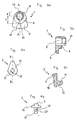
- the mechanical retaining means of the visors assembly comprise two pins 1, 1' engaged with the external visor 5, which project from the internal surface of this latter, and which are shaped to fit with two corresponding concave seats 13, 13' laterally provided along the edge of the internal visor 6.
- the dimensions of the internal visor 6 and of its lateral seats 13, 13', also the distance between the retainers 1, 1', and their shape, allow the retaining of the internal visor 6 in full contact with the internal surface of the external visor 5, in a elastically deformed structure of said internal visor 6, so to avoid humid air from flowing between the two visors 5, 6.
- the internal visor 6 which preferably may have a curvature radius R 6 higher than the curvature radius R 5 of the external visor 5, is elastically deformed (bended) during its assembling between the retainers 1, 1' and is kept in such deformed shape by the same retainers 1, 1' that impose a certain tension on the internal visor 6, thanks to their coupling with the correspondent seats 13, 13'.
- the elasticity of the material of the internal visor 6 and the bending to which the same internal visor 6 is subject permit an optimal retaining by the retainers 1, 1'.
- At least one of the retainers 1, 1' according to the present invention is constituted by a pin 1 which is mounted on the external visor 5 in a pivotable way around an axis X-X, incident the same external visor 5, and which comprise a portion for the engagement with the internal visor 6 constituted by a cylindrical body 4, having a circular base, eccentrically located with respect to the aforesaid rotation axis X-X of the pin 1.
- the circular base cylindrical body 4 has its symmetry axis parallel to the rotation axis X-X of the pin 1, standing aside from said rotation axis X-X, so to cam couple itself with a corresponding seat 13, 13' laterally provided on the same internal visor 6.
- the pin 1, as it will be clarified later, is also jointed with means 3 for transmitting the rotation which, advantageously, extend to the external side of the external visor 5, so to allow an easy operation by rotating the same pin 1 from the user.
- the rotation of the pin 1, thanks to the means 3, allows the cylindrical body 4 to gradually move from a first angular position, wherein a region (or at least a point) 14 for the loose engagement engages the respective seat 13 of the visor 6, to a second angular position wherein a different region (or point) 15 for the tight engagement engages the same seat 13, and vice versa.
- both the retainers 1, 1' are of the pivotable type having an eccentrically arranged cylindrical body for the engagement
- the contemporary angular positioning of the pins 1, 1' - achievable through the corresponding external means 3 for imposing the rotation of the pins 1, 1' in such a way that the regions of the eccentric cylindrical body 4 for the engagement with the minimum arm d engage the respective concave seat 13, 13' of the internal visor 6-leads to obtain the maximum distance between the retaining points of the same internal visor 6, in this way determining the application of minimum tension to this latter, i.e. leading to a loose linking between the pins 1, 1' and the visor 6.
- the rotation of one or both pins 1, 1' of the embodiment of the figures 1-6 permits to modify the engagement conditions of the internal visor 6 with the external visor 5 depending on the angular position achieved by the pins 1, 1', thus adjusting substantially in a continuous way (thanks to the eccentric arrangement of the body 4) the tension which the internal visor 6 may be subject to, when the visor 6 has an elastically deformed structure which put the same visor 6 in partial or full contact with the internal surface of the visor 5.
- each pin 1, 1' may also be provided with an upper blocking tab 9, suitable to avoid accidental disengagement of the seats 13, 13' with the engagement regions of the eccentric cylindrical bodies 4.
- Each blocking tab 9, provided above the internal surface of the visor 6, radially extends from the pin 1, 1' only according to an angular range (which comprises the region 15) wherein a tight coupling of the same eccentric cylindrical body 4 with the respective seat 13, 13' of the visor 6 occurs, in such a way that the tab 9 does not impede the removal of the visor when the region 14 for the loose engagement is brought into engagement with the respective seat 13, 13'.
- the pins 1, 1' are linked to the external visor 5 in a rotatable way with respect to the same visor, thanks to the engagement of such pins 1, 1' with the correspondent caps 2, 2', which extend to the outside of the visor 5 through respective holes 7 provided on the same visor 5.
- the geometry of the caps 2, 2' and the pins 1, 1' prevents the group constituted by each pin 1, 1' fixed to the respective external cap 2, 2' from slipping off from the hole 7 and at the same time permits the jointly rotation of such group around the axis X-X within the hole 7.
- each cap 2 may be integral with the external visor 5 and may engage the correspondent pin 1, 1' in such a way to allow its relative rotation with respect to the same cap 2, 2' which, thus, is fixed with respect to both visors 5, 6.
- each external cap 2, 2' comprises an upper portion 10 below which a cylinder 11 projects, provided with a spline 12 and with projections 20.
- the upper portion 10 comprises a shaped end 3 directed toward the outside of the external visor 5, which end is suitable to simplify the manual operation - in rotation around the axis X-X - of the cap 2 or 2' and the related pin 1 or 1' by the user and which is thus an essential part of the aforesaid means for imposing the rotation to the pin 1 or 1'.
- the lower cylinder 11 is shaped to internally engage a correspondent hollow seat 8 obtained within the pin 1, 1' and provided with a casing 21 for the spline 12.
- the hollow seat 8 also comprises grooves, not shown, suitable to snap couple with the projections 20, i.e. through interposition of parts upon the spring back of the same projections 20.
- the snap coupling of the pin 1, 1' with the cap 2, 2' ensures the axial engagement between the two parts, while the presence of the spline 12, which engage within the casing 21, provides the rotation of the cap 2 or 2' jointly with the pin 1 or 1'.
- the pin 1 may comprise an elastically deformable portion suitable to engage the hole 7 and provided with a grip end for the user.
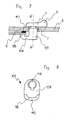
- the figures 7 and 8 show an alternate embodiment of the present invention particularly convenient when the internal visor 6 is partially brought in abutment with the internal surface of the external visor 5, preferably in correspondence of one peripheral edge.
- the external surface of the internal visor 6, as disclosed in the above mentioned patent US 6405373 (GRAU) may be provided with a frame 117 made of a material impermeable to fluids, such as a silicone material, arranged in correspondence of the peripheral edge of said external surface of the visor 6 and suitable to engage the external visor 5.
- each pin 101 of the embodiment shown in the figures 7 and 8 comprises a portion for the engagement with the internal visor 6 constituted by an upper tab 104 which extend beyond the visor 6 of an angular range around the rotation axis X-X of the pin 101.
- Such tab 104 provides a first region 115 for the tight engagement, which comprises a projection 116 shaped for engage the internal surface of the visor 6 so to transmit a certain pressure to the last, and a second region 114 for the loose engagement, without the elements for the engagement with the same visor 6.
- the pin 101 is coupled in a pivotable way to the external visor 5, through the hole 7 provided within the visor 5, by way of its coupling to an external cap 2, which is opportunely shaped for snap engage the same pin 101-using a spline - and which is provided with a shaped portion 3 for permitting the operation of the pin 101, by its rotation, from the outside of the external visor 5.
- pivotable pins of the above mentioned type - i.e. pins which comprise a portion for the engagement with the internal visor having at least a region for the loose engagement and a region for the tight engagement depending on the rotation angle achieved by a same pivotable pin and which are provided with means for imposing the rotation extending outside the external visor
- an anti-fog visors assembly of the type having an internal anti-fog visor which is placed on an external anti-scratch visor - permits to increase the tolerances of the parts of such visors assembly, with consequent economic advantages, permits to easily mount or dismount the internal visor without the necessity for preventively disengage the external visor from the helmet cover, and permits, when it is required, to adjust in a precise way the tension which the internal visor may be subject to.
Landscapes
- Helmets And Other Head Coverings (AREA)
- Vehicle Step Arrangements And Article Storage (AREA)
- Materials For Medical Uses (AREA)
- Devices For Indicating Variable Information By Combining Individual Elements (AREA)
- Chemically Coating (AREA)
- Mechanical Control Devices (AREA)
Claims (11)
- Zusammenbau von Helmvisieren mit Antibeschlageigenschaften, von der Art umfassend mindestens ein äußeres Visier (5) und mindestens ein inneres Visier (6), welches zumindest teilweise an der inneren Oberfläche des äußeren Visiers in Anlage gehalten wird mittels einer mechanischen Haltevorrichtung (1, 2; 1', 101), wobei die mechanische Haltevorrichtung mindestens zwei an das äußere Visier gekoppelte Befestigungsvorrichtungen (1, 1'; 101) umfasst, zwischen welchen das innere Visier angeordnet ist, wobei mindestens eine der zwei Befestigungsvorrichtungen ein Stift (1, 1'; 101) ist, relativ zum inneren Visier drehbar, dadurch gekennzeichnet, dass der drehbare Stift umfasst:• einen Bereich (4) zur Verrastung mit dem inneren Visier, welcher mindestens einen Teilbereich (14; 114) für das lose Verrasten und mindestens einen Teilbereich (15; 115) für das feste Verrasten aufweist, in Abhängigkeit vom von dem mindestens einen drehbaren Stift erreichten Drehwinkel; und• mindestens einen Lappen (9) zum Sperren des inneren Visiers, angeordnet auf der Innenseite des inneren Visiers (6).und dadurch gekennzeichnet, dass die mechanische Haltevorrichtung außerdem mindestens eine äußere Verschlusskappe (2, 2') umfasst, angeordnet auf der Außenseite des äußeren Visiers (5) und an den mindestens einen drehbaren Stift durch ein Loch (7) befestigt, bereitgestellt in dem äußeren Visier; wobei die äußere Verschlusskappe (2) einen geformten Bereich (3) umfasst, um die Drehung des drehbaren Stifts manuell zu erzwingen.
- Zusammenbau von Helmvisieren mit Antibeschlageigenschaften nach Anspruch 1, dadurch gekennzeichnet, dass die mechanische Haltevorrichtung außerdem mindestens eine Aufnahme (13, 12') umfasst, seitlich im inneren Visier bereitgestellt, zur Verrastung mit dem drehbaren Stift, wobei der Zusammenbau von Visieren mit Antibeschlageigenschaften dadurch gekennzeichnet ist, dass der Bereich zur Verrastung des drehbaren Stifts in Bezug auf die entsprechende Aufnahme des inneren Visiers eine exzentrische Form aufweist.
- Zusammenbau von Helmvisieren mit Antibeschlageigenschaften nach Anspruch 2, dadurch gekennzeichnet, dass der Lappen (9) zum Sperren des inneren Visiers oberhalb des Bereichs zur Verrastung mit dem inneren Visier angeordnet ist.
- Zusammenbau von Helmvisieren mit Antibeschlageigenschaften nach einem der vorangegangenen Ansprüche 2 oder 3, dadurch gekennzeichnet, dass der Bereich zur exzentrischen Verrastung mindestens eine Winkelstellung zur Demontage aufweist, im wesentlichen zusammenfallend mit dem mindestens einen Teilbereich (14) für das lose Verrasten, wobei der Abstand (d) zwischen der Drehachse des drehbaren Stifts und dem Kupplungspunkt mit der entsprechenden Aufnahme des inneren Visiers minimal ist, womit der drehbare Stift auf das innere Visier keinerlei Spannung, oder eine minimale Spannung, ausübt.
- Zusammenbau von Helmvisieren mit Antibeschlageigenschaften nach Anspruch 1, dadurch gekennzeichnet, dass der Sperrlappen (104) oberhalb eines entsprechenden Teilbereichs zur Verrastung mit dem inneren Visier angeordnet sein kann, und wobei der Sperrlappen mit dem inneren Visier ausschließlich über einen vorgegebenen Winkelbereich hinweg verrastet, welcher durch den drehbaren Stift erreicht wird.
- Zusammenbau von Helmvisieren mit Antibeschlageigenschaften nach einem der vorangegangenen Ansprüche, dadurch gekennzeichnet, dass dieser zwei Stifte umfasst, drehbar relativ zu dem inneren Visier, wobei jeder der zwei drehbaren Stifte bereitgestellt wird mit einem Bereich zur Verrastung mit dem inneren Visier, welcher zumindest einen Teilbereich für das lose Verrasten und zumindest einen Teilbereich für das feste Verrasten bereitstellt, abhängig vom Drehwinkel, welcher durch den mindestens einen drehbaren Stift erreicht wird.
- Zusammenbau von Helmvisieren mit Antibeschlageigenschaften nach einem der vorangegangenen Ansprüche, dadurch gekennzeichnet, dass die äußere Verschlusskappe durch einen Schnappverschluss an dem drehbaren Stift fixierbar ist.
- Zusammenbau von Helmvisieren nach einem der vorangegangenen Ansprüche, dadurch gekennzeichnet, dass die äußere Verschlusskappe ausgeformt ist, um das axiale Gleiten des mindestens einen drehbaren Stifts relativ zum äußeren Visier zu verhindern.
- Zusammenbau von Helmvisieren mit Antibeschlageigenschaften nach einem der vorangegangenen Ansprüche, dadurch gekennzeichnet, dass die äußere Oberfläche des inneren Visiers nahezu vollständig an der inneren Oberfläche des äußeren Visiers anliegt.
- Zusammenbau von Helmvisieren mit Antibeschlageigenschaften nach einem der vorangegangenen Ansprüche 1 bis 8, wobei die äußere Oberfläche des inneren Visiers an der inneren Oberfläche des äußeren Visiers nur dem umlaufenden Rand (117) desselben entsprechend anliegt.
- Zusammenbau von Helmvisieren mit Antibeschlageigenschaften nach einem der vorangegangenen Ansprüche, wobei der Krümmungsradius (R6) des inneren Visiers größer ist als der Krümmungsradius (R5) des äußeren Visiers.
Applications Claiming Priority (2)
| Application Number | Priority Date | Filing Date | Title |
|---|---|---|---|
| IT000411U ITMI20030411U1 (it) | 2003-09-12 | 2003-09-12 | Sistema di visiere anti-condensa |
| ITMI20030411U | 2003-09-12 |
Publications (2)
| Publication Number | Publication Date |
|---|---|
| EP1514486A1 EP1514486A1 (de) | 2005-03-16 |
| EP1514486B1 true EP1514486B1 (de) | 2008-05-14 |
Family
ID=30012678
Family Applications (1)
| Application Number | Title | Priority Date | Filing Date |
|---|---|---|---|
| EP04021509A Expired - Lifetime EP1514486B1 (de) | 2003-09-12 | 2004-09-10 | Helmvisier mit Antibeschlageigenschaften |
Country Status (9)
| Country | Link |
|---|---|
| US (1) | US7036152B2 (de) |
| EP (1) | EP1514486B1 (de) |
| JP (1) | JP5062949B2 (de) |
| AT (1) | ATE394955T1 (de) |
| AU (1) | AU2004210530B2 (de) |
| CA (1) | CA2481159C (de) |
| DE (1) | DE602004013689D1 (de) |
| ES (1) | ES2305634T3 (de) |
| IT (1) | ITMI20030411U1 (de) |
Families Citing this family (26)
| Publication number | Priority date | Publication date | Assignee | Title |
|---|---|---|---|---|
| US7895678B2 (en) * | 2007-08-06 | 2011-03-01 | Bell Sports, Inc. | Helmet with improved shield mount and precision shield control |
| GB2453141A (en) * | 2007-09-27 | 2009-04-01 | Hd Inspiration B V | Method of forming a visor |
| ITBG20070050A1 (it) * | 2007-10-31 | 2009-05-01 | Ci Erre E S R L | Struttura di visiera |
| JP5103290B2 (ja) * | 2008-06-10 | 2012-12-19 | 株式会社Shoei | ヘルメット用またはゴーグル用のシールド構造およびこのようなシールド構造を備えているヘルメット |
| AU2009266816B2 (en) | 2008-07-03 | 2014-09-18 | Oakley, Inc. | Floating lens mounting system |
| US8469510B2 (en) | 2009-01-09 | 2013-06-25 | Oakley, Inc. | Eyewear with enhanced ballistic resistance |
| KR101551519B1 (ko) | 2009-01-30 | 2015-09-09 | 알파마이크론, 인크. | 부착할 수 있는 광학 소자 장치 및 방법 |
| DE202009010212U1 (de) | 2009-07-28 | 2010-01-07 | Huynh, Quang-Ut | Elektrisches Dünnschichtheizsystem für Helmvisiere |
| CA2731186A1 (en) * | 2010-02-08 | 2011-08-08 | Afx North America Inc. | Helmet face shield |
| USD658812S1 (en) | 2010-02-12 | 2012-05-01 | Alphamicron, Inc. | Optical element for a helmet visor |
| US8881316B2 (en) * | 2010-03-19 | 2014-11-11 | Oakley, Inc. | Eyewear with rigid lens support |
| JP5468469B2 (ja) | 2010-06-03 | 2014-04-09 | 株式会社Shoei | シールドへの防曇シート取り付け構造 |
| WO2014036274A2 (en) | 2012-08-31 | 2014-03-06 | Oakley, Inc. | Eyewear having multiple ventilation states |
| EP2919728B1 (de) | 2012-11-13 | 2017-12-20 | Alphamicron Incorporated | Anordnungen für fixierbares optisches element und verfahren |
| FR2997824A1 (fr) * | 2012-11-13 | 2014-05-16 | Stand 21 | Visiere renforcee pour casque de pilote de competition |
| WO2014093514A1 (en) | 2012-12-11 | 2014-06-19 | Oakley, Inc. | Eyewear with outriggers |
| WO2014138159A1 (en) | 2013-03-07 | 2014-09-12 | Oakley, Inc. | Regeneratable ant-fogging element for goggle |
| AU2015235947B2 (en) | 2014-03-27 | 2017-12-07 | Oakley, Inc. | Mounting mechanism for eyewear |
| EP3272241B1 (de) * | 2015-03-19 | 2020-09-23 | Wins Japan Co. Ltd. | Befestigungsfolie, helm, brille und verfahren zur befestigung einer antibeschlagsfolie |
| EP3360006A1 (de) | 2015-10-09 | 2018-08-15 | Oakley, Inc. | Am kopf getragene gestelle mit passiver entlüftung und abnehmbarer linse |
| US9709817B2 (en) | 2015-12-07 | 2017-07-18 | Oakley, Inc. | Eyewear retention devices and methods |
| WO2017100456A1 (en) | 2015-12-08 | 2017-06-15 | Oakley, Inc. | Eyewear traction devices and methods |
| US10359642B2 (en) | 2016-04-22 | 2019-07-23 | Oakley, Inc. | Mounting mechanism for eyewear |
| US12035765B2 (en) * | 2019-05-28 | 2024-07-16 | Honeywell International Inc. | Protective face shield assembly |
| US20220152432A1 (en) * | 2020-09-23 | 2022-05-19 | Larry Ray Kane | Face mask |
| JP7686602B2 (ja) * | 2022-05-30 | 2025-06-02 | 株式会社Shoei | シート取付構造及びヘルメット |
Family Cites Families (14)
| Publication number | Priority date | Publication date | Assignee | Title |
|---|---|---|---|---|
| US2952853A (en) * | 1956-06-26 | 1960-09-20 | Scott Aviation Corp | Means for detachably attaching a lens to a face mask |
| US3805294A (en) * | 1972-05-04 | 1974-04-23 | Ballard E Co | Face shield mounting structure |
| FR2215980B1 (de) * | 1973-02-01 | 1978-11-10 | Draegerwerk Ag | |
| FR2373979A1 (fr) * | 1975-12-30 | 1978-07-13 | Norton Co | Casque de protection avec visiere |
| DE3306103C2 (de) * | 1982-04-26 | 1985-09-12 | Yamamoto Kogaku Co., Ltd., Higashi-Osaka, Osaka | Vorrichtung zum Beheizen des ein Sichtfenster eines Schutzhelmes abdeckenden Schutzglases |
| JPS63309612A (ja) * | 1987-06-09 | 1988-12-16 | 新井 理夫 | ヘルメットにおけるシ−ルドの取付構造 |
| US4989274A (en) * | 1989-11-13 | 1991-02-05 | Sport Eyes Enterprises, Inc. | Sports goggles |
| NL9402012A (nl) * | 1994-11-30 | 1996-07-01 | Dereks Patent Bv | Anti-condens vizier. |
| US6035451A (en) * | 1998-03-10 | 2000-03-14 | Minnesota Mining And Manufacturing Company | Protective helmet system with cam for attaching first and second face shields thereto |
| US6102033A (en) * | 1998-03-10 | 2000-08-15 | 3M Innovative Properties Company | Attachment system for replacement helmet respirator lens |
| NL1012896C2 (nl) * | 1999-08-24 | 2001-03-06 | Dereks Patent Bv | Viziersamenstel. |
| DE19952219C2 (de) * | 1999-10-29 | 2003-07-03 | Uvex Sports Gmbh & Co Kg | Visier für einen Helm, insbesondere einen Motorradhelm |
| US7003802B2 (en) * | 2001-04-23 | 2006-02-28 | Jt Usa, Llc | Face mask with detachable eye shield |
| JP2003016510A (ja) * | 2001-07-02 | 2003-01-17 | Fuji Electric Co Ltd | 自動販売機のディスプレイ装置 |
-
2003
- 2003-09-12 IT IT000411U patent/ITMI20030411U1/it unknown
-
2004
- 2004-09-10 AT AT04021509T patent/ATE394955T1/de not_active IP Right Cessation
- 2004-09-10 CA CA2481159A patent/CA2481159C/en not_active Expired - Lifetime
- 2004-09-10 ES ES04021509T patent/ES2305634T3/es not_active Expired - Lifetime
- 2004-09-10 DE DE602004013689T patent/DE602004013689D1/de not_active Expired - Lifetime
- 2004-09-10 EP EP04021509A patent/EP1514486B1/de not_active Expired - Lifetime
- 2004-09-10 JP JP2004263402A patent/JP5062949B2/ja not_active Expired - Fee Related
- 2004-09-10 US US10/937,884 patent/US7036152B2/en not_active Expired - Lifetime
- 2004-09-10 AU AU2004210530A patent/AU2004210530B2/en not_active Expired
Also Published As
| Publication number | Publication date |
|---|---|
| ITMI20030411U1 (it) | 2005-03-13 |
| DE602004013689D1 (de) | 2008-06-26 |
| AU2004210530A1 (en) | 2005-04-07 |
| CA2481159C (en) | 2012-12-11 |
| CA2481159A1 (en) | 2005-03-11 |
| AU2004210530B2 (en) | 2010-01-28 |
| ITMI20030411V0 (it) | 2003-09-12 |
| ES2305634T3 (es) | 2008-11-01 |
| US20050066427A1 (en) | 2005-03-31 |
| JP5062949B2 (ja) | 2012-10-31 |
| EP1514486A1 (de) | 2005-03-16 |
| ATE394955T1 (de) | 2008-05-15 |
| US7036152B2 (en) | 2006-05-02 |
| JP2005097823A (ja) | 2005-04-14 |
Similar Documents
| Publication | Publication Date | Title |
|---|---|---|
| EP1514486B1 (de) | Helmvisier mit Antibeschlageigenschaften | |
| US6105177A (en) | Protective goggles | |
| US7000262B2 (en) | Flexible ratchet mechanism for the headband of protective headgear | |
| US20220248797A1 (en) | Hard Hat Face Shield Attachment System | |
| US8250669B2 (en) | Safety helmet with supplemental inner visor | |
| US20220039502A1 (en) | Skull mounting system for headgear, respiratory hood with headgear and method for fastening of headgear | |
| KR20090046709A (ko) | 안경 | |
| EP4154747B1 (de) | Fahrradhelm mit brillenhalterung | |
| EP1023627B1 (de) | Ein brillengestell, eine brille und verfahren zur herstellung einer brille | |
| EP4588535A1 (de) | Schwimmbrille | |
| CN120284036A (zh) | 安全帽系统 | |
| EP4368051A1 (de) | Schutzhelmschale und zugehöriger schutzhelm | |
| EP0184929B1 (de) | Atemschutzgerät mit Befestigungseinrichtung für Korrekturgläser | |
| EP4245180B1 (de) | Vorrichtung zum öffnen/schliessen des visiers eines helms | |
| CN116744815A (zh) | 安全帽护面罩附接系统 | |
| US20260000146A1 (en) | Helmet fitting system and manufacturing method therefor | |
| WO2022170192A1 (en) | Hard hat face shield attachment system | |
| JP2025500238A (ja) | 改善された取り付け具を有するバイザ組立体 | |
| EP0366409A2 (de) | Sichtkorrekturlinsenmontagesystem für Atemgerät | |
| JPH07281103A (ja) | 双眼鏡の視度補正機構 | |
| HK1028916B (en) | An eyeglass frame, an eyeglass, and a method of manufacturing an eyeglass | |
| HK1165015B (en) | Eyeglass with enhanced ballistic resistance |
Legal Events
| Date | Code | Title | Description |
|---|---|---|---|
| PUAI | Public reference made under article 153(3) epc to a published international application that has entered the european phase |
Free format text: ORIGINAL CODE: 0009012 |
|
| AK | Designated contracting states |
Kind code of ref document: A1 Designated state(s): AT BE BG CH CY CZ DE DK EE ES FI FR GB GR HU IE IT LI LU MC NL PL PT RO SE SI SK TR |
|
| AX | Request for extension of the european patent |
Extension state: AL HR LT LV MK |
|
| 17P | Request for examination filed |
Effective date: 20050725 |
|
| AKX | Designation fees paid |
Designated state(s): AT BE BG CH CY CZ DE DK EE ES FI FR GB GR HU IE IT LI LU MC NL PL PT RO SE SI SK TR |
|
| 17Q | First examination report despatched |
Effective date: 20051107 |
|
| GRAP | Despatch of communication of intention to grant a patent |
Free format text: ORIGINAL CODE: EPIDOSNIGR1 |
|
| GRAS | Grant fee paid |
Free format text: ORIGINAL CODE: EPIDOSNIGR3 |
|
| GRAA | (expected) grant |
Free format text: ORIGINAL CODE: 0009210 |
|
| AK | Designated contracting states |
Kind code of ref document: B1 Designated state(s): AT BE BG CH CY CZ DE DK EE ES FI FR GB GR HU IE IT LI LU MC NL PL PT RO SE SI SK TR |
|
| REG | Reference to a national code |
Ref country code: GB Ref legal event code: FG4D |
|
| REG | Reference to a national code |
Ref country code: CH Ref legal event code: EP |
|
| REG | Reference to a national code |
Ref country code: IE Ref legal event code: FG4D Free format text: LANGUAGE OF EP DOCUMENT: FRENCH |
|
| REF | Corresponds to: |
Ref document number: 602004013689 Country of ref document: DE Date of ref document: 20080626 Kind code of ref document: P |
|
| PG25 | Lapsed in a contracting state [announced via postgrant information from national office to epo] |
Ref country code: SI Free format text: LAPSE BECAUSE OF FAILURE TO SUBMIT A TRANSLATION OF THE DESCRIPTION OR TO PAY THE FEE WITHIN THE PRESCRIBED TIME-LIMIT Effective date: 20080514 |
|
| PG25 | Lapsed in a contracting state [announced via postgrant information from national office to epo] |
Ref country code: FI Free format text: LAPSE BECAUSE OF FAILURE TO SUBMIT A TRANSLATION OF THE DESCRIPTION OR TO PAY THE FEE WITHIN THE PRESCRIBED TIME-LIMIT Effective date: 20080514 |
|
| REG | Reference to a national code |
Ref country code: ES Ref legal event code: FG2A Ref document number: 2305634 Country of ref document: ES Kind code of ref document: T3 |
|
| NLV1 | Nl: lapsed or annulled due to failure to fulfill the requirements of art. 29p and 29m of the patents act | ||
| PG25 | Lapsed in a contracting state [announced via postgrant information from national office to epo] |
Ref country code: PL Free format text: LAPSE BECAUSE OF FAILURE TO SUBMIT A TRANSLATION OF THE DESCRIPTION OR TO PAY THE FEE WITHIN THE PRESCRIBED TIME-LIMIT Effective date: 20080514 Ref country code: NL Free format text: LAPSE BECAUSE OF FAILURE TO SUBMIT A TRANSLATION OF THE DESCRIPTION OR TO PAY THE FEE WITHIN THE PRESCRIBED TIME-LIMIT Effective date: 20080514 Ref country code: AT Free format text: LAPSE BECAUSE OF FAILURE TO SUBMIT A TRANSLATION OF THE DESCRIPTION OR TO PAY THE FEE WITHIN THE PRESCRIBED TIME-LIMIT Effective date: 20080514 |
|
| PG25 | Lapsed in a contracting state [announced via postgrant information from national office to epo] |
Ref country code: DK Free format text: LAPSE BECAUSE OF FAILURE TO SUBMIT A TRANSLATION OF THE DESCRIPTION OR TO PAY THE FEE WITHIN THE PRESCRIBED TIME-LIMIT Effective date: 20080514 Ref country code: CZ Free format text: LAPSE BECAUSE OF FAILURE TO SUBMIT A TRANSLATION OF THE DESCRIPTION OR TO PAY THE FEE WITHIN THE PRESCRIBED TIME-LIMIT Effective date: 20080514 Ref country code: PT Free format text: LAPSE BECAUSE OF FAILURE TO SUBMIT A TRANSLATION OF THE DESCRIPTION OR TO PAY THE FEE WITHIN THE PRESCRIBED TIME-LIMIT Effective date: 20081014 Ref country code: SE Free format text: LAPSE BECAUSE OF FAILURE TO SUBMIT A TRANSLATION OF THE DESCRIPTION OR TO PAY THE FEE WITHIN THE PRESCRIBED TIME-LIMIT Effective date: 20080814 |
|
| PG25 | Lapsed in a contracting state [announced via postgrant information from national office to epo] |
Ref country code: RO Free format text: LAPSE BECAUSE OF FAILURE TO SUBMIT A TRANSLATION OF THE DESCRIPTION OR TO PAY THE FEE WITHIN THE PRESCRIBED TIME-LIMIT Effective date: 20080514 Ref country code: SK Free format text: LAPSE BECAUSE OF FAILURE TO SUBMIT A TRANSLATION OF THE DESCRIPTION OR TO PAY THE FEE WITHIN THE PRESCRIBED TIME-LIMIT Effective date: 20080514 Ref country code: BE Free format text: LAPSE BECAUSE OF FAILURE TO SUBMIT A TRANSLATION OF THE DESCRIPTION OR TO PAY THE FEE WITHIN THE PRESCRIBED TIME-LIMIT Effective date: 20080514 |
|
| PLBE | No opposition filed within time limit |
Free format text: ORIGINAL CODE: 0009261 |
|
| STAA | Information on the status of an ep patent application or granted ep patent |
Free format text: STATUS: NO OPPOSITION FILED WITHIN TIME LIMIT |
|
| 26N | No opposition filed |
Effective date: 20090217 |
|
| PG25 | Lapsed in a contracting state [announced via postgrant information from national office to epo] |
Ref country code: EE Free format text: LAPSE BECAUSE OF FAILURE TO SUBMIT A TRANSLATION OF THE DESCRIPTION OR TO PAY THE FEE WITHIN THE PRESCRIBED TIME-LIMIT Effective date: 20080514 Ref country code: BG Free format text: LAPSE BECAUSE OF FAILURE TO SUBMIT A TRANSLATION OF THE DESCRIPTION OR TO PAY THE FEE WITHIN THE PRESCRIBED TIME-LIMIT Effective date: 20080814 Ref country code: MC Free format text: LAPSE BECAUSE OF NON-PAYMENT OF DUE FEES Effective date: 20080930 |
|
| REG | Reference to a national code |
Ref country code: CH Ref legal event code: PL |
|
| REG | Reference to a national code |
Ref country code: IE Ref legal event code: MM4A |
|
| PG25 | Lapsed in a contracting state [announced via postgrant information from national office to epo] |
Ref country code: IE Free format text: LAPSE BECAUSE OF NON-PAYMENT OF DUE FEES Effective date: 20080910 |
|
| PG25 | Lapsed in a contracting state [announced via postgrant information from national office to epo] |
Ref country code: LI Free format text: LAPSE BECAUSE OF NON-PAYMENT OF DUE FEES Effective date: 20080930 Ref country code: CH Free format text: LAPSE BECAUSE OF NON-PAYMENT OF DUE FEES Effective date: 20080930 |
|
| PG25 | Lapsed in a contracting state [announced via postgrant information from national office to epo] |
Ref country code: HU Free format text: LAPSE BECAUSE OF FAILURE TO SUBMIT A TRANSLATION OF THE DESCRIPTION OR TO PAY THE FEE WITHIN THE PRESCRIBED TIME-LIMIT Effective date: 20081115 Ref country code: CY Free format text: LAPSE BECAUSE OF FAILURE TO SUBMIT A TRANSLATION OF THE DESCRIPTION OR TO PAY THE FEE WITHIN THE PRESCRIBED TIME-LIMIT Effective date: 20080514 Ref country code: LU Free format text: LAPSE BECAUSE OF NON-PAYMENT OF DUE FEES Effective date: 20080910 |
|
| PG25 | Lapsed in a contracting state [announced via postgrant information from national office to epo] |
Ref country code: TR Free format text: LAPSE BECAUSE OF FAILURE TO SUBMIT A TRANSLATION OF THE DESCRIPTION OR TO PAY THE FEE WITHIN THE PRESCRIBED TIME-LIMIT Effective date: 20080514 |
|
| PG25 | Lapsed in a contracting state [announced via postgrant information from national office to epo] |
Ref country code: GR Free format text: LAPSE BECAUSE OF FAILURE TO SUBMIT A TRANSLATION OF THE DESCRIPTION OR TO PAY THE FEE WITHIN THE PRESCRIBED TIME-LIMIT Effective date: 20080815 |
|
| REG | Reference to a national code |
Ref country code: DE Ref legal event code: R082 Ref document number: 602004013689 Country of ref document: DE Representative=s name: GODEMEYER BLUM LENZE PARTNERSCHAFT, PATENTANWA, DE Ref country code: DE Ref legal event code: R082 Ref document number: 602004013689 Country of ref document: DE Representative=s name: GODEMEYER BLUM LENZE PATENTANWAELTE, PARTNERSC, DE |
|
| REG | Reference to a national code |
Ref country code: FR Ref legal event code: PLFP Year of fee payment: 12 |
|
| REG | Reference to a national code |
Ref country code: FR Ref legal event code: PLFP Year of fee payment: 13 |
|
| REG | Reference to a national code |
Ref country code: FR Ref legal event code: PLFP Year of fee payment: 14 |
|
| REG | Reference to a national code |
Ref country code: FR Ref legal event code: PLFP Year of fee payment: 15 |
|
| P01 | Opt-out of the competence of the unified patent court (upc) registered |
Effective date: 20230527 |
|
| PGFP | Annual fee paid to national office [announced via postgrant information from national office to epo] |
Ref country code: IT Payment date: 20230908 Year of fee payment: 20 Ref country code: GB Payment date: 20230913 Year of fee payment: 20 |
|
| PGFP | Annual fee paid to national office [announced via postgrant information from national office to epo] |
Ref country code: FR Payment date: 20230816 Year of fee payment: 20 Ref country code: DE Payment date: 20230901 Year of fee payment: 20 |
|
| PGFP | Annual fee paid to national office [announced via postgrant information from national office to epo] |
Ref country code: ES Payment date: 20231003 Year of fee payment: 20 |
|
| REG | Reference to a national code |
Ref country code: DE Ref legal event code: R071 Ref document number: 602004013689 Country of ref document: DE |
|
| REG | Reference to a national code |
Ref country code: ES Ref legal event code: FD2A Effective date: 20240927 |
|
| REG | Reference to a national code |
Ref country code: GB Ref legal event code: PE20 Expiry date: 20240909 |
|
| PG25 | Lapsed in a contracting state [announced via postgrant information from national office to epo] |
Ref country code: GB Free format text: LAPSE BECAUSE OF EXPIRATION OF PROTECTION Effective date: 20240909 |
|
| PG25 | Lapsed in a contracting state [announced via postgrant information from national office to epo] |
Ref country code: ES Free format text: LAPSE BECAUSE OF EXPIRATION OF PROTECTION Effective date: 20240911 |
|
| PG25 | Lapsed in a contracting state [announced via postgrant information from national office to epo] |
Ref country code: GB Free format text: LAPSE BECAUSE OF EXPIRATION OF PROTECTION Effective date: 20240909 Ref country code: ES Free format text: LAPSE BECAUSE OF EXPIRATION OF PROTECTION Effective date: 20240911 |