EP1513725B1 - Systeme et procede pour l'inspection de poutre par technologie de fibres optiques - Google Patents
Systeme et procede pour l'inspection de poutre par technologie de fibres optiques Download PDFInfo
- Publication number
- EP1513725B1 EP1513725B1 EP03770227A EP03770227A EP1513725B1 EP 1513725 B1 EP1513725 B1 EP 1513725B1 EP 03770227 A EP03770227 A EP 03770227A EP 03770227 A EP03770227 A EP 03770227A EP 1513725 B1 EP1513725 B1 EP 1513725B1
- Authority
- EP
- European Patent Office
- Prior art keywords
- leg
- support member
- flange
- gap
- clip
- Prior art date
- Legal status (The legal status is an assumption and is not a legal conclusion. Google has not performed a legal analysis and makes no representation as to the accuracy of the status listed.)
- Expired - Lifetime
Links
Images
Classifications
-
- G—PHYSICS
- G01—MEASURING; TESTING
- G01N—INVESTIGATING OR ANALYSING MATERIALS BY DETERMINING THEIR CHEMICAL OR PHYSICAL PROPERTIES
- G01N21/00—Investigating or analysing materials by the use of optical means, i.e. using sub-millimetre waves, infrared, visible or ultraviolet light
- G01N21/84—Systems specially adapted for particular applications
- G01N21/88—Investigating the presence of flaws or contamination
- G01N21/8803—Visual inspection
-
- G—PHYSICS
- G01—MEASURING; TESTING
- G01N—INVESTIGATING OR ANALYSING MATERIALS BY DETERMINING THEIR CHEMICAL OR PHYSICAL PROPERTIES
- G01N21/00—Investigating or analysing materials by the use of optical means, i.e. using sub-millimetre waves, infrared, visible or ultraviolet light
- G01N21/84—Systems specially adapted for particular applications
- G01N21/88—Investigating the presence of flaws or contamination
- G01N21/95—Investigating the presence of flaws or contamination characterised by the material or shape of the object to be examined
- G01N21/954—Inspecting the inner surface of hollow bodies, e.g. bores
- G01N2021/9542—Inspecting the inner surface of hollow bodies, e.g. bores using a probe
- G01N2021/9546—Inspecting the inner surface of hollow bodies, e.g. bores using a probe with remote light transmitting, e.g. optical fibres
Definitions
- the invention relates generally to the use of micro fiber-optic technology to inspect a beam surface. More specifically, the invention relates to inspecting a concealed surface of a beam by inserting a micro fiber-optic thread of a micro fiber-optic borescope between the beam and a structure concealing the surface.
- a beam such as a floor beam of an aircraft
- maintenance programs for a commercial airline aircraft typically require heavy maintenance checks to be performed between every 5 to 7 years.
- the floor structure is inspected for corrosion damage by completely removing everything that is mounted to the floor beams, including floor panels and all structures above the floor panels.
- Corrosion damage to the aluminum floor beams of an aircraft most frequently happens around 'wet' areas, near entry doors and under lavatories and galleys, which can leak fluids.
- Such corrosion damage is most frequently found on the upper surface of the aluminum floor beam, and particularly around the fastener holes used to attach the floor panels to the floor beams.
- the airline inspection crew In order to inspect the upper surface of the floor beam, the airline inspection crew must remove the lavatories, seats, galleys, closets, etc., and then remove the floor panels. On the average, removing one galley, taking up the floor panels, inspecting the beams, replacing beams or treating the beams with a corrosion inhibiting compound, and then replacing the floor and galley, can require over 600 hours of labor per galley (or lavatory, etc. ), thereby making such an inspection/repair process very costly.
- WO 00/50304 A discloses an aircraft visualisation system comprising a camera mounted on the distal end of a support.
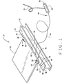
- Figure 1 is a perspective view of a system for inspecting a surface of a floor beam covered by a floor panel, in accordance with a preferred embodiment of the present invention
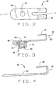
- Figure 2 is a top view of a nut clip included in the system shown in Figure 1 ;
- Figure 3 is cross-sectional side view of the nut clip taken in accordance with section line 3-3 shown in Figure 2 ;
- Figure 4 is perspective view of a spacer included in the system shown in Figure 1 .
- FIG. 1 is a perspective view of a system 10, in accordance with a preferred embodiment of the present invention, for inspecting an upper surface 14 of a floor beam 18 covered by a floor panel 22.
- the term "floor beam” is intended to include any beam or structural member used to support floor panel 22, for example, in the context of aircraft, the term “floor beam” includes aircraft seat tracks.
- Inspection system 10 includes at least one nut clip 26, at least one spacer 30 and a micro fiber-optic borescope 34.
- Nut clip 26 attaches to a floor beam flange 36 and is used to mount floor panel 22 to floor beam 18 utilizing a fastener 38 that couples with nut clip 26. Additionally, nut clip 26 creates a gap 42 between floor panel 22 and beam upper surface 14, Nut clip 26 is described in detail below in reference to Figures 2 and 3 .
- Flange 36 includes the beam upper surface 14, a lower surface 46 and a plurality of flange apertures 48 used in mounting floor panel 22 to beam 18.
- Each floor panel 22 is coupled to floor beam 18 by attaching a pair of nut clips 26 to floor beam flange 36 such that a panel aperture 50 in each of the two corners along one edge of floor panel 22 align with the nut clips 26 and one of beam apertures 48. Then a fastener 38 is inserted through the panel apertures 50 at each corner of panel 22, through the related flange aperture 48 and threaded into the related nut clip 26.
- Fastener 38 may comprise any fastener suitable to mount floor panel 22 to beam 18 via nut clip 26, such as a bolt, a screw, or a high lock.
- At least one spacer 30 is installed between floor panel 22 and beam upper surface 14 and positioned between the nut clips 26 at each corner of panel 22, thereby creating gap 42 in the area between nut clips 26.
- Spacer 30 is described in detail below in reference to Figure 4 .
- Micro fiber-optic borescope 34 is a hand held device that includes a micro fiber-optic thread 54 and a borescope viewing device 58. When an imaging end 60 of micro fiber-optic thread 54 is inserted into gap 42, images of beam upper surface 14 are transmitted through micro fiber-optic thread 54 to viewing device 58 where an inspector views the transmitted images.
- micro fiber-optic borescope 34 may include an auxiliary device cable 61 used to connect borescope 34 to peripheral remote devices (not shown) such as a viewing monitor or an image recording device.
- Figure 2 is a top view of nut clip 26 and Figure 3 is a cross-sectional side view of nut clip 26 along line 3-3 in Figure 2 .
- Nut clip 26 includes an upper leg 62, a lower leg 66 that includes a hole 64 and a means 65 for coupling fastener 38 with nut clip 26, and an intermediate section 68 that joins upper leg 62 and lower leg 66.
- lower leg 66 includes a first section 70 and a second section 74 that includes the fastener coupling means 65.
- the fastener coupling means 65 includes a nut housing 78 and a nut 82 enclosed in housing 78.
- the fastener coupling means includes a nut attached to lower leg second section 74.
- hole 64 is threaded and the fastener coupling means includes threaded hole 64.
- Nut clip 26 attaches to floor beam flange 36 by inserting flange 36 between nut clip upper leg 62 and lower leg 66 such that upper leg 62 is in frictional contact with beam upper surface 14, lower leg 66 is in frictional contact with flange lower surface 46, and nut clip hole 64 aligns with one of flange apertures 48. Additionally, upper leg 62 has a shorter length than lower leg 66 such that when nut clip 26 is placed on floor beam flange 36 the aperture 48 that aligns with nut clip hole 64 is free from interference by upper leg 62. Furthermore, nut clip upper leg 62 creates gap 42 in the area adjacent upper leg 62.
- upper leg 62 allows a person inspecting floor beam 18 to insert borescope micro fiber optic thread 54 into gap 42 and view beam upper surface 14 around beam aperture 48, which is an area where corrosion and damage are more likely to occur.
- FIG 4 is a perspective view of spacer 30 (shown in Figure 1 ), in accordance with a preferred embodiment of the present invention.
- the preferred embodiment includes at least one spacer 30.
- spacer 30 includes a first leg 86, a second leg 90 and an intermediate section 94 that joins first leg 86 and second leg 90.
- spacer 30 is attached to beam flange 36 between the nut clips 26 positioned at the two corners along one side of the floor panel 22.
- a plurality of spacers 30 are attached to flange 36 at predetermined intervals between nut clips 26.
- Spacer 30 attaches to floor beam flange 36 by inserting flange 36 between spacer first leg 86 and second leg 90 such that first leg 86 is in frictional contact with beam upper surface 14 and second leg 90 is in frictional contact with flange lower surface 46. Additionally, spacer first leg 86 creates gap 42 in the area adjacent first leg 86, thereby allowing a person inspecting floor beam 18 to insert borescope micro fiber optic thread 54 into gap 42 and view beam upper surface 14. Preferably first leg 86 is shorter in length than second leg 90, However, it is envisioned that first leg 86 could alternately have a length, equal to or longer than spacer second leg 90.
- spacer 30 comprises a shim that is removably inserted between floor panel 22 and beam upper surface 14 during inspection of floor beam 18. Therefore, when floor beam 18 is to be inspected, spacer 30 is temporarily inserted between floor panel 22 and beam upper surface 14, thereby creating gap 42. After gap 42 is created an inspector can insert micro fiber-optic thread 54 into gap 42 and view upper surface 14 via viewing device 58.
- Spacer 30 can be any shape suitable to be removably inserted between floor panel 22 and beam upper surface 14 to create gap 42.
- shim 30 can be rectangular, oval or round, and have a constant thickness or be wedge shaped. Additionally, it is envisioned that spacer 30 may include a handle to aid in its insertion and removal.
- an inspector accesses the floor beams 18 from under the beams 18, for example from the cargo area of an aircraft.
- the inspector then inserts the imaging end 60 of micro fiber-optic thread 54 into gap 42. Images are transmitted from imaging end 60 through micro fiber-optic thread 54 to viewing device 58.
- Viewing device then creates high resolution video images of the images received and displays the images on an eye piece viewer 94 (shown in Figure 1 ).
- the inspector views the condition of beam upper surface 14.
- the images can be viewed on a larger viewing screen by connecting micro fiber-optic borescope 34 to the larger viewing screen using auxiliary device cable 61.
- the images of beam upper surface 14 can be recorded by connecting micro fiber-optic borescope 34 to a recording device using auxiliary device cable 61.
- gap 42 allows corrosion inhibiting compounds to be applied to beam upper surface 14 from below floor beam 18 without removing all the structures mounted to floor beam 18.
Landscapes
- Physics & Mathematics (AREA)
- Health & Medical Sciences (AREA)
- Life Sciences & Earth Sciences (AREA)
- Chemical & Material Sciences (AREA)
- Analytical Chemistry (AREA)
- Biochemistry (AREA)
- General Health & Medical Sciences (AREA)
- General Physics & Mathematics (AREA)
- Immunology (AREA)
- Pathology (AREA)
- Investigating Materials By The Use Of Optical Means Adapted For Particular Applications (AREA)
- Testing Of Optical Devices Or Fibers (AREA)
- Monitoring And Testing Of Nuclear Reactors (AREA)
Abstract
Claims (14)
- Système (10) pour inspecter une surface d'un élément de support (18) recouvert par au moins une structure (22), ledit système comprenant:ledit élément de support;ladite structure; etun endoscope à microfibre optique (34) pour observer la surface dudit élément de support couvert par ladite structure, à travers un espace, sans retirer ladite structure,caractérisé par au moins un clip (26) fixé audit élément de support pour fixer ladite structure audit élément de support et pour créer un espace entre ladite structure et ledit élément de support; et en ce que ledit élément de support comprend une bride (36) ayant une surface supérieure (14) qui forme la surface dudit élément de support couvert par ladite structure, une surface inférieure (46) et au moins une ouverture (48) à travers celle-ci, ledit clip comprend une branche supérieure (62) et une branche inférieure (66), ladite branche inférieure retenant une attache (38), ledit clip étant fixé à ladite bride d'une manière où ladite branche inférieure est en contact de friction avec ladite surface inférieure de telle sorte que ladite attache est alignée avec ladite ouverture de bride, et ladite branche supérieure est en contact de friction avec ladite surface supérieure.
- Système selon la revendication 1, où ladite branche supérieure (62) est configurée pour avoir une longueur plus courte que ladite branche inférieure (66) de telle sorte que lorsque ledit clip est fixé à ladite bride, ladite ouverture dans ladite bride est exempte d'une interférence avec ladite branche supérieure.
- Système selon la revendication 1 ou 2, où ledit système comprend en outre au moins une pièce d'écartement (30) insérée entre ledit élément de support et ladite structure pour créer ledit espace entre ladite structure (22) et ledit élément de support (18).
- Système selon la revendication 3, où ladite pièce d'écartement (30) comprend une première branche (86) et une seconde branche (90), ladite pièce d'écartement étant fixée à ladite bride de telle sorte que ladite première branche est en contact de friction avec ladite surface inférieure, et ladite seconde branche est en contact de friction avec ladite surface supérieure (14) en créant ainsi ledit espace.
- Système selon la revendication 3 ou 4, où ladite pièce d'écartement (30) comprend une rondelle insérée amoviblement entre ledit élément de support et ladite structure.
- Système selon l'une quelconque des revendications des revendications 1 à 5, où ledit endoscope à microfibre optique (34) comprend un dispositif de vision et un fil de microfibre optique (54), ledit fil de microfibres optique permettant à un utilisateur de voir ladite surface couverte de l'élément de support en insérant ledit fil de microfibre optique dans ledit espace de sorte que des images de la surface couverte de l'élément de support sont transmises, par ledit fil de microfibre optique, audit dispositif de vision.
- Système selon l'une quelconque des revendications 1 à 6, où ledit espace permet l'application de composés inhibant la corrosion sur ledit élément de support (18).
- Procédé pour inspecter une surface d'un élément de support (18) couvert par au moins une structure (22), ledit procédé comprenant:fixer la structure à l'élément de support; etobserver la surface de l'élément de support couverte par la structure en utilisant un endoscope à microfibre optique (34),caractérisé en ce que la fixation de la structure à l'élément de support comprend l'utilisation d'un clip (26) ayant une branche supérieure (62) et une branche inférieure (66), la branche supérieure étant plus courte que la branche inférieure, et le procédé comprend en outre la création d'un espace entre l'élément de support et la structure utilisant la branche supérieure du clip.
- Procédé selon la revendication 8, où l'élément de support (18) comprend une bride (36) ayant une surface inférieure, une surface supérieure qui est couverte par la structure et au moins une ouverture (64) à travers celle-ci, où la fixation de la structure à l'élément de support comprend:fixer le clip (26) à la bride de telle sorte que la branche supérieure du clip est en contact de friction avec la surface supérieure de la bride, et l'ouverture est exempte d'une interférence avec la branche supérieure, etfixer le clip à la bride de telle sorte que la branche inférieure du clip est en contact de friction avec la surface inférieure de la bride, et un récepteur de l'attache de la branche inférieure du clip est aligné avec l'ouverture.
- Procédé selon la revendication 8 ou 9, dans lequel la structure (22) comprend au moins une ouverture (50) à travers celle-ci, et où la fixation de la structure à l'élément de support comprend en outre:faire passer une attache (38) à travers l'ouverture de structure et l'ouverture de bride; etcoupler l'attache avec le récepteur de l'attache de branche inférieure du clip en fixant ainsi la structure à l'élément de support de telle sorte que la branche supérieure du clip crée l'espace entre la structure et l'élément de support.
- Procédé selon la revendication 9 ou 10, dans lequel la création d'un espace entre l'élément de support et la structure comprend:fixer une pièce d'écartement (30) à la bride (36) de telle sorte qu'une première branche de la pièce d'écartement est en contact de friction avec la surface supérieure (14) de la bride en créant ainsi l'espace entre l'élément de support et la structure; etfixer la pièce d'écartement à la bride de telle sorte qu'une seconde branche de la pièce d'écartement est en contact de friction avec la surface inférieure de la bride.
- Procédé selon la revendication 8, 9, 10 ou 11, dans lequel la création d'un espace entre l'élément de support et la structure comprend:insérer une rondelle entre l'élément de support et la structure pour permettre la vision de la surface de l'élément de support couverte par la structure en utilisant un endoscope à microfibre optique; etretirer la rondelle depuis entre l'élément de support et la structure après avoir observé la surface de l'élément de support couverte par la structure.
- Procédé selon l'une quelconque des revendications 8 à 12, dans lequel l'endoscope à microfibre optique (34) comprend un dispositif de vision et un fil de microfibre optique (54), et où l'observation de l'élément de support comprend:insérer le fil de microfibre optique dans l'espace; ettransmettre les images de la surface de l'élément de support couverte par la structure au dispositif de vision, par le fil de microfibre optique.
- Procédé selon l'une quelconque des revendications 8 à 13, dans lequel la vision de la surface de l'élément de support (18) comprend l'application de composés inhibant la corrosion à la surface de l'élément de support couverte par la structure, par l'espace.
Applications Claiming Priority (3)
| Application Number | Priority Date | Filing Date | Title |
|---|---|---|---|
| US171342 | 2002-06-14 | ||
| US10/171,342 US6717664B2 (en) | 2002-06-14 | 2002-06-14 | System and method for inspecting a beam using micro fiber-optic technology |
| PCT/US2003/018997 WO2004019014A2 (fr) | 2002-06-14 | 2003-06-12 | Systeme et procede pour l'inspection de poutre par technologie de fibres optiques |
Publications (2)
| Publication Number | Publication Date |
|---|---|
| EP1513725A2 EP1513725A2 (fr) | 2005-03-16 |
| EP1513725B1 true EP1513725B1 (fr) | 2012-05-02 |
Family
ID=29732757
Family Applications (1)
| Application Number | Title | Priority Date | Filing Date |
|---|---|---|---|
| EP03770227A Expired - Lifetime EP1513725B1 (fr) | 2002-06-14 | 2003-06-12 | Systeme et procede pour l'inspection de poutre par technologie de fibres optiques |
Country Status (5)
| Country | Link |
|---|---|
| US (1) | US6717664B2 (fr) |
| EP (1) | EP1513725B1 (fr) |
| CN (1) | CN100357160C (fr) |
| AU (1) | AU2003278697A1 (fr) |
| WO (1) | WO2004019014A2 (fr) |
Families Citing this family (16)
| Publication number | Priority date | Publication date | Assignee | Title |
|---|---|---|---|---|
| FR2891239B1 (fr) * | 2005-09-28 | 2009-04-17 | Airbus France Sas | Panneau de plancher et installation pour la fixation d'elements d'amenagement comportant de tels panneaux |
| FR2901536B1 (fr) * | 2006-05-23 | 2009-01-30 | Airbus France Sas | Poutre pour plancher pressurise d'aeronef |
| US7925452B2 (en) * | 2007-06-15 | 2011-04-12 | The Boeing Company | Method and apparatus for nondestructive corrosion detection using quantum dots |
| US8286499B2 (en) | 2008-07-19 | 2012-10-16 | The Boeing Company | Method and apparatus for testing attachment joints |
| US7902524B2 (en) * | 2009-02-23 | 2011-03-08 | The Boeing Company | Portable corrosion detection apparatus |
| US8185326B2 (en) * | 2009-02-23 | 2012-05-22 | The Boeing Company | Corrosion detection and monitoring system |
| US8559010B2 (en) * | 2009-12-21 | 2013-10-15 | The Boeing Company | Structural assembly and methods for facilitating corrosion inspection |
| GB201107664D0 (en) | 2011-05-09 | 2011-06-22 | Univ Leuven Kath | Sensor for detecting liquid spilling |
| GB201017238D0 (en) | 2010-10-13 | 2010-11-24 | Univ Leuven Kath | Sensor for planes |
| US8503610B1 (en) | 2010-11-23 | 2013-08-06 | The Boeing Company | X-ray inspection tool |
| US8396187B2 (en) | 2010-12-10 | 2013-03-12 | The Boeing Company | X-ray inspection tool |
| US8588262B1 (en) | 2011-09-07 | 2013-11-19 | The Boeing Company | Quantum dot detection |
| US10006888B2 (en) * | 2016-04-21 | 2018-06-26 | The Boeing Company | MEMS transducers in a phased array coupled to a flexible substrate using carbon nanotubes for conformal ultrasound scanning |
| US10302598B2 (en) | 2016-10-24 | 2019-05-28 | General Electric Company | Corrosion and crack detection for fastener nuts |
| US10717515B2 (en) * | 2017-05-15 | 2020-07-21 | The Boeing Company | Offset flange floor panel connection system |
| CN120927684B (zh) * | 2025-10-13 | 2026-01-23 | 成都川哈工机器人及智能装备产业技术研究院有限公司 | 基于分布式光纤的道路养护方案确定方法及系统 |
Family Cites Families (15)
| Publication number | Priority date | Publication date | Assignee | Title |
|---|---|---|---|---|
| GB933016A (en) * | 1960-09-26 | 1963-07-31 | Liskey Aluminum | Improved elevated sectional panel floor |
| SE439377B (sv) * | 1978-07-26 | 1985-06-10 | Hitachi Ltd | Anordning for optisk inspektion av rorledningar |
| CH643498A5 (de) * | 1979-12-20 | 1984-06-15 | Alusuisse | Wagenkastenaufbau fuer strassen- und schienenfahrzeuge. |
| US4463537A (en) * | 1982-01-29 | 1984-08-07 | Integrated Ceilings, Inc. | Clip for suspending ceiling panels |
| US4659195A (en) * | 1986-01-31 | 1987-04-21 | American Hospital Supply Corporation | Engine inspection system |
| US4837615A (en) * | 1987-09-29 | 1989-06-06 | Textron Inc. | Gap measuring apparatus |
| US5271581A (en) * | 1992-05-29 | 1993-12-21 | Irish Michael J | Window clip for aircraft |
| US5311639A (en) * | 1993-05-26 | 1994-05-17 | Avco Corporation | System for detecting and removing foreign object debris |
| EP0681070A1 (fr) * | 1994-03-31 | 1995-11-08 | Clestra Hauserman | Plafond suspendu |
| US5644394A (en) * | 1994-10-19 | 1997-07-01 | United Technologies Corporation | System for repairing damaged gas turbine engine airfoils |
| US5755163A (en) * | 1996-07-22 | 1998-05-26 | Coats; Gary C. | Cargo support unit |
| US5876023A (en) * | 1996-09-18 | 1999-03-02 | Lord Corporation | Vibration isolation insert for aircraft floor planels and the like |
| US6158690A (en) * | 1998-10-30 | 2000-12-12 | Sikorsky Aircraft Corporation | Cabin interior panel system for reducing noise transmission in an aircraft |
| JP2981562B1 (ja) * | 1998-11-11 | 1999-11-22 | 防衛庁技術研究本部長 | 損傷・破損箇所検出装置 |
| AU3379700A (en) | 1999-02-24 | 2000-09-14 | Pinotage, Llc | Inspection device for aircraft |
-
2002
- 2002-06-14 US US10/171,342 patent/US6717664B2/en not_active Expired - Fee Related
-
2003
- 2003-06-12 AU AU2003278697A patent/AU2003278697A1/en not_active Abandoned
- 2003-06-12 WO PCT/US2003/018997 patent/WO2004019014A2/fr not_active Ceased
- 2003-06-12 CN CNB038138166A patent/CN100357160C/zh not_active Expired - Fee Related
- 2003-06-12 EP EP03770227A patent/EP1513725B1/fr not_active Expired - Lifetime
Also Published As
| Publication number | Publication date |
|---|---|
| US6717664B2 (en) | 2004-04-06 |
| EP1513725A2 (fr) | 2005-03-16 |
| AU2003278697A8 (en) | 2004-03-11 |
| CN100357160C (zh) | 2007-12-26 |
| AU2003278697A1 (en) | 2004-03-11 |
| WO2004019014A3 (fr) | 2004-06-10 |
| WO2004019014A2 (fr) | 2004-03-04 |
| CN1662418A (zh) | 2005-08-31 |
| US20030231301A1 (en) | 2003-12-18 |
Similar Documents
| Publication | Publication Date | Title |
|---|---|---|
| US6717664B2 (en) | System and method for inspecting a beam using micro fiber-optic technology | |
| US6797879B2 (en) | Avionics tray assembly and seal assembly | |
| BR9507988A (pt) | Processo e aparelho para transformação de sistemas de coordenadas em um sistema de alinhamento de monitor de vídeo automático | |
| US20160039527A1 (en) | Aircraft and method for mounting device to be installed outside aircraft onto airframe | |
| CA3025421C (fr) | Element structural pour la fixation de lampes en cristal | |
| US20100301167A1 (en) | Holder System for Fastening an Aircraft Interior Component to a Transporting Apparatus and to an Aircraft Structure | |
| DE102006017241B4 (de) | Ebene Spaltabdeckung für Kabinenverkleidungen | |
| JP2006507450A (ja) | 前面取付型保持機構 | |
| EP0018252B1 (fr) | Dispositif de suspension d'un groupe propulsif à une cellule d'avion, outillage et procédé pour la mise en oeuvre | |
| EP0955477B1 (fr) | Goujon de rivetage et méthode pour retirer des matières résiduelles dans une fixation par un tel goujon | |
| FR2889303B1 (fr) | Procede de mesure d'une anomalie de forme sur un panneau d'une structure d'aeronef et systeme de mise en oeuvre | |
| CN108510903B (zh) | 框架组件和led显示装置 | |
| CN215574862U (zh) | 一种螺栓超声检测装置 | |
| JPH1136451A (ja) | ユニット物の取付方法および取付構造 | |
| CN108951315B (zh) | 轨道连接装置及轨道组件 | |
| KR20140140670A (ko) | 솔라 패널 부착 구조 | |
| US6175234B1 (en) | Self-aligning eddy current probe holder | |
| CN219612368U (zh) | 一种控制台框架快装结构 | |
| US10782481B1 (en) | Optical fasteners having heads with lenses | |
| CN113791141A (zh) | 一种基于超声相控阵全聚焦成像技术的螺栓裂纹检测系统 | |
| JPH06305489A (ja) | 内装・防音断熱部材取付方法 | |
| WO2011061348A1 (fr) | Système de fixation d'affichage | |
| JPH10311321A (ja) | ボルトの外れ防止構造 | |
| CA2427064A1 (fr) | Fixation de systemes d'affichage | |
| Matthews et al. | Application of SPD to enhance the structural integrity of fuseage skins and centre barells |
Legal Events
| Date | Code | Title | Description |
|---|---|---|---|
| PUAI | Public reference made under article 153(3) epc to a published international application that has entered the european phase |
Free format text: ORIGINAL CODE: 0009012 |
|
| 17P | Request for examination filed |
Effective date: 20041102 |
|
| AK | Designated contracting states |
Kind code of ref document: A2 Designated state(s): AT BE BG CH CY CZ DE DK EE ES FI FR GB GR HU IE IT LI LU MC NL PT RO SE SI SK TR |
|
| AX | Request for extension of the european patent |
Extension state: AL LT LV MK |
|
| DAX | Request for extension of the european patent (deleted) | ||
| RBV | Designated contracting states (corrected) |
Designated state(s): DE FR GB NL |
|
| RAP1 | Party data changed (applicant data changed or rights of an application transferred) |
Owner name: THE BOEING COMPANY |
|
| 17Q | First examination report despatched |
Effective date: 20110304 |
|
| GRAP | Despatch of communication of intention to grant a patent |
Free format text: ORIGINAL CODE: EPIDOSNIGR1 |
|
| GRAS | Grant fee paid |
Free format text: ORIGINAL CODE: EPIDOSNIGR3 |
|
| GRAA | (expected) grant |
Free format text: ORIGINAL CODE: 0009210 |
|
| AK | Designated contracting states |
Kind code of ref document: B1 Designated state(s): DE FR GB NL |
|
| REG | Reference to a national code |
Ref country code: GB Ref legal event code: FG4D |
|
| REG | Reference to a national code |
Ref country code: NL Ref legal event code: T3 |
|
| REG | Reference to a national code |
Ref country code: DE Ref legal event code: R096 Ref document number: 60340828 Country of ref document: DE Effective date: 20120628 |
|
| PLBE | No opposition filed within time limit |
Free format text: ORIGINAL CODE: 0009261 |
|
| STAA | Information on the status of an ep patent application or granted ep patent |
Free format text: STATUS: NO OPPOSITION FILED WITHIN TIME LIMIT |
|
| 26N | No opposition filed |
Effective date: 20130205 |
|
| REG | Reference to a national code |
Ref country code: DE Ref legal event code: R097 Ref document number: 60340828 Country of ref document: DE Effective date: 20130205 |
|
| REG | Reference to a national code |
Ref country code: FR Ref legal event code: PLFP Year of fee payment: 14 |
|
| REG | Reference to a national code |
Ref country code: FR Ref legal event code: PLFP Year of fee payment: 15 |
|
| PGFP | Annual fee paid to national office [announced via postgrant information from national office to epo] |
Ref country code: GB Payment date: 20170627 Year of fee payment: 15 Ref country code: FR Payment date: 20170627 Year of fee payment: 15 |
|
| PGFP | Annual fee paid to national office [announced via postgrant information from national office to epo] |
Ref country code: NL Payment date: 20170626 Year of fee payment: 15 |
|
| PGFP | Annual fee paid to national office [announced via postgrant information from national office to epo] |
Ref country code: DE Payment date: 20170628 Year of fee payment: 15 |
|
| REG | Reference to a national code |
Ref country code: DE Ref legal event code: R119 Ref document number: 60340828 Country of ref document: DE |
|
| REG | Reference to a national code |
Ref country code: NL Ref legal event code: MM Effective date: 20180701 |
|
| GBPC | Gb: european patent ceased through non-payment of renewal fee |
Effective date: 20180612 |
|
| PG25 | Lapsed in a contracting state [announced via postgrant information from national office to epo] |
Ref country code: NL Free format text: LAPSE BECAUSE OF NON-PAYMENT OF DUE FEES Effective date: 20180701 |
|
| PG25 | Lapsed in a contracting state [announced via postgrant information from national office to epo] |
Ref country code: DE Free format text: LAPSE BECAUSE OF NON-PAYMENT OF DUE FEES Effective date: 20190101 Ref country code: GB Free format text: LAPSE BECAUSE OF NON-PAYMENT OF DUE FEES Effective date: 20180612 Ref country code: FR Free format text: LAPSE BECAUSE OF NON-PAYMENT OF DUE FEES Effective date: 20180630 |