EP1513225A2 - Verriegelungselement für eine Steckverbindung - Google Patents
Verriegelungselement für eine Steckverbindung Download PDFInfo
- Publication number
- EP1513225A2 EP1513225A2 EP04021124A EP04021124A EP1513225A2 EP 1513225 A2 EP1513225 A2 EP 1513225A2 EP 04021124 A EP04021124 A EP 04021124A EP 04021124 A EP04021124 A EP 04021124A EP 1513225 A2 EP1513225 A2 EP 1513225A2
- Authority
- EP
- European Patent Office
- Prior art keywords
- locking element
- plug
- coupling
- locking
- endverraststellung
- Prior art date
- Legal status (The legal status is an assumption and is not a legal conclusion. Google has not performed a legal analysis and makes no representation as to the accuracy of the status listed.)
- Granted
Links
Images



Classifications
-
- H—ELECTRICITY
- H01—ELECTRIC ELEMENTS
- H01R—ELECTRICALLY-CONDUCTIVE CONNECTIONS; STRUCTURAL ASSOCIATIONS OF A PLURALITY OF MUTUALLY-INSULATED ELECTRICAL CONNECTING ELEMENTS; COUPLING DEVICES; CURRENT COLLECTORS
- H01R13/00—Details of coupling devices of the kinds covered by groups H01R12/70 or H01R24/00 - H01R33/00
- H01R13/62—Means for facilitating engagement or disengagement of coupling parts or for holding them in engagement
- H01R13/627—Snap or like fastening
-
- H—ELECTRICITY
- H01—ELECTRIC ELEMENTS
- H01R—ELECTRICALLY-CONDUCTIVE CONNECTIONS; STRUCTURAL ASSOCIATIONS OF A PLURALITY OF MUTUALLY-INSULATED ELECTRICAL CONNECTING ELEMENTS; COUPLING DEVICES; CURRENT COLLECTORS
- H01R13/00—Details of coupling devices of the kinds covered by groups H01R12/70 or H01R24/00 - H01R33/00
- H01R13/62—Means for facilitating engagement or disengagement of coupling parts or for holding them in engagement
- H01R13/639—Additional means for holding or locking coupling parts together, after engagement, e.g. separate keylock, retainer strap
-
- H—ELECTRICITY
- H01—ELECTRIC ELEMENTS
- H01R—ELECTRICALLY-CONDUCTIVE CONNECTIONS; STRUCTURAL ASSOCIATIONS OF A PLURALITY OF MUTUALLY-INSULATED ELECTRICAL CONNECTING ELEMENTS; COUPLING DEVICES; CURRENT COLLECTORS
- H01R13/00—Details of coupling devices of the kinds covered by groups H01R12/70 or H01R24/00 - H01R33/00
- H01R13/64—Means for preventing incorrect coupling
- H01R13/641—Means for preventing incorrect coupling by indicating incorrect coupling; by indicating correct or full engagement
-
- H—ELECTRICITY
- H01—ELECTRIC ELEMENTS
- H01R—ELECTRICALLY-CONDUCTIVE CONNECTIONS; STRUCTURAL ASSOCIATIONS OF A PLURALITY OF MUTUALLY-INSULATED ELECTRICAL CONNECTING ELEMENTS; COUPLING DEVICES; CURRENT COLLECTORS
- H01R43/00—Apparatus or processes specially adapted for manufacturing, assembling, maintaining, or repairing of line connectors or current collectors or for joining electric conductors
- H01R43/26—Apparatus or processes specially adapted for manufacturing, assembling, maintaining, or repairing of line connectors or current collectors or for joining electric conductors for engaging or disengaging the two parts of a coupling device
Definitions
- the invention relates to a coupling or a plug of a connector, wherein a Locking element is provided, which causes the coupling and plug after the composition can not be separated from each other, according to the Features of the preamble of claim 1.
- EP 0 854 546 B1 is basically a generic connector known.
- This connector comprises a coupling (also called socket) and a plug that can be plugged together to form a plug connection. Due to harsh environmental conditions (such as vibration) points this connector on a first latching connection, which causes the clutch and Plug can not be easily separated from each other. Because such a first Rasttagen the desired requirements conditions, in particular at Use of such connectors in vehicles prevail, is not sufficient provided further locking means in the form of a locking element.
- This from the EP 0 854 546 B1 known locking element is directly on the housing of the coupling arranged and is there longitudinally displaceable.
- the locking element After the coupling and the locking element are made separately from each other, the locking element in a first position, the Vorverrast ein, on the housing of the clutch established.
- the locking element and the coupling are designed such that the locking element can not be moved out of its pre-locked position can until plug and coupling have been put together. Only when the Plug is completely located in the coupling, it is possible the locking element move from its pre-locked position into a final detent position, on the one hand to ensure that plug and coupling have been fully mated and on the other hand, a further locking against unintentional release of the connector to realize.
- the locking element which is known from EP 0 854 546 B1, has Guide grooves, which correspond with guide ribs on the coupling. It is the distance between the respective guide grooves and the distance between the respective guide ribs are set so that the distance between the guide grooves is greater than the distance between the guide grooves and if the respective Guide ribs allows the corresponding guide ribs there are used, predetermined areas of the guide with the corresponding Be adapted to areas of the respective guide ribs, so that certain Vorbelastungs device be effected between the guide ribs and the Guide grooves are applied. This is to ensure that after the Fixing the locking element in its Endverrast ein an unwanted Release the locking element due to the prevailing environmental conditions is avoided.
- these preload forces for permanent fixing of the locking element in his Endverrast ein are not sufficient, so that it is from this Endverrast ein can move out and there is a risk of loosening the plug-in connection.
- DE 195 25 413 C2 discloses a device for detecting a complete Engagement of two matching connector parts known, the first Plug housing and a second connector housing having an engagement recognition device, wherein the first connector housing has a resilient locking arm on which a locking projection is formed, wherein further the second Plug housing has an engagement projection with the locking projection the lock arm of the first connector housing is detachable, and the engagement recognition device slidable on the first connector housing in its longitudinal direction arranged and can be coupled with the second connector housing.
- the resilient locking arm has a guide portion and the engagement recognition device has an operation portion and a having resilient Eingriffserkennungsarm, wherein the actuating portion with a Engagement portion is provided, which is in sliding engagement with the guide portion and on the resilient engagement recognition arm a projection is arranged with the locking projection is engageable, wherein the coupling of the connector parts each other the projection in sliding contact with the respective lower End face of the engagement projection and the locking projection can be brought.
- the engagement recognition device it is therefore necessary that the Projection is raised from a first level to another level, wherein the Projection after assembling the two connector parts back into the Exit level moves back.
- the engagement recognition device works only if it is mounted leading on one of the connector parts.
- the invention is therefore based on the object, a clutch or a plug of a Plug connection with first locking means and an additional locking element to provide, this arrangement should be simple, in known Clutches or plugs can be retrofitted and, above all, an unintentional Move out of the locking element from its Endverrast too is avoid.
- the locking element to the first Locking means is arranged.
- This has the advantage that already existing couplings or plugs having these first latching means, simply with the locking element can be retrofitted.
- the simultaneous interaction of first locking means and locking element a easy handling of the double lock when mating coupling and plug to a plug connection ensures and prevents after the Mating the connector and moving the locking element from its Vorverrast ein in its Endverrast ein the locking element move out of this Endverrast ein. This is the locking element in its final detention effectively and above all permanently determined.
- FIG 1 shows the three-dimensional view of a coupling 10, which after assembly with a corresponding plug form a plug connection.
- the coupling 10 has an existing example of plastic housing 11, which cable side may have a protective collar 12.
- a Receiving space 13 is provided in which the for the connector on the part of Clutch 10 required contact partners arranged in Figure 1 but the simplicity are not shown half.
- the shape, the design and the number as well Arrangement of the contact partners in the receiving space 13 is not the subject of Invention and depending on the conditions of use of the clutch 10 selectable.
- the coupling 10 on first locking means 14, which acts as a kind of rocker are formed, including a plate via a web on the housing 11 of the coupling 10th is attached.
- the locking means 14 already with Manufacture of the housing 11 of the clutch 10 is made. This can be done, for example, in a plastic injection molding process.
- the plate of the first locking means 14 has parallel to each other webs and a recess, which in connection with the locking element to be described in the following figures are of importance.
- the function of the first locking means 14 in connection be described with the following figures.
- the coupling 10, which is shown in FIG. 1 is shown, furthermore, starting from the housing 11 in particular parallel aligned webs 15, wherein the at least two webs 15 via a Cross-connection, which in this embodiment as two transverse web assemblies 16, 17 are formed, are interconnected. On the design of the webs 15 and Querstegan effet 16, 17 is also discussed in the following figures.
- FIG. 2 shows the coupling 10 according to Figure 1 in section, with respect to the design the coupling 10 is still a receiving space for a plug in the coupling 10 with the Reference numeral 18 is designated.
- FIG Locking element 20 is arranged on the first locking means 14.
- the separately from The locking element 20 to be produced in the housing 11 of the coupling 10 will become apparent its production is placed on the first locking means 14 and is there in the insertion direction longitudinally displaceable.
- the double lock has the locking element 20 a specially shaped front portion 21, the multi-stage (stages 22 and 23) is formed.
- the purpose of the multi-stage design of the front area 21st consists of the locking element 20 of its Vorverrastrus, here in Figure 2 is shown, only to be able to move into its final locked position when in the receiving space 18 of the clutch 10 is a plug.
- the further function of the Locking element 20 is that when in the receiving space 18 of the Clutch 10 is a plug to block the locking means 14 to release the Prevent plug connection.
- the game between latch 25 and crossbar 161 and the abutment surface 142 is designed such that the recess 141 sufficient Space for a korresponiderenden plug 30 and in particular its catch nose 31st guaranteed.
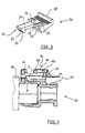
- FIG 3 shows the detailed configuration of the locking element 20, which on the first locking means 14 is arranged.
- the front portion 21 of the locking element 20 has a step, which is transverse to the connector direction extends. This is a first stage 22 and a second stage 23, this specially shaped front portion 21 at the one end of a tab 24th is arranged.
- This longitudinally extending tab 24 has the advantage that after the Inserting the locking element 20 and the corresponding choice of material, in particular made of plastic, a deflection of the front region 21 is possible.
- permanent fixing of the locking element 20 is a detent 25th provided, which causes the locking element 20 in a Endverrast ein remains when rough conditions on the connector, especially vibrations and temperature fluctuations.
- Grooves 26 of the Locking element 20 are provided to cover the plate of the first Locking means 14 engage around for the purpose of a longitudinal guide.
- a double guide is given, the one simple longitudinal displacement of the locking element 20 at the first locking means 14 causes.
- the locking element 20 has this at the other end of the tab 24th a handle portion 28 which is formed here, for example, as a cross bar.
- the shape of the Handle member 28 may in particular be selected so that a manual actuation of the Locking element 20 without auxiliary tools or optionally with auxiliary tools is possible.
- a particularly advantageous embodiment of the locking element 20, in particular of the handle part 28, can be seen in that after the production of the Clutch 10 and the locking element 20, the locking element 20 at his manufacturer in the Vorverrast ein (see Figure 2) is brought and a Such, even with cables and contact partners pre-assembled coupling 10 for further use. It is also conceivable, the clutch 10 according to Figure 2 prepare and to a Lucaskonfetechnischmaschine, this coupling 10 with cables and contact partners equipped to deliver. With respect to that shown in FIG Locking element 20 is still a starting from the tab 24 in the direction of Recesses 27 extending oblique guide 29 to mention the arranging the Locking element 20 is simplified to the first locking means 14.
- the locking element 20 is configured such that it at the locking means 14, more precisely on the plate, the is located on the housing 11, is guided.
- this is advantageous because it means one precise guidance of the locking element 20 when inserted with respect to the Clutch 10 (or alternatively the plug 30) is given.
- Such a leadership to the Locking means 14 may be present (as shown in Figure 3), but may alternatively also be omitted, so that the locking element 20 only with his Outside contours leader in the web assembly 15, 16, 17 is mounted. With that you can the grooves 26 and / or the oblique guide 29 of the locking element 20 (see FIG. omitted.
- a guide of the locking element 20 then takes place only either via the tab 24 and / or the outer surfaces of the handle portion 28 at the onset of Locking element 20 in the through the housing 11 and the web assembly 15, 16, 17 formed space.
- FIG 4 shows in section the coupling 10, wherein in the receiving space 18 now a corresponding connector 30 has been used, again here on the illustration the existing contact partner and cable has been omitted.
- the plug 30 has on its peripheral surface on the locking lug 31, which in the recess 141st can get.
- the insertion of the plug 30 and the presence of the latch 31 initially causes a primary lock by the locking lug 31 comes to rest with the corresponding surfaces of the recess 141 of the first locking means 14. thereof the front area 21 of the locking element 20, which remains at first, remains untouched still in its original position, as shown in Figure 2 is located. It Initially, only the primary locking between the coupling 10 and the plug 30 takes place by the locking lug 31 on the plug 30th
- transverse web arrangement 16 With regard to the transverse web arrangement 16 shown in FIG. 4, it is (contrary to FIG in FIGS. 1 and 6, only two are parallel mutually extending transverse webs 161, 162 which together form a recess 32.
- geometry and material of the cross bar 162 are selected so that when moving of the locking element 20 of the pre-locking position in the final locked position a short-term deformation (compliance) of the cross bar 162 is allowed when the Latch 25 is moved in the direction of the recess 32.
- FIG. 5 shows the section through the coupling 10 with inserted plug according to FIG. 4, wherein the locking element 20 from its Vorverrast ein shown in Figure 4 in its Endverrast ein (by longitudinal displacement in consideration of Figure 5 of right to left) has been brought.
- This longitudinal displacement of the locking element 20 causes the second stage 23 of the front portion 21 via the rising Latch 31 of the plug 30 causes an increase in the tab 24, so that the Front region 21 can enter into a recess 33 of the transverse web 17.
- This causes caused by the first locking means 14 primary lock will not be solved can, because the plate of the first locking means 14 in position by the front portion 21 of the Locking element 20 is fixed.
- Locking element 20 moved out of its Endverrast ein shown in Figure 5 provided that the locking element 20 has the locking lug 25, with the the locking element 20 on the coupling 10, in particular in the recess 32nd between the transverse webs 161, 162, can be fixed.
- the locking element 20 according to the invention its shape, his choice of materials and in particular its arrangement on the first locking means the Advantage that it readily retrofitted to the already existing first locking means can be, due to the shape and choice of materials without much effort brought from the Vorverrast ein in the Endverrast ein and due to the in Connection with the embodiment according to Figure 5 described positive connection in held this Endverrast ein.
- FIG. 6 finally shows the plug connection comprising coupling 10 and plug 30, wherein the plug 30 may also be a device plug.
- Locking element 20 the - as already described - extremely is effective and, moreover, still compact builds, as they do not over the longitudinal direction Outside dimensions of the housing of the clutch 10 protrudes.
- the locking element 20 according to the invention for any Couplings can be used, so the use the locking element is independent of the number of poles of the clutch or the Plug.
- the locking element is independent of the type of used Cable (eg round cable, flat cable or the like) and the contact partners used.
- the coupling 10 shown in FIG. 6 is also without the insert of the locking element 20 to use, in which case only one under certain Conditions sufficient primary lock (single lock) of the connector given is.
- FIG. 6 is an alternative conceivable embodiment of the crosspiece assembly 16, in turn, starting from the two approximately parallel extending webs 15 transverse thereto arranged transverse webs 161, 162 are present.
- this transverse web arrangement 16 shown in FIG. 6 is on the first crossbar 161, which is rigidly formed, a tab 163 arranged, the one has approximately square or rectangular course.
- This tab 163 forms together with the first crossbar 161, the recess 32, which later the locking lug 25th of the locking element 20 receives in its final locked position.
- FIG. 6 also shows the second transverse web 162 still a window 164, via which it is possible that the locking element 20 can be moved from the pre-locking position to the final locked position while the Latch 25 can get into the recess 32.
- Alternatives to this in FIG. 6 shown crosspiece assembly 16 are, for example, that the tab 163 not on the first crosspiece 161, but is arranged on the second crosspiece 162.
- there is not a tab 163 (such as shown in FIG approximately in U-shape) is arranged on the first crosspiece 161, but parallel between the two transverse webs 161, 162, a further crosspiece is present.
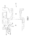
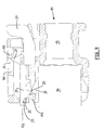
- FIGS. 7 to 9 show sections through the coupling 10, analogous to FIG Embodiment, as shown in Figure 2, as well as the function of the locking element 20 before and after insertion of the plug 30 into the coupling 10.
- the coupling 10 is shown, in which the locking element 20 (for example formed as shown in Figure 3, ie with guide means, or formed without means to its leadership on the locking means 14), wherein it can be seen that the locking element 20 is located with its front portion 21 in the recess 141.
- the locking element 20 for example formed as shown in Figure 3, ie with guide means, or formed without means to its leadership on the locking means 14
- the coupling 10 shown in Figure 7 with its locking element 20 shows So a preassembled state in which the front portion 21 of the locking element 20 lies in a first plane E1.
- Figure 8 shows that the plug 30 with its at least one latching nose 31 in the Clutch 10 has been used.
- the oblique design of the locking lug 31 causes when inserting the plug 30 into the coupling 10, that the front portion 21 of the Locking element 20 is raised in a further plane E2, without getting while the locking member 20 otherwise moved on.
- This increase in the Front portion 21 is effected by the second stage 23 via the slope of the Latch 31 can slide upwards until the position shown in Figure 8 is reached.
- the first stage 22 is at such a level on the crossbar 143 raised that this first step 22 is no longer applied to the crosspiece 143.
- the recess 33 is chosen so that the relevant part of the front area 21 can move freely there.
- FIG. 9 shows the end position of the locking element 20 on the coupling 10, which is achieved in that the locking element 20 from its position, the is further shifted to the left to those shown in Figure 9 To reach the final position.
- This shifting is made possible by the fact that the first Level 22 has been raised to such a level that they cross over the crosspiece 143 can slide.
- the locking element 20 takes a defined Vorverrast ein a (see Figure 7), from which it only in the Endverrast ein (see Figure 9) can be brought if the plug 30 correctly, that is completely in the clutch 10 has been used.
- the locking lug 31 would not be the deflection of the front area 21 from the first level E1 to the second level E2, so that the locking element 20 is not from its Vorverrast ein ( Figure 7) in his Endverrast ein ( Figure 9) can be brought.
- the invention equipped with the locking element coupling or analog a plug can be used for plug connections without limitation to the field of application this connector, wherein in a particularly advantageous manner an application in given the vehicle technology, since it is here above all on the permanent Connection between coupling and plug taking into account the conditions of use (Vibrations in the vehicle, strong temperature changes eg in the engine compartment of the Vehicle and the like) arrives.
Landscapes
- Details Of Connecting Devices For Male And Female Coupling (AREA)
Abstract
Description
- Figur 1
- dreidimensionale Ansicht einer Kupplung mit ersten Rastmitteln,
- Figur 2
- Schnitt durch eine Kupplung gemäß Figur 1 mit eingesetztem Verriegelungselement,
- Figur 3
- Detailansicht eines Verriegelungselementes,
- Figur 4
- Schnitt durch eine Kupplung gemäß Figur 1 mit eingesetztem Stecker und Verriegelungselement in seiner Vorverraststellung,
- Figur 5
- Schnitt durch eine Steckverbindung gemäß Figur 4, wobei sich das Verriegelungselement in seiner Endverraststellung befindet,
- Figur 6
- dreidimensionale Ansicht einer Steckverbindung mit Doppelverriegelung mittels Verriegelungselement,
- Figur 7 bis 9
- Schnitte durch eine Kupplung analog zu Figur 2 und die Funktion des Verriegelungslements vor und nach dem Einsetzen des Steckers.
- 10
- Kupplung
- 11
- Gehäuse
- 12
- Schutzkragen
- 13
- Aufnahmeraum
- 14
- Rastmittel
- 15
- Steg
- 16
- Quersteganordnung
- 17
- Quersteganordnung
- 18
- Aufnahmeraum
- 19 20
- Verriegelungselement
- 21
- Frontbereich
- 22
- erste Stufe
- 23
- zweite Stufe
- 24
- Lasche
- 25
- Rastnase
- 26
- Nuten
- 27
- Ausnehmungen
- 28
- Griffteil
- 29
- Schrägführung
- 30
- Stecker
- 31
- Rastnase
- 32
- Ausnehmung
- 33
- Ausnehmung
- 141
- Ausnehmung
- 142
- Anschlagfläche
- 143
- Quersteg
- 161
- erster Quersteg
- 162
- zweiter Quersteg
- 163
- Lasche
- 164
- Fenster
Claims (7)
- Kupplung (10) oder Stecker (30) einer Steckverbindung, wobei die Kupplung (10) oder der Stecker (30) erste Rastmittel (14) aufweist, mittels derer bei zusammengesetzter Steckverbindung eine erste Verrastung (Primärverriegelung) zwischen Kupplung (10) und Stecker (30) erfolgt und wobei die Kupplung (10) oder der Stecker (30) ein Verriegelungselement (20) aufweist, welches auf die Kupplung (10) oder den Stecker (30) aufsetzbar und zwischen einer Vorverraststellung und einer Endverraststellung in Steckrichtung längs verschiebbar ist, wobei das Verriegelungselement (20) derart gestaltet ist, dass es erst dann in die Endverraststellung verschiebbar ist, wenn sich der Stecker (30) vollständig in der Kupplung (10) befindet (oder umgekehrt), dadurch gekennzeichnet, dass das Verriegelungselement (20) an den ersten Rastmitteln (14) angeordnet ist.
- Kupplung (10) oder Stecker (30) nach Anspruch 1, dadurch gekennzeichnet, dass das Verriegelungselement (20) ausgehend von einem Griffteil (28) eine Lasche (24) mit einem zweigestuften Frontbereich (21) aufweist.
- Kupplung (10) oder Stecker (30) nach Anspruch 1 oder 2, dadurch gekennzeichnet, dass die ersten Rastmittel (14) als Platte ausgebildet sind, wobei die Platte über einen Steg mit einem Gehäuse (11) der Kupplung (10) oder des Steckers (30) verbunden ist.
- Kupplung (10) oder Stecker (30) nach Anspruch 3, dadurch gekennzeichnet, dass das Verriegelungselement (20) Nuten (26) aufweist, die die Platte umgreifen und eine Führung des Verriegelungselementes (20) bewirken.
- Kupplung (10) oder Stecker (30) nach Anspruch 3 oder 4, dadurch gekennzeichnet, dass die Platte Stege aufweist, wobei die Stege mit Ausnehmungen (27) des Verriegelungselementes (20) zwecks dessen Führung korrespondieren.
- Kupplung (10) oder Stecker (30) nach einem der vorhergehenden Ansprüche, dadurch gekennzeichnet, dass das Verriegelungselement (20) eine Rastnase (25) aufweist, mit dem das Verriegelungselement (20) an der Kupplung (10) oder dem Stecker (30) festlegbar ist.
- Kupplung (10) oder Stecker (30) nach einem der vorhergehenden Ansprüche, dadurch gekennzeichnet, dass das Verriegelungselement (20) keine Mittel zu seiner Führung an den Rastmitteln (14), insbesondere an der Platte, aufweist.
Applications Claiming Priority (2)
| Application Number | Priority Date | Filing Date | Title |
|---|---|---|---|
| DE10341136 | 2003-09-06 | ||
| DE2003141136 DE10341136A1 (de) | 2003-09-06 | 2003-09-06 | Verriegelungselement für eine Steckverbindung |
Publications (3)
| Publication Number | Publication Date |
|---|---|
| EP1513225A2 true EP1513225A2 (de) | 2005-03-09 |
| EP1513225A3 EP1513225A3 (de) | 2009-11-04 |
| EP1513225B1 EP1513225B1 (de) | 2018-05-02 |
Family
ID=34129674
Family Applications (1)
| Application Number | Title | Priority Date | Filing Date |
|---|---|---|---|
| EP04021124.5A Expired - Lifetime EP1513225B1 (de) | 2003-09-06 | 2004-09-06 | Verriegelungselement für eine Steckverbindung |
Country Status (3)
| Country | Link |
|---|---|
| EP (1) | EP1513225B1 (de) |
| DE (1) | DE10341136A1 (de) |
| ES (1) | ES2676504T3 (de) |
Cited By (5)
| Publication number | Priority date | Publication date | Assignee | Title |
|---|---|---|---|---|
| EP1936755A1 (de) * | 2006-12-20 | 2008-06-25 | Hirschmann Automotive GmbH | Steckverbindung, bestehend aus einem Stecker sowie einem Kuppler mit einem Kontaktträger und einem Schutzkragen |
| WO2009026149A1 (en) * | 2007-08-17 | 2009-02-26 | Panduit Corp. | Plug locking assembly |
| WO2016087579A1 (de) * | 2014-12-03 | 2016-06-09 | Hirschmann Automotive Gmbh | Steckverbindung mit verbessertem verriegelungselement |
| CN106099480A (zh) * | 2016-08-14 | 2016-11-09 | 华威博奥电力设备有限公司 | 可调式插拔模块 |
| EP2831959B1 (de) * | 2012-03-28 | 2018-12-19 | TE Connectivity Corporation | Elektrische verbinderanordnung mit einem elektrischen verbinder mit verbinderpositionsbestätigungsvorrichtung |
Families Citing this family (6)
| Publication number | Priority date | Publication date | Assignee | Title |
|---|---|---|---|---|
| DE102004049333B4 (de) * | 2004-10-09 | 2007-03-08 | Hirschmann Automotive Gmbh | Steckverbinder zur Anwendung in Fahrzeugen |
| DE102005019261A1 (de) * | 2005-04-26 | 2006-11-09 | Kostal Kontakt Systeme Gmbh | Elektrischer Steckverbinder für ein Kraftfahrzeug |
| DE102008030339A1 (de) | 2008-06-30 | 2009-12-31 | Continental Automotive Gmbh | Hochvolt-Steckverbindung für Kraftfahrzeuge |
| DE102009035729A1 (de) | 2009-08-01 | 2010-03-25 | Daimler Ag | Kontaktiersystem und Verfahren zur Montage desselben |
| DE102014221041A1 (de) | 2013-10-16 | 2015-04-16 | Hirschmann Automotive Gmbh | Steckverbindung mit einem Verriegelungselement mit Flügeln |
| DE202021102260U1 (de) | 2021-04-28 | 2022-07-29 | Fep Fahrzeugelektrik Pirna Gmbh & Co. Kg | Sensor und mit dem Sensor koppelbarer Anschlussstecker |
Family Cites Families (12)
| Publication number | Priority date | Publication date | Assignee | Title |
|---|---|---|---|---|
| US4915643A (en) * | 1987-10-28 | 1990-04-10 | Yazaki Corporation | Connector |
| US5120255A (en) * | 1990-03-01 | 1992-06-09 | Yazaki Corporation | Complete locking confirming device for confirming the complete locking of an electric connector |
| EP0655807A3 (de) * | 1993-11-30 | 1995-12-13 | Whitaker Corp | Vorrichtung zur Lagesicherung eines Verbinders. |
| JP2921645B2 (ja) * | 1994-07-12 | 1999-07-19 | 矢崎総業株式会社 | コネクタ嵌合検知構造 |
| US5681178A (en) * | 1995-06-27 | 1997-10-28 | The Whitaker Corporation | Electrical connector with connector position assurance device |
| EP0757411A3 (de) * | 1995-08-03 | 1997-10-15 | Sumitomo Wiring Systems | Verbinder |
| JP3228854B2 (ja) * | 1995-09-21 | 2001-11-12 | 矢崎総業株式会社 | 電気コネクタ |
| JPH09219255A (ja) * | 1996-02-07 | 1997-08-19 | Yazaki Corp | 二重ロックコネクタ |
| US5807130A (en) * | 1996-05-31 | 1998-09-15 | Chrysler Corporation | Two way electrical connector |
| JPH10199622A (ja) * | 1997-01-16 | 1998-07-31 | Yazaki Corp | コネクタ用二重ロック |
| US6354860B1 (en) * | 1999-11-01 | 2002-03-12 | Osram Sylvania Inc. | Connector and connector assembly |
| JP3976134B2 (ja) * | 2001-09-05 | 2007-09-12 | 矢崎総業株式会社 | 半嵌合防止コネクタ |
-
2003
- 2003-09-06 DE DE2003141136 patent/DE10341136A1/de not_active Ceased
-
2004
- 2004-09-06 EP EP04021124.5A patent/EP1513225B1/de not_active Expired - Lifetime
- 2004-09-06 ES ES04021124.5T patent/ES2676504T3/es not_active Expired - Lifetime
Cited By (7)
| Publication number | Priority date | Publication date | Assignee | Title |
|---|---|---|---|---|
| EP1936755A1 (de) * | 2006-12-20 | 2008-06-25 | Hirschmann Automotive GmbH | Steckverbindung, bestehend aus einem Stecker sowie einem Kuppler mit einem Kontaktträger und einem Schutzkragen |
| WO2009026149A1 (en) * | 2007-08-17 | 2009-02-26 | Panduit Corp. | Plug locking assembly |
| US7632125B2 (en) | 2007-08-17 | 2009-12-15 | Panduit Corp. | Plug locking assembly |
| EP2831959B1 (de) * | 2012-03-28 | 2018-12-19 | TE Connectivity Corporation | Elektrische verbinderanordnung mit einem elektrischen verbinder mit verbinderpositionsbestätigungsvorrichtung |
| WO2016087579A1 (de) * | 2014-12-03 | 2016-06-09 | Hirschmann Automotive Gmbh | Steckverbindung mit verbessertem verriegelungselement |
| US10193273B2 (en) | 2014-12-03 | 2019-01-29 | Hirschmann Automotive Gmbh | Plug-in connection having a locking element |
| CN106099480A (zh) * | 2016-08-14 | 2016-11-09 | 华威博奥电力设备有限公司 | 可调式插拔模块 |
Also Published As
| Publication number | Publication date |
|---|---|
| EP1513225A3 (de) | 2009-11-04 |
| DE10341136A1 (de) | 2005-04-07 |
| EP1513225B1 (de) | 2018-05-02 |
| ES2676504T3 (es) | 2018-07-20 |
Similar Documents
| Publication | Publication Date | Title |
|---|---|---|
| EP1449280B1 (de) | Steckverbinder mit während des steckvorgangs verrastender sekundärverriegelung | |
| DE69707614T2 (de) | Elektrischer Steckverbinder | |
| EP3679631B1 (de) | Steckverbinder mit verriegelungshaken zur festlegung seines kontaktträgers in seinem aussengehäuse | |
| EP2287974A1 (de) | Elektrischer Push-Pull-Steckverbinder | |
| EP1513225B1 (de) | Verriegelungselement für eine Steckverbindung | |
| DE69806239T2 (de) | Verbinder mit sekondärverriegelung und kupplungsvorrichtung | |
| DE102004053538A1 (de) | Kupplungsvorrichtung zum Verbinden von Leitungen und Kraftfahrzeug mit einer derartigen Kupplungsvorrichtung | |
| DE102009053695A1 (de) | Anschlussvorrichtung | |
| DE102020204825A1 (de) | Verbindungseinheit zur Verbindung von Fluidleitungen | |
| EP0984524B1 (de) | Zweiteiliger elektrischer Steckverbinder mit einem Koppelteil und einem bewegbaren Kontrollelement | |
| EP1936755B1 (de) | Steckverbindung, bestehend aus einem Stecker sowie einem Kuppler mit einem Kontaktträger und einem Schutzkragen | |
| DE102008059827A1 (de) | Gleitschuh für ein Schaltelement einer Schalteinrichtung und Schaltelement mit einem solchen Gleitschuh | |
| DE102004016599B3 (de) | Steckverbindung mit Winkelarretierung | |
| WO2007020020A1 (de) | Elektrischer steckverbinder | |
| DE60034626T2 (de) | Verbinder mit Verhinderung einer unvollständigen Kupplung | |
| EP2713450B1 (de) | Steckverbindung und Verfahren zum Betreiben einer solchen Steckverbindung | |
| DE2237946B2 (de) | Huelse fuer schreib- und aehnliche geraete | |
| DE69500802T2 (de) | Anschlusselementsverriegelung mit Gitterstruktur für einen Steckverbinder | |
| DE10326834B4 (de) | Steckverbinder | |
| EP0208887B1 (de) | Rohrverbindung | |
| DE19848264C1 (de) | Kopplungseinrichtung | |
| DE1765099B2 (de) | Elektrische steckvorrichtung | |
| EP1813000B1 (de) | Geschlossenes gehäuse für ein verriegelungselement einer steckverbindung | |
| EP2587595B1 (de) | Steckverbindung und Verfahren zum Betreiben einer Steckverbindung für Hochvolt-Anwendungen | |
| DE102013110512B4 (de) | Steckverbinder mit Primär- und Sekundärverriegelung |
Legal Events
| Date | Code | Title | Description |
|---|---|---|---|
| PUAI | Public reference made under article 153(3) epc to a published international application that has entered the european phase |
Free format text: ORIGINAL CODE: 0009012 |
|
| AK | Designated contracting states |
Kind code of ref document: A2 Designated state(s): AT BE BG CH CY CZ DE DK EE ES FI FR GB GR HU IE IT LI LU MC NL PL PT RO SE SI SK TR |
|
| AX | Request for extension of the european patent |
Extension state: AL HR LT LV MK |
|
| PUAL | Search report despatched |
Free format text: ORIGINAL CODE: 0009013 |
|
| AK | Designated contracting states |
Kind code of ref document: A3 Designated state(s): AT BE BG CH CY CZ DE DK EE ES FI FR GB GR HU IE IT LI LU MC NL PL PT RO SE SI SK TR |
|
| AX | Request for extension of the european patent |
Extension state: AL HR LT LV MK |
|
| 17P | Request for examination filed |
Effective date: 20100301 |
|
| AKX | Designation fees paid |
Designated state(s): AT BE BG CH CY CZ DE DK EE ES FI FR GB GR HU IE IT LI LU MC NL PL PT RO SE SI SK TR |
|
| 17Q | First examination report despatched |
Effective date: 20100902 |
|
| STAA | Information on the status of an ep patent application or granted ep patent |
Free format text: STATUS: EXAMINATION IS IN PROGRESS |
|
| REG | Reference to a national code |
Ref country code: DE Ref legal event code: R079 Ref document number: 502004015676 Country of ref document: DE Free format text: PREVIOUS MAIN CLASS: H01R0004180000 Ipc: H01R0013639000 |
|
| GRAP | Despatch of communication of intention to grant a patent |
Free format text: ORIGINAL CODE: EPIDOSNIGR1 |
|
| STAA | Information on the status of an ep patent application or granted ep patent |
Free format text: STATUS: GRANT OF PATENT IS INTENDED |
|
| RIC1 | Information provided on ipc code assigned before grant |
Ipc: H01R 13/627 20060101ALI20171109BHEP Ipc: H01R 13/639 20060101AFI20171109BHEP Ipc: H01R 43/26 20060101ALN20171109BHEP Ipc: H01R 13/641 20060101ALI20171109BHEP |
|
| INTG | Intention to grant announced |
Effective date: 20171213 |
|
| GRAS | Grant fee paid |
Free format text: ORIGINAL CODE: EPIDOSNIGR3 |
|
| GRAA | (expected) grant |
Free format text: ORIGINAL CODE: 0009210 |
|
| STAA | Information on the status of an ep patent application or granted ep patent |
Free format text: STATUS: THE PATENT HAS BEEN GRANTED |
|
| AK | Designated contracting states |
Kind code of ref document: B1 Designated state(s): AT BE BG CH CY CZ DE DK EE ES FI FR GB GR HU IE IT LI LU MC NL PL PT RO SE SI SK TR |
|
| REG | Reference to a national code |
Ref country code: GB Ref legal event code: FG4D Free format text: NOT ENGLISH |
|
| REG | Reference to a national code |
Ref country code: CH Ref legal event code: EP Ref country code: AT Ref legal event code: REF Ref document number: 996250 Country of ref document: AT Kind code of ref document: T Effective date: 20180515 |
|
| REG | Reference to a national code |
Ref country code: DE Ref legal event code: R096 Ref document number: 502004015676 Country of ref document: DE Ref country code: IE Ref legal event code: FG4D Free format text: LANGUAGE OF EP DOCUMENT: GERMAN |
|
| REG | Reference to a national code |
Ref country code: RO Ref legal event code: EPE |
|
| REG | Reference to a national code |
Ref country code: ES Ref legal event code: FG2A Ref document number: 2676504 Country of ref document: ES Kind code of ref document: T3 Effective date: 20180720 |
|
| REG | Reference to a national code |
Ref country code: NL Ref legal event code: MP Effective date: 20180502 |
|
| REG | Reference to a national code |
Ref country code: FR Ref legal event code: PLFP Year of fee payment: 15 |
|
| PG25 | Lapsed in a contracting state [announced via postgrant information from national office to epo] |
Ref country code: SE Free format text: LAPSE BECAUSE OF FAILURE TO SUBMIT A TRANSLATION OF THE DESCRIPTION OR TO PAY THE FEE WITHIN THE PRESCRIBED TIME-LIMIT Effective date: 20180502 Ref country code: BG Free format text: LAPSE BECAUSE OF FAILURE TO SUBMIT A TRANSLATION OF THE DESCRIPTION OR TO PAY THE FEE WITHIN THE PRESCRIBED TIME-LIMIT Effective date: 20180802 Ref country code: FI Free format text: LAPSE BECAUSE OF FAILURE TO SUBMIT A TRANSLATION OF THE DESCRIPTION OR TO PAY THE FEE WITHIN THE PRESCRIBED TIME-LIMIT Effective date: 20180502 |
|
| PG25 | Lapsed in a contracting state [announced via postgrant information from national office to epo] |
Ref country code: GR Free format text: LAPSE BECAUSE OF FAILURE TO SUBMIT A TRANSLATION OF THE DESCRIPTION OR TO PAY THE FEE WITHIN THE PRESCRIBED TIME-LIMIT Effective date: 20180803 Ref country code: NL Free format text: LAPSE BECAUSE OF FAILURE TO SUBMIT A TRANSLATION OF THE DESCRIPTION OR TO PAY THE FEE WITHIN THE PRESCRIBED TIME-LIMIT Effective date: 20180502 |
|
| PG25 | Lapsed in a contracting state [announced via postgrant information from national office to epo] |
Ref country code: PT Free format text: LAPSE BECAUSE OF FAILURE TO SUBMIT A TRANSLATION OF THE DESCRIPTION OR TO PAY THE FEE WITHIN THE PRESCRIBED TIME-LIMIT Effective date: 20180903 |
|
| PG25 | Lapsed in a contracting state [announced via postgrant information from national office to epo] |
Ref country code: PL Free format text: LAPSE BECAUSE OF FAILURE TO SUBMIT A TRANSLATION OF THE DESCRIPTION OR TO PAY THE FEE WITHIN THE PRESCRIBED TIME-LIMIT Effective date: 20180502 Ref country code: SK Free format text: LAPSE BECAUSE OF FAILURE TO SUBMIT A TRANSLATION OF THE DESCRIPTION OR TO PAY THE FEE WITHIN THE PRESCRIBED TIME-LIMIT Effective date: 20180502 Ref country code: DK Free format text: LAPSE BECAUSE OF FAILURE TO SUBMIT A TRANSLATION OF THE DESCRIPTION OR TO PAY THE FEE WITHIN THE PRESCRIBED TIME-LIMIT Effective date: 20180502 Ref country code: EE Free format text: LAPSE BECAUSE OF FAILURE TO SUBMIT A TRANSLATION OF THE DESCRIPTION OR TO PAY THE FEE WITHIN THE PRESCRIBED TIME-LIMIT Effective date: 20180502 |
|
| REG | Reference to a national code |
Ref country code: DE Ref legal event code: R097 Ref document number: 502004015676 Country of ref document: DE |
|
| PLBE | No opposition filed within time limit |
Free format text: ORIGINAL CODE: 0009261 |
|
| STAA | Information on the status of an ep patent application or granted ep patent |
Free format text: STATUS: NO OPPOSITION FILED WITHIN TIME LIMIT |
|
| 26N | No opposition filed |
Effective date: 20190205 |
|
| PG25 | Lapsed in a contracting state [announced via postgrant information from national office to epo] |
Ref country code: MC Free format text: LAPSE BECAUSE OF FAILURE TO SUBMIT A TRANSLATION OF THE DESCRIPTION OR TO PAY THE FEE WITHIN THE PRESCRIBED TIME-LIMIT Effective date: 20180502 |
|
| REG | Reference to a national code |
Ref country code: CH Ref legal event code: PL |
|
| PG25 | Lapsed in a contracting state [announced via postgrant information from national office to epo] |
Ref country code: SI Free format text: LAPSE BECAUSE OF FAILURE TO SUBMIT A TRANSLATION OF THE DESCRIPTION OR TO PAY THE FEE WITHIN THE PRESCRIBED TIME-LIMIT Effective date: 20180502 |
|
| REG | Reference to a national code |
Ref country code: BE Ref legal event code: MM Effective date: 20180930 |
|
| REG | Reference to a national code |
Ref country code: IE Ref legal event code: MM4A |
|
| PG25 | Lapsed in a contracting state [announced via postgrant information from national office to epo] |
Ref country code: LU Free format text: LAPSE BECAUSE OF NON-PAYMENT OF DUE FEES Effective date: 20180906 |
|
| PG25 | Lapsed in a contracting state [announced via postgrant information from national office to epo] |
Ref country code: IE Free format text: LAPSE BECAUSE OF NON-PAYMENT OF DUE FEES Effective date: 20180906 |
|
| PG25 | Lapsed in a contracting state [announced via postgrant information from national office to epo] |
Ref country code: LI Free format text: LAPSE BECAUSE OF NON-PAYMENT OF DUE FEES Effective date: 20180930 Ref country code: BE Free format text: LAPSE BECAUSE OF NON-PAYMENT OF DUE FEES Effective date: 20180930 Ref country code: CH Free format text: LAPSE BECAUSE OF NON-PAYMENT OF DUE FEES Effective date: 20180930 |
|
| REG | Reference to a national code |
Ref country code: AT Ref legal event code: MM01 Ref document number: 996250 Country of ref document: AT Kind code of ref document: T Effective date: 20180906 |
|
| PG25 | Lapsed in a contracting state [announced via postgrant information from national office to epo] |
Ref country code: AT Free format text: LAPSE BECAUSE OF NON-PAYMENT OF DUE FEES Effective date: 20180906 |
|
| PG25 | Lapsed in a contracting state [announced via postgrant information from national office to epo] |
Ref country code: TR Free format text: LAPSE BECAUSE OF FAILURE TO SUBMIT A TRANSLATION OF THE DESCRIPTION OR TO PAY THE FEE WITHIN THE PRESCRIBED TIME-LIMIT Effective date: 20180502 |
|
| PG25 | Lapsed in a contracting state [announced via postgrant information from national office to epo] |
Ref country code: HU Free format text: LAPSE BECAUSE OF FAILURE TO SUBMIT A TRANSLATION OF THE DESCRIPTION OR TO PAY THE FEE WITHIN THE PRESCRIBED TIME-LIMIT; INVALID AB INITIO Effective date: 20040906 |
|
| PG25 | Lapsed in a contracting state [announced via postgrant information from national office to epo] |
Ref country code: CY Free format text: LAPSE BECAUSE OF FAILURE TO SUBMIT A TRANSLATION OF THE DESCRIPTION OR TO PAY THE FEE WITHIN THE PRESCRIBED TIME-LIMIT Effective date: 20180502 |
|
| PGFP | Annual fee paid to national office [announced via postgrant information from national office to epo] |
Ref country code: RO Payment date: 20230824 Year of fee payment: 20 Ref country code: GB Payment date: 20230920 Year of fee payment: 20 Ref country code: CZ Payment date: 20230828 Year of fee payment: 20 |
|
| PGFP | Annual fee paid to national office [announced via postgrant information from national office to epo] |
Ref country code: FR Payment date: 20230927 Year of fee payment: 20 Ref country code: DE Payment date: 20230920 Year of fee payment: 20 |
|
| PGFP | Annual fee paid to national office [announced via postgrant information from national office to epo] |
Ref country code: ES Payment date: 20231123 Year of fee payment: 20 |
|
| PGFP | Annual fee paid to national office [announced via postgrant information from national office to epo] |
Ref country code: IT Payment date: 20230927 Year of fee payment: 20 |
|
| REG | Reference to a national code |
Ref country code: DE Ref legal event code: R071 Ref document number: 502004015676 Country of ref document: DE |
|
| REG | Reference to a national code |
Ref country code: GB Ref legal event code: PE20 Expiry date: 20240905 |
|
| REG | Reference to a national code |
Ref country code: ES Ref legal event code: FD2A Effective date: 20240927 |
|
| PG25 | Lapsed in a contracting state [announced via postgrant information from national office to epo] |
Ref country code: GB Free format text: LAPSE BECAUSE OF EXPIRATION OF PROTECTION Effective date: 20240905 |
|
| PG25 | Lapsed in a contracting state [announced via postgrant information from national office to epo] |
Ref country code: ES Free format text: LAPSE BECAUSE OF EXPIRATION OF PROTECTION Effective date: 20240907 |
|
| PG25 | Lapsed in a contracting state [announced via postgrant information from national office to epo] |
Ref country code: CZ Free format text: LAPSE BECAUSE OF EXPIRATION OF PROTECTION Effective date: 20240906 |
|
| PG25 | Lapsed in a contracting state [announced via postgrant information from national office to epo] |
Ref country code: GB Free format text: LAPSE BECAUSE OF EXPIRATION OF PROTECTION Effective date: 20240905 Ref country code: ES Free format text: LAPSE BECAUSE OF EXPIRATION OF PROTECTION Effective date: 20240907 Ref country code: CZ Free format text: LAPSE BECAUSE OF EXPIRATION OF PROTECTION Effective date: 20240906 |