EP1513178A2 - Kontaktanordnung für strombegrenzende Schutzschalter - Google Patents
Kontaktanordnung für strombegrenzende Schutzschalter Download PDFInfo
- Publication number
- EP1513178A2 EP1513178A2 EP04103886A EP04103886A EP1513178A2 EP 1513178 A2 EP1513178 A2 EP 1513178A2 EP 04103886 A EP04103886 A EP 04103886A EP 04103886 A EP04103886 A EP 04103886A EP 1513178 A2 EP1513178 A2 EP 1513178A2
- Authority
- EP
- European Patent Office
- Prior art keywords
- contact
- spring
- contact arrangement
- contact bridge
- arrangement according
- Prior art date
- Legal status (The legal status is an assumption and is not a legal conclusion. Google has not performed a legal analysis and makes no representation as to the accuracy of the status listed.)
- Withdrawn
Links
Images
Classifications
-
- H—ELECTRICITY
- H01—ELECTRIC ELEMENTS
- H01H—ELECTRIC SWITCHES; RELAYS; SELECTORS; EMERGENCY PROTECTIVE DEVICES
- H01H1/00—Contacts
- H01H1/12—Contacts characterised by the manner in which co-operating contacts engage
- H01H1/14—Contacts characterised by the manner in which co-operating contacts engage by abutting
- H01H1/20—Bridging contacts
- H01H1/2041—Rotating bridge
- H01H1/205—Details concerning the elastic mounting of the rotating bridge in the rotor
-
- H—ELECTRICITY
- H01—ELECTRIC ELEMENTS
- H01H—ELECTRIC SWITCHES; RELAYS; SELECTORS; EMERGENCY PROTECTIVE DEVICES
- H01H73/00—Protective overload circuit-breaking switches in which excess current opens the contacts by automatic release of mechanical energy stored by previous operation of a hand reset mechanism
- H01H73/02—Details
- H01H73/04—Contacts
- H01H73/045—Bridging contacts
-
- H—ELECTRICITY
- H01—ELECTRIC ELEMENTS
- H01H—ELECTRIC SWITCHES; RELAYS; SELECTORS; EMERGENCY PROTECTIVE DEVICES
- H01H77/00—Protective overload circuit-breaking switches operated by excess current and requiring separate action for resetting
- H01H77/02—Protective overload circuit-breaking switches operated by excess current and requiring separate action for resetting in which the excess current itself provides the energy for opening the contacts, and having a separate reset mechanism
- H01H77/10—Protective overload circuit-breaking switches operated by excess current and requiring separate action for resetting in which the excess current itself provides the energy for opening the contacts, and having a separate reset mechanism with electrodynamic opening
- H01H77/102—Protective overload circuit-breaking switches operated by excess current and requiring separate action for resetting in which the excess current itself provides the energy for opening the contacts, and having a separate reset mechanism with electrodynamic opening characterised by special mounting of contact arm, allowing blow-off movement
- H01H77/104—Protective overload circuit-breaking switches operated by excess current and requiring separate action for resetting in which the excess current itself provides the energy for opening the contacts, and having a separate reset mechanism with electrodynamic opening characterised by special mounting of contact arm, allowing blow-off movement with a stable blow-off position
-
- H—ELECTRICITY
- H01—ELECTRIC ELEMENTS
- H01H—ELECTRIC SWITCHES; RELAYS; SELECTORS; EMERGENCY PROTECTIVE DEVICES
- H01H1/00—Contacts
- H01H1/12—Contacts characterised by the manner in which co-operating contacts engage
- H01H1/14—Contacts characterised by the manner in which co-operating contacts engage by abutting
- H01H1/20—Bridging contacts
- H01H1/2041—Rotating bridge
- H01H1/2058—Rotating bridge being assembled in a cassette, which can be placed as a complete unit into a circuit breaker
-
- H—ELECTRICITY
- H01—ELECTRIC ELEMENTS
- H01H—ELECTRIC SWITCHES; RELAYS; SELECTORS; EMERGENCY PROTECTIVE DEVICES
- H01H1/00—Contacts
- H01H1/12—Contacts characterised by the manner in which co-operating contacts engage
- H01H1/14—Contacts characterised by the manner in which co-operating contacts engage by abutting
- H01H1/22—Contacts characterised by the manner in which co-operating contacts engage by abutting with rigid pivoted member carrying the moving contact
- H01H1/221—Contacts characterised by the manner in which co-operating contacts engage by abutting with rigid pivoted member carrying the moving contact and a contact pressure spring acting between the pivoted member and a supporting member
- H01H2001/223—Contacts characterised by the manner in which co-operating contacts engage by abutting with rigid pivoted member carrying the moving contact and a contact pressure spring acting between the pivoted member and a supporting member using a torsion spring
Definitions
- the invention relates to a contact arrangement for current-limiting circuit breaker in Low-voltage range according to the preamble of claim 1, in particular for current-limiting circuit breakers.
- From DE 101 50 550 C1 is a contact arrangement for current-limiting circuit breakers known in which a double interrupting rotary contact bridge over four contact pressure tension springs arranged in pairs symmetrically on both sides of the contact bridge is connected to a switching shaft.
- a double interrupting rotary contact bridge over four contact pressure tension springs arranged in pairs symmetrically on both sides of the contact bridge is connected to a switching shaft.
- the one-piece pairs of tension springs store with their connecting pieces in notches of the contact bridge and with the extensions equipped ends via steel pins in notches of the shift shaft. To guarantee safe movements of the contact bridge this is provided with a slot, by the one in the transverse axis of the shift shaft extending fixed bearing axis is guided. Due to the polweise composition of the switching shafts Polweise associated switching shaft segments is the contact arrangement for modular Compatible circuit breaker suitable. The disadvantage is the complicated trained and thus expensive as well as expensive to mount tension spring pairs.
- the object of the invention therefore consists in a technologically improved current-limiting Contact arrangement with retained electro-dynamic contact opening.
- the locking cams are mounted longitudinally displaceable and provided with convex top surfaces.
- the second spring ends of the torsion springs slide over the convex Head surfaces and move the locking cams against their cam springs.
- the Electrodynamically acted contact bridge is initially an increasing Spring force opposite. If the second spring ends, however, the Can overcome the apex line or apex of the convex head surfaces the locking cams come back through the action of their cam springs in the direction of their Move back starting position.
- the decreasing counterforce causes the Contact bridge in a stable repulsion position passes, from which they only at the final Opening the contact arrangement is released as a result of triggering protective organs.
- Round curved second spring ends and provided for this in the locking cams Sliding grooves are advantageous for safe operation of the contact arrangement.
- recessed damping elements - for example, made of elastic Material - serve to capture the kinetic energy of the electrodynamically accelerated Contact bridge.
- the half-wave polweise consists of two halves, store in the insulating housing and between those of the bearing pin with the on it playful - usually via a slot - overlapping rotary contact bridge is held.
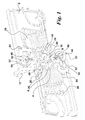
- the contact arrangement is made of an insulating housing consisting of two half-shells 2, from which in Fig. 1, 2 and 4, the front half-shell is removed.
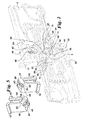
- circular recesses 4 of the insulating housing 2 are two, forming a switching shaft Shift shaft halves 6 and 8 are mounted, of which in Figs. 2 and 4, the front Shift shaft half 6 and in Fig. 3 both switching shaft halves are removed.
- the shift shaft 6, 8 has outwardly facing driving pins 10, in which to an actuating mechanism leading actuating levers 12 engage.
- a metallic bearing pin 14 is held.
- the contact bridge 16 extends in the median plane of the Wegpols, which coincides with the parting plane of the insulating housing 2.
- the rotation axis 22 of the contact assembly falls into the bearing pin 14.
- At the ends of the contact arms 18 are diametrically opposed contacts 24 fixed, which in the in Fig. 1, 2, 3 and 4a shown switching position of the contact arrangement with the outside guided fixed contacts 26 are connected. Between the half-shells of Insulating housing 2 arc quenching plates 28 are fixed.
- On both sides of the contact bridge 16 are above the bearing pin 14 insulating bushes 34 on which the spring coils 36 of the torsion springs 30th and store 32 loosely.
- the insulating bushes 34 through the switching shaft halves 6 hidden and omitted in Fig. 3.
- the torsion spring 30 or 32 is connected to a first Spring end 38 mounted in each case one of the contact arms 18 and supports itself with a second spring end 40 against the top surface 42 of a hat-shaped latching cam 44 and 46, respectively.
- the locking cams 44 and 46 shown individually in FIG. 5 are mounted longitudinally displaceable in the insulating housing 2.
- Cam springs designed as compression springs 48 are supported on the one hand by the inside of the top surfaces 42 and on the other against inserted in the insulating housing 2 abutment 50 from.
- At the foot of the Locking cams 44 and 46 are formed outwardly bulges 52, with the in Insulated housing 2 trained stops 54 cooperate by the locking cams 44 and 46 by the force of the cam springs 48 in the figures 1 to Assume 4 starting position.
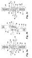
- FIG. 3 are as essential details of the contact arrangement according to the invention again the contact bridge 16, the torsion springs 30 and 32 and the locking cams 44 and 46 are shown.
- FIG. 3a is a front view
- FIG. 3b shows a representation from the left
- FIG. 3c shows a representation from the rear.
- the second spring ends 40 are bent around, wherein the bending axis parallel to the axis of rotation 22nd runs.
- the arcuate second spring ends 40 are in a sliding groove 62 of the Head surfaces 42 out (Fig. 5).
- the top surfaces 42 have two in a blunt Angle merging bevels 58 and 60, which are parallel to the axis of rotation 22 extend.
- the second take Spring ends 40 enter a first stable position by referring to those indicated in Fig. 3a Oblique 58 of the latching cam located in its initial position 44 and 46 create.
- the torsion springs 30 and 32 cause their first spring ends 38 the required contact pressure, with their second spring ends 40 against support the slopes 58.
- the angle of attack of the bevels 58 and the ratio of Spring forces between the torsion springs 38, 40 and the cam springs 48 is through customary dimensioning set so that the locking cams 44, 46 in the closed position not be displaced from their starting position.
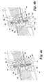
- two cylindrical damping elements 64 are further provided, to those in the event of a short circuit to restrict movement and absorb movement of kinetic energy the contact bridge 16 whose contact arms 18 strike.
- the contact bridge 16 In order to the risk of rebound of the contact bridge 16 in the closed position as a result of very high kinetic energy when strong short-circuit currents occur avoided.
Landscapes
- Physics & Mathematics (AREA)
- Electromagnetism (AREA)
- Driving Mechanisms And Operating Circuits Of Arc-Extinguishing High-Tension Switches (AREA)
- Breakers (AREA)
Abstract
Description
- Figur 1:
- eine erfindungsgemäße Kontaktanordnung für einen Schaltpol bei geöffnetem Isoliergehäuse;
- Figur 2:
- ähnlich Fig. 1, allerdings mit teilweise entfernten oder weggebrochenen Einzelteilen;
- Figur 3:
- Einzelheiten der Kontaktanordnung in verschiedenen Ansichten;
- Figur 4:
- die Kontaktanordnung in verschieden Schaltstellungen;
- Figur 5:
- Einzelheiten aus Fig. 2.
Claims (7)
- Kontaktanordnung für mindestens einpolige strombegrenzende Schutzschalter mit den Merkmalen:in der Mittelebene jedes Pols erstreckt sich in einer in einem Isoliergehäuse (2) gelagerten Schaltwelle (6, 8) spielbehaftet eine Drehkontaktbrücke (16) mit diametral gegenüberstehenden Kontaktstücken (24), die in Einschaltstellung mit Festkontakten (26) zusammenwirken,beiderseits der Drehkontaktbrücke (16) lagern zwei Kontaktdruck-Drehfedern (30; 32) mit ihren Federwindungen (36) locker um einen in der Drehachse (22) von der Schaltwelle (6, 8) abstehenden Lagerbolzen (14), wobei jeweils ein Kontaktarm (18) der Drehkontaktbrücke (16) von einem ersten Federende (38) einer der Drehfedern (30; 32) in Richtung Einschaltstellung beaufschlagt ist,auf gegenüberliegenden Seiten zur Drehachse (22) sind im Isoliergehäuse (2) zwei federkraftbeaufschlagte Rastnocken (44; 46) gelagert, die aufgrund der Federkraft eine zur Drehachse (22) genäherte Ausgangslage einnehmen und mit einer kurvigen Kopffläche (42) ausgebildet sind, an der sich ein zweites Federende (40) jeweils einer der Drehfedern (30; 32) gleitend abstützt und in der Einschaltstellung einerseits und in der Ausschaltstellung sowie in der elektrodynamisch bewirkten Abstoßstellung anderseits jeweils eine stabile Lage einnimmt.
- Kontaktanordnung nach vorstehendem Anspruch, dadurch gekennzeichnet, dass die Rastnocken (44; 46) gegen als Druckfedern ausgebildeten Nockenfedern (48) längsverschieblich sind und eine konvexe Kopffläche (42) aufweisen.
- Kontaktanordnung nach vorstehendem Anspruch, dadurch gekennzeichnet, dass die Kopfflächen (42) jeweils zwei parallel zur Drehachse (22) sich erstreckende und in einem stumpfen Winkel zueinander verlaufende Schrägen (58; 60) aufweisen.
- Kontaktanordnung nach einem der vorstehenden Ansprüche, dadurch gekennzeichnet, dass die zweiten Federenden (40) senkrecht zur Drehachse (22) rundgebogen und in einer Gleitnut (62) der Kopfflächen (42) geführt sind.
- Kontaktanordnung nach einem der vorstehenden Ansprüche, dadurch gekennzeichnet, dass am Isoliergehäuse (2) für jeden Kontaktarm (18) ein Dämpfungselement (64) vorgesehen ist.
- Kontaktanordnung nach einem der vorstehenden Ansprüche, dadurch gekennzeichnet, dass die Schaltwelle (6, 8) für jeden Pol aus zwei im Isoliergehäuse (2) lagernden Schaltwellenhälften (6; 8) besteht, zwischen die der Lagerbolzen (14), auf der die Drehkontaktbrücke (16) spielbehaftet lagert, eingefügt ist.
- Kontaktanordnung nach einem der vorstehenden Ansprüche, dadurch gekennzeichnet, dass die Federwindungen (36) auf über den metallischen Lagerbolzen (14) geschobenen Isolierbuchsen (34) lagern.
Applications Claiming Priority (2)
| Application Number | Priority Date | Filing Date | Title |
|---|---|---|---|
| DE20313872U | 2003-09-06 | ||
| DE20313872U DE20313872U1 (de) | 2003-09-06 | 2003-09-06 | Kontaktanordnung für strombegrenzende Schutzschalter |
Publications (2)
| Publication Number | Publication Date |
|---|---|
| EP1513178A2 true EP1513178A2 (de) | 2005-03-09 |
| EP1513178A3 EP1513178A3 (de) | 2007-04-25 |
Family
ID=34042343
Family Applications (1)
| Application Number | Title | Priority Date | Filing Date |
|---|---|---|---|
| EP04103886A Withdrawn EP1513178A3 (de) | 2003-09-06 | 2004-08-12 | Kontaktanordnung für strombegrenzende Schutzschalter |
Country Status (2)
| Country | Link |
|---|---|
| EP (1) | EP1513178A3 (de) |
| DE (1) | DE20313872U1 (de) |
Cited By (1)
| Publication number | Priority date | Publication date | Assignee | Title |
|---|---|---|---|---|
| CN103227060A (zh) * | 2012-01-30 | 2013-07-31 | 西门子公司 | 用于电气开关设备用的开关装置的断开机构的转子壳体 |
Families Citing this family (5)
| Publication number | Priority date | Publication date | Assignee | Title |
|---|---|---|---|---|
| DE102008037967A1 (de) * | 2008-08-13 | 2010-02-18 | Siemens Aktiengesellschaft | Drehkontaktsystem mit Toleranzausgleich für ein Schaltgerät sowie Schaltgeräte mit einem derartigen Drehkontaktsystem |
| DE102008039066A1 (de) * | 2008-08-21 | 2010-02-25 | Siemens Aktiengesellschaft | Leistungsschalter mit verschwenkbarem Überbrückungselement |
| KR101015276B1 (ko) | 2008-12-31 | 2011-02-15 | 엘에스산전 주식회사 | 탄성가압유닛 및 이를 구비한 배선용 차단기 |
| DE102010014428A1 (de) * | 2010-04-01 | 2011-10-06 | Siemens Aktiengesellschaft | Schalter, insbesondere Leistungsschalter |
| DE102011077883A1 (de) * | 2011-06-21 | 2012-12-27 | Siemens Aktiengesellschaft | Elektrischer Schalter |
Family Cites Families (2)
| Publication number | Priority date | Publication date | Assignee | Title |
|---|---|---|---|---|
| DE10061394B4 (de) * | 2000-12-09 | 2008-10-09 | Moeller Gmbh | Schaltvorrichtung mit schwimmend gelagertem, doppelt unterbrechendem Drehkontakt |
| DE10150550C1 (de) * | 2001-10-12 | 2002-12-19 | Moeller Gmbh | Kontaktanordnung für strombegrenzende Schutzschalter |
-
2003
- 2003-09-06 DE DE20313872U patent/DE20313872U1/de not_active Expired - Lifetime
-
2004
- 2004-08-12 EP EP04103886A patent/EP1513178A3/de not_active Withdrawn
Cited By (2)
| Publication number | Priority date | Publication date | Assignee | Title |
|---|---|---|---|---|
| CN103227060A (zh) * | 2012-01-30 | 2013-07-31 | 西门子公司 | 用于电气开关设备用的开关装置的断开机构的转子壳体 |
| CN103227060B (zh) * | 2012-01-30 | 2017-03-01 | 西门子公司 | 用于电气开关设备用的开关装置的断开机构的转子壳体 |
Also Published As
| Publication number | Publication date |
|---|---|
| EP1513178A3 (de) | 2007-04-25 |
| DE20313872U1 (de) | 2005-01-05 |
Similar Documents
| Publication | Publication Date | Title |
|---|---|---|
| DE4337344B4 (de) | Strombegrenzendes Kontaktsystem für Leistungsschalter | |
| DE102007040163A1 (de) | Schaltgerät mit einer Schaltwelle zur Lagerung einer Drehkontaktbrücke sowie mehrpolige Schaltgeräteanordnung | |
| EP2704172B1 (de) | Rotor für einen elektrischen Schalter | |
| EP1302960B1 (de) | Kontaktanordnung für strombegrenzende Schutzschalter | |
| DE102004051184A1 (de) | Kontaktvorrichtung eines Schutzschalters vom Repulsionstyp | |
| EP1334503B1 (de) | Kontaktanordnung für strombegrenzende schutzschalter | |
| EP1513178A2 (de) | Kontaktanordnung für strombegrenzende Schutzschalter | |
| DE102008049442A1 (de) | Drehkontaktsystem für ein Schaltgerät, insbesondere für ein Leistungsschaltgerät, mit einem radial von innen aufgebrachten schließenden Drehmoment | |
| DE102014224622A1 (de) | Rotor und elektromechanische Schaltvorrichtung mit einem Rotor | |
| DE10061394A1 (de) | Schaltvorrichtung mit schwimmend gelagertem, doppelt unterbrechendem Drehkontakt | |
| EP1334499A1 (de) | Kontaktanordnung für strombegrenzende schutzschalter | |
| DE102008037967A1 (de) | Drehkontaktsystem mit Toleranzausgleich für ein Schaltgerät sowie Schaltgeräte mit einem derartigen Drehkontaktsystem | |
| DE10219022B3 (de) | Kontaktanordnung für strombegrenzende Schutzschalter | |
| EP1334504B1 (de) | Kontaktanordnung für strombegrenzende schutzschalter | |
| EP1218898B1 (de) | Niederspannungs-leistungsschalter mit einer schaltkammer und einem bewegbaren kontaktträger | |
| DE19740422B4 (de) | Strombegrenzender Niederspannungs-Leistungsschalter | |
| DE10056821A1 (de) | Kontaktanordnung für strombegrenzende Schutzschalter | |
| DE69516790T2 (de) | Mittelspannungsschalter oder Schutzschalter | |
| DE102007040164A1 (de) | Schaltgerät mit einem doppelt unterbrechenden Drehkontaktsystem sowie mehrpolige Schaltgeräteanordnung | |
| EP1420432B1 (de) | Kontaktsystem für einen Niederspannungsschalter | |
| DE102006009645A1 (de) | Schaltwelleneinheit für ein elektrisches Kontaktsystem | |
| DE102008049602A1 (de) | Schaltgerät mit jeweils einer zwischen einer Nockenplatte und Zugfedern eines Drehkontaktsystems und zwischen einer zugehörigen Kontaktbrücke angeordneten Gehäusetrennwand | |
| EP2629315A1 (de) | Betätigungsmechanismus für Leistungsschaltgeräte | |
| DE102006016273A1 (de) | Elektrisches Schaltgerät | |
| EP1772885A1 (de) | Kontaktsystem für einen Niederspannungsschalter |
Legal Events
| Date | Code | Title | Description |
|---|---|---|---|
| PUAI | Public reference made under article 153(3) epc to a published international application that has entered the european phase |
Free format text: ORIGINAL CODE: 0009012 |
|
| AK | Designated contracting states |
Kind code of ref document: A2 Designated state(s): AT BE BG CH CY CZ DE DK EE ES FI FR GB GR HU IE IT LI LU MC NL PL PT RO SE SI SK TR |
|
| AX | Request for extension of the european patent |
Extension state: AL HR LT LV MK |
|
| PUAL | Search report despatched |
Free format text: ORIGINAL CODE: 0009013 |
|
| AK | Designated contracting states |
Kind code of ref document: A3 Designated state(s): AT BE BG CH CY CZ DE DK EE ES FI FR GB GR HU IE IT LI LU MC NL PL PT RO SE SI SK TR |
|
| AX | Request for extension of the european patent |
Extension state: AL HR LT LV MK |
|
| RIC1 | Information provided on ipc code assigned before grant |
Ipc: H01H 73/04 20060101ALI20070321BHEP Ipc: H01H 77/10 20060101AFI20070321BHEP |
|
| AKX | Designation fees paid | ||
| STAA | Information on the status of an ep patent application or granted ep patent |
Free format text: STATUS: THE APPLICATION IS DEEMED TO BE WITHDRAWN |
|
| 18D | Application deemed to be withdrawn |
Effective date: 20071026 |
|
| REG | Reference to a national code |
Ref country code: DE Ref legal event code: 8566 |