EP1513095B1 - Optische Informationslesevorrichtung und Leseverfahren - Google Patents
Optische Informationslesevorrichtung und Leseverfahren Download PDFInfo
- Publication number
- EP1513095B1 EP1513095B1 EP04016984A EP04016984A EP1513095B1 EP 1513095 B1 EP1513095 B1 EP 1513095B1 EP 04016984 A EP04016984 A EP 04016984A EP 04016984 A EP04016984 A EP 04016984A EP 1513095 B1 EP1513095 B1 EP 1513095B1
- Authority
- EP
- European Patent Office
- Prior art keywords
- reading
- image
- region
- guide light
- dimensional
- Prior art date
- Legal status (The legal status is an assumption and is not a legal conclusion. Google has not performed a legal analysis and makes no representation as to the accuracy of the status listed.)
- Expired - Lifetime
Links
Images
Classifications
-
- G—PHYSICS
- G06—COMPUTING OR CALCULATING; COUNTING
- G06K—GRAPHICAL DATA READING; PRESENTATION OF DATA; RECORD CARRIERS; HANDLING RECORD CARRIERS
- G06K7/00—Methods or arrangements for sensing record carriers, e.g. for reading patterns
- G06K7/10—Methods or arrangements for sensing record carriers, e.g. for reading patterns by electromagnetic radiation, e.g. optical sensing; by corpuscular radiation
- G06K7/14—Methods or arrangements for sensing record carriers, e.g. for reading patterns by electromagnetic radiation, e.g. optical sensing; by corpuscular radiation using light without selection of wavelength, e.g. sensing reflected white light
-
- G—PHYSICS
- G06—COMPUTING OR CALCULATING; COUNTING
- G06K—GRAPHICAL DATA READING; PRESENTATION OF DATA; RECORD CARRIERS; HANDLING RECORD CARRIERS
- G06K7/00—Methods or arrangements for sensing record carriers, e.g. for reading patterns
- G06K7/10—Methods or arrangements for sensing record carriers, e.g. for reading patterns by electromagnetic radiation, e.g. optical sensing; by corpuscular radiation
- G06K7/10544—Methods or arrangements for sensing record carriers, e.g. for reading patterns by electromagnetic radiation, e.g. optical sensing; by corpuscular radiation by scanning of the records by radiation in the optical part of the electromagnetic spectrum
- G06K7/10821—Methods or arrangements for sensing record carriers, e.g. for reading patterns by electromagnetic radiation, e.g. optical sensing; by corpuscular radiation by scanning of the records by radiation in the optical part of the electromagnetic spectrum further details of bar or optical code scanning devices
- G06K7/10881—Methods or arrangements for sensing record carriers, e.g. for reading patterns by electromagnetic radiation, e.g. optical sensing; by corpuscular radiation by scanning of the records by radiation in the optical part of the electromagnetic spectrum further details of bar or optical code scanning devices constructional details of hand-held scanners
Definitions
- the present invention relates to an optical information reading apparatus having a two-dimensional imaging visual field for reading a bar code and other one-dimensional codes as well as a QR code and other two-dimensional codes. Furthermore, the present invention relates to an optical information reading method.
- a reading section is provided at a front end thereof to enable a user to locate this reading section to the vicinity of a two-dimensional code recorded or printed on a reading objective, such as a catalog, a voucher, and merchandise label.
- a trigger switch to cause the reading apparatus to start an image-pickup operation for imaging the two-dimensional code or the like and a reading operation for reading (decoding) the picked-up image of the code.
- the above-described systems are required to use highly densified codes so that many information codes can be recorded in a limited small area.
- the code reading apparatus uses an area sensor having an increased number of pixels to improve the resolution.
- two-dimensional codes are downsized, there will be a problem such that a plurality of codes may be simultaneously captured in the same imaging visual field. This is not desirable in that the read processing must be done unnecessarily to read another code that the user does not want to read.
- decode processing will take a long time when the pixel number of the area sensor is large.
- this mode will be effective in a case that bar codes are aligned in the vertical direction.
- two-dimensional codes are present next to each other in the right-and-left direction, there will be a problem that selecting a code to be read in a two-dimensional space is difficult.
- there will be room for further shortening the processing time According to the latter prior art document characterized by estimating the existing region of such a code, there is also room for improvement in view of shortening of the processing time.
- US 5 550 516 A discloses an optical information reading apparatus for reading two-dimensional information. Thereby, an image of a reading objective inside a two-dimensional imaging visual field with corner markers is read.
- WO 02 / 063543 A2 discloses an optical information reading apparatus which operates in different modi according to the image data obtained from the reading object correspond to a one- or two-dimensional information code. Further optical reading apparatuses are disclosed in WO 93 / 18478 A and in JP 2001 147987 A .
- WO 99 / 64980 A shows a technique to automatically determine which one of codes such as a PDF code, a Postal code, and a MaxiCode is a target code to be detected.
- the present invention has an object to provide an optical information reading apparatus that is capable of easily selecting a code that a user wants to read in a case that plural codes are present in a two-dimensional space and is also capable of shortening the processing time.
- the present invention provides an optical information reading apparatus as defined in the appended claims 1 to 8.
- the present invention provides a method for optically reading an information code according to the appended claims 9 to 16.
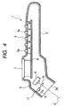
- Fig. 4 is a diagram schematically showing a mechanical arrangement of a two-dimensional code reading apparatus 1 serving as an optical information reading apparatus in accordance with this embodiment.
- the two-dimensional code reading apparatus 1 includes a reading mechanism 3 and a control unit 4 (refer to Fig. 3 ) incorporated in a casing 2.
- the reading mechanism 3 is provided for reading a two-dimensional code C, such as a QR code, recorded on a catalog, a voucher, a merchandise label or other reading objective (refer to Figs. 2A and 2B ).
- the control unit 4 is chiefly arranged by a microcomputer to perform an overall control of the system as well as function as a processing means for performing read processing (and decode processing) of a two-dimensional code C based on image data being picked up by the reading mechanism 3 (i.e. area sensor).
- the casing 2 is configured into a grip portion at its proximal end (i.e. right side in the drawing) and is slightly widened at its front end.
- the front part of the casing 2 is also bent downward slightly so as to extend forward with a declining angle.
- the front end portion of the casing 2 has a reading aperture 2a.
- the key input section 5 allows a user to select a reading program and designate a code type.
- the casing 2 has a trigger switch 6 (only shown in Fig. 3 ) used for read instruction that is provided on an outer surface (e.g., on a side surface) of the casing 2.
- the trigger switch 6 is, for example, arranged to cause a two-step motion when it is depressed by a user.
- a first stage depressing action by a user i.e. a so-called half depressed condition of the switch
- a second stage depressing action by the user causes the system to execute the reading operation.
- a display section 7 which is for example arranged by an LCD (i.e. liquid crystal display), is provided on an upper surface of the casing 2.
- LCD liquid crystal display
- These key switches 5a and the display section 7 are mounted on a printed circuit board 8 disposed in the casing 2.
- the control unit 4 is also mounted on the printed circuit board 8.
- a secondary battery serving as a power source is incorporated in the casing 2.
- the reading mechanism 3 includes an area sensor 9, an image pickup lens 10, a plurality of lighting LEDs (i.e. light-emitting diodes) 11, and a plurality of lighting lenses 12.
- the area sensor 9 is, for example, arranged by a CCD (i.e. charge coupled device) image pickup element so as to serve as an image pickup means of the present invention.
- the image pickup lens 10 is positioned in front of the area sensor 9.
- Each lighting LED 11 serves as a lighting source emitting a light during a code reading operation.
- each lighting lens 12 is positioned in front of a corresponding lighting LED 11.
- the area sensor 9 is arranged to have a two-dimensional imaging visual field F consisting of, for example, lateral 640 pixels x vertical 480 pixels (refer to Figs. 2A, 2B and 5 to 7 ).
- the image pickup lens 10 is disposed at the center of a reading aperture 2a with a plurality of lighting lenses 12 disposed around it (e.g. at an obliquely upper portion).
- a user brings the reading aperture 2a to the vicinity of a reading objective (voucher, label, catalog. etc.) on which a code C is recorded or printed and then performs a reading operation, i.e. turns on the trigger switch 6.
- the system causes the lighting LED 11 to irradiate the reading objective.
- the area sensor 9 captures an image of the reading objective (i.e. performs an image pickup operation).
- the control unit 4 performs read (decode) processing for this two-dimensional code C.
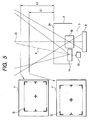
- the reading mechanism 3 includes a guide light laser diode 13 serving as a guide light irradiating means and a floodlight lens 14 as shown in Fig. 5 .
- the guide light laser diode 13 and the floodlight lens 14 are, for example, positioned on the side (e.g. left in the drawing) of the area sensor 9 (and image pickup lens 10). As shown in Figs. 2A and 2B , they irradiate a guide light G toward a reading objective to indicate a reading portion.
- the reading portion is set as a rectangular two-dimensional region that is smaller than the imaging visual field F of the area sensor 9.
- the guide light G is a line segment light indicating an outer periphery (i.e. a frame) of this two-dimensional region. More specifically, according to this embodiment, the guide light G consists of four L-shaped light portions defining four comers of a two-dimensional region, two T-shaped light portions indicating respective centers of right and left sides of this two-dimensional region, and a cross light portion indicating a center of the two-dimensional region.
- An optical axis P of the guide light irradiating means (i.e. guide light laser diode 13) does not physically agree with (i.e. inclines with respect to) an optical axis O of a light received by the area sensor 9. Therefore, as shown in Fig. 5 , the irradiated position of the guide light G shifts on the imaging visual field F of the area sensor 9 in accordance with a change of the distance between the reading aperture 2a and the reading objective. More specifically, when the distance between the reading aperture 2a and the reading objective is short (i.e. distance L1), the irradiated guide light G is offset toward a left side of the imaging visual field F. On the other hand, when the distance between the reading aperture 2a and the reading objective is long (i.e. distance L2), the irradiated guide light G is offset toward a right side of the imaging visual field F.
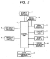
- Fig. 3 is a circuit diagram schematically showing an electric arrangement of the two-dimensional code reading apparatus 1 including the control unit 4 as a main component.
- the control unit 4 inputs operation signals of the key input section 5 and the trigger switch 6 and controls the display section 7.
- the control unit 4 controls each lighting LED 11 and the guide light laser diode 13.
- the control unit 4 inputs picked-up image data of a reading objective captured by the area sensor 9 and performs the decode processing.
- the control unit 4 further includes an amplifier for amplifying an image pickup signal of the area sensor 9 and a binary circuit for converting a sensor signal into binary-coded data.
- An image memory 15 is connected to the control unit 4 and to the area sensor 9.
- the control unit 4 is connected to a sound generating section 16 that generates a buzzer sound upon completion of a reading operation of a two-dimensional code C.
- the control unit 4 is also connected to a data communicating section 17 that performs data communication of the decoded data with an external device (e.g. managing computer) via an infrared ray.
- the two-dimensional code reading apparatus 1 executes the following operations with a software arrangement of the control unit 4 (i.e. execution of a reading program). More specifically, when a user operates the trigger switch 6 in a half depressed condition (i.e. in response to user's first stage depressing action), the control unit 4 activates the guide light laser diode 13 to irradiate a guide light G indicating a reading portion (i.e. a two-dimensional region) on a reading objective. Subsequently, in response to a complete depression of the trigger switch 6 (i.e. in response to user's second stage depressing action), the control unit 4 causes the area sensor 9 to capture an image of the reading objective. The capturing of this image is separated into two stages.
- the area sensor 9 captures a first image under the condition that the guide light G is irradiated on the reading objective (i.e. under the condition that no lighting beam is irradiated). Subsequently, in a second stage, the area sensor 9 captures a second image under the condition that the guide light G is not irradiated on the reading objective (i.e. under the condition that the lighting beam is irradiated).
- the control unit 4 obtains an irradiated position of the guide light G on the imaging visual field F based on image data of the first image and regards a same position on the second image as the irradiating position of the guide light G.
- the irradiated position of the guide light G is sufficiently bright compared with the other portion.
- the control unit 4 can function as a detecting means of the present invention.
- the control unit 4 performs the read processing (decode processing) for a two-dimensional code C based on image data of the second image.
- the control unit 4 designates a two-dimensional code C contained in the reading portion (i.e. two-dimensional region) of the guide light G as a processing objective.
- the control unit 4 primarily designates a two-dimensional code C completely contained in the two-dimensional region as a read processing objective.
- control unit 4 in performing the decode processing, first executes the processing for estimating an existing region of a two-dimensional code C in the second image and then reads a bright and dark pattern in the estimated existing region of the two-dimensional code C.
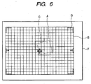
- the processing for estimating the existing region of a two-dimensional code C is performed as partly shown in Figs. 6 and 7 .
- the control unit 4 divides a captured region of a picked-up image (i.e. second image) into a plurality of image blocks B (i.e. check areas) arrayed in vertical and lateral directions. Then, the control unit 4 checks bright and dark levels of respective pixels in each image block B as well as change in the bright and dark levels. Then, based on its result (i.e. the number of bright and dark change points), the control unit 4 extracts an image block B having a higher possibility of containing at least part of a two-dimensional code C.
- each image block B has a size of 16 pixels x 16 pixels.
- this applicant has already proposed the detailed processing as disclosed in the Japanese patent application Laid-open No. 2002-304594 or in the Japanese patent application Laid-open No. 2000-353210 .
- the control unit 4 designates only an image contained in the two-dimensional region indicated by the guide light G as a processing objective image.
- the control unit 4 fails in reading (decoding) a two-dimensional code C and the cause of failure is derived from a condition that part of the two-dimensional code C exists outside the two-dimensional region indicated by the guide light G
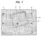
- the control unit 4 expands a processing objective region outward from the two-dimensional region and then executes the read processing again with an expanded processing objective region. Then, when it executes the read processing again, the control unit 4 expands the processing objective region so as to include a region adjacent to the two-dimensional region being estimated as containing the two-dimensional code C (refer to Fig. 7 ).
- a user shifts the reading aperture 2a of the casing 2 toward a reading objective in reading a two-dimensional code C recorded or printed on the reading objective and, under this condition, the user depresses the trigger switch 6 provided on the side surface of the casing 2 into a half depressed condition.
- This user's first stage depressing action applied on the trigger switch 6 causes the system to irradiate the guide light G onto the reading objective so as to indicate a reading portion (i.e. a two-dimensional region) as described above.
- the user can position an intended two-dimensional code C to be read within the two-dimensional region indicated by the guide light G while visually confirming the indicated reading portion on the reading objective.
- the user makes the second-stage depressing action for the trigger switch 6.
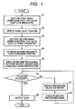
- the control unit 4 executes the read processing in accordance with the flowchart shown in Fig. 1 . More specifically, as shown in step S1, the control unit 4 causes the area sensor 9 to execute capturing of a first image under the condition that the guide light G is irradiated on the reading objective (i.e. under that condition that the lighting beam is not irradiated yet). Next, in step S2, the control unit 4 executes the processing for obtaining an irradiated position of the guide light G (i.e. a two-dimensional region defining a reading portion) on the imaging visual field F based on the captured first image data.
- an irradiated position of the guide light G i.e. a two-dimensional region defining a reading portion
- step S3 the control unit 4 deactivates the guide light laser diode 13 to stop the emission of guide light G. Instead, the control unit 4 turns on the lighting LED 11 and causes the area sensor 9 to capture the second image under the condition that a lighting beam is irradiated on the reading objective.
- step S4 the control unit 4 proceeds to the next step S4 to execute the processing for estimating the existing region of an image of a two-dimensional code C in the reading portion on the imaging visual field F (i.e. a two-dimensional region indicated by the guide light G).
- the control unit 4 divides the region of the second image into a plurality of image blocks B arrayed in vertical and lateral directions as described above (refer to Figs.
- the control unit 4 estimates the region 'A' as an existing region of the two-dimensional code C.
- step S5 the control unit 4 designates the two-dimensional code C contained in the reading portion (i.e. the two-dimensional region) as a reading objective and executes the decode processing for the designated reading objective.
- This decode processing is carried out only for the processing objective image contained in the two-dimensional region indicated by the guide light G.
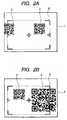
- the second image may include a plurality of (e.g. two) two-dimensional codes C that are present on the imaging visual field F as shown in Fig. 2A .
- the control unit 4 primarily designates one two-dimensional code C as a read processing objective if it is completely contained in the reading portion (i.e. in the two-dimensional region).
- control unit 4 selects a two-dimensional code C positioned on the right side of the drawing as a reading objective.
- the control unit 4 selects a two-dimensional code C having a largest area contained in the reading portion and executes the decoding processing for the selected code.
- control unit 4 selects a two-dimensional code C positioned on the left side of the drawing as a reading objective.
- an objective region for the decode processing is not equal to the entire region of the imaging visual field F and is limited to the reading portion (i.e. two-dimensional region) narrower than the imaging visual field F of the area sensor 9 and further limited to the existing region through the above-described step S4 (i.e. the region indicated by a bold line 'A' in Fig. 6 ). Hence, it becomes possible to shorten the processing time correspondingly.
- step S6 the control unit 4 makes a judgment as to whether or not the decode processing for the selected two-dimensional code C is successful.
- the control unit 4 outputs the decoded data in the next step S9.
- the control unit 4 causes the display section 7 to display the decoded data and transmits the decoded data to a managing computer.
- the control unit 4 terminates the processing routine of the flowchart shown in Fig. 1 .
- Fig. 7 there is a case that an image of the two-dimensional code C may be partly present out of the reading portion (i.e.
- the two-dimensional code C exits partly outside the processing objective image and accordingly the processing for decoding it will end unsuccessfully (i.e. NO in step S6).
- step S7 the control unit 4 proceeds to a step S7 to expand the processing objective region outward from the present reading portion (i.e. two-dimensional region). Then, in step S8, the control unit 4 executes the decode processing again and returns to the step S6.
- step S7 the control unit 4 expands the processing objective region by selectively adding a portion adjacent to a region which is estimated as containing the two-dimensional code C among the image regions (i.e. image blocks B) positioned outside (i.e. along the periphery of) the two-dimensional region. According to the example shown in Fig.
- the control unit 4 expands the processing objective region by adding a portion A' consisting of a plurality of blocks B and indicated as a hatched region existing along the upper side of the reading portion (i.e. two-dimensional region). With this adjustment, the control unit 4 can adequately perform the decode processing.
- control unit 4 will not fail in reading a two-dimensional code C unless the two-dimensional code C is completely out of the imaging visual field F. Furthermore, in executing the decode processing again, the control unit 4 needs not to widely expand the processing objective region so as to include unnecessary regions. Therefore, it becomes possible to prevent the processing time from becoming long.
- this embodiment uses a guide light G defining a two-dimensional region narrower than the imaging visual field F of the area sensor 9 and irradiates the guide light G to indicate a reading portion on a reading objective.
- This embodiment detects an irradiated position of the guide light G on the imaging visual field F and selects only a two-dimensional code C contained in the two-dimensional region indicated by the guide light G as a read processing objective. Accordingly, this embodiment enables the system to easily select an intended two-dimensional code C that a user wants to read among a plurality of two-dimensional codes C existing in a two-dimensional space. Furthermore, this embodiment enables the system to limit or reduce the region of an image serving as a processing objective. Thus, this embodiment can shorten the processing time.
- this embodiment divides the image region being picked up by the area sensor 9 into a plurality of image blocks B.
- This embodiment estimates an existing region of the two-dimensional code C based on the check result with respect to the bright and dark levels of pixels in each image block B as well as change in the bright and dark levels.
- this embodiment enables the system to substantially reduce the region serving as a read processing objective. The processing time can be further shortened.
- this embodiment selects only an image contained in the two-dimensional region indicated by the guide light G as a processing objective image.
- this embodiment expands the processing objective region outward so as to include an adjacent region and executes the decode processing again.
- this embodiment can eliminate reading errors of this two-dimensional code C.
- this embodiment can prevent the processing time required in this case from becoming long.
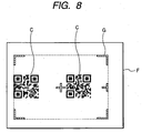
- Fig. 8 is a view showing another embodiment of the present invention.
- a plurality of two-dimensional codes C recorded or printed on a reading objective are disposed with a relatively short distance between them.
- These plural (two in this example) two-dimensional codes C are completely present in a two-dimensional region indicated by the guide light G on the imaging visual field F.
- the control unit 4 designates one two-dimensional code C closest in distance to a central position of the two-dimensional region as a read processing objective (i.e. a right one in the drawing).
- this embodiment can reduce the processing time but also this embodiment enable a user to surely accomplish the read processing for an intended two-dimensional code C only.
- the control unit 4 expands the processing objective region outward so as to include an adjacent region and executes the decode processing again.
- the detecting means can be modified so as to indirectly obtain the position of the guide light G on the imaging visual field F based on the measured reading distance.
- the present invention is not limited to the above-described embodiments.
- the irradiation pattern of the guide light it is also possible to irradiate a light having the shape of a plurality of line segments or points in projection for defining a frame along an outer periphery of a two-dimensional region. It is also possible to use a light irradiating the entire of a two-dimensional region.
- the optical information reading apparatus according to the present invention is not limited to a reading operation for a two-dimensional code and therefore can be used for reading a bar code or other one-dimensional code. In this respect, the present invention can be adequately modified and brought into practice without departing from the scope of the claims.
Landscapes
- Physics & Mathematics (AREA)
- Engineering & Computer Science (AREA)
- Electromagnetism (AREA)
- Artificial Intelligence (AREA)
- Toxicology (AREA)
- General Health & Medical Sciences (AREA)
- Health & Medical Sciences (AREA)
- Computer Vision & Pattern Recognition (AREA)
- General Physics & Mathematics (AREA)
- Theoretical Computer Science (AREA)
- Image Input (AREA)
- Image Processing (AREA)
- Length Measuring Devices By Optical Means (AREA)
- Character Input (AREA)
Claims (16)
- Lesevorrichtung für optische Informationen, mit
einer Bildaufnahmeinrichtung (9), die ein zweidimensionales Bildaufnahmefeld (F) zum Aufnehmen eines Bildes eines Leseobjekts, das einen darin enthaltenen Informationscode (C) aufweist;
einer Führungslichtausstrahlungseinrichtung (13) zum Bestrahlen des Leseobjekts mit einem Führungslicht (G), um einen Lesebereich zu markieren;
einer Verarbeitungseinrichtung (4) zur Leseverarbeitung des Informationscodes (C) auf der Basis des durch die Bildaufnahmeinrichtung (9) aufgenommenen Bildes,
wobei das von der Führungslichtausstrahlungseinrichtung (13) ausgestrahlte Führungslicht (G) eine zweidimensionale Region als einen Lesebereich markiert, der kleiner als das Bildaufnahmefeld (F) ist, und
wobei eine Erfassungseinrichtung (4) vorgesehen ist, um eine durch das Führungslicht (G) beleuchtete Position auf dem Bildaufnahmefeld (F) der Bildaufnahmeeinrichtung zu erfassen,
dadurch gekennzeichnet, dass
die Verarbeitungseinrichtung (4) aufgrund des Ergebnisses der Erfassung durch die Erfassungseinrichtung (4) die zweidimensionale Region als den Lesebereich in dem durch die Bildaufnahmeinrichtung (9) aufgenommenen Bild des Leseobjekts festlegt und einen Informationscode liest und verarbeitet, der vollständig in der zweidimensionalen Region enthalten ist, wenn mehrere Codes (C) in der zweidimensionalen Region vorhanden sind. - Lesevorrichtung für optische Informationen nach Anspruch 1, wobei die Führungslichtausstrahlungseinrichtung (13) zur Ausstrahlung von linienförmigem, linienabschnittsförmigem oder punktförmigem Licht in Projektion entlang des äußeren Randes der zweidimensionalen Region oder zur vollständigen Ausleuchtung der zweidimensionalen Region ausgelegt ist.
- Lesevorrichtung für optische Informationen nach Anspruch 1 oder 2, wobei
die Bildaufnahmeinrichtung (9) unter der Bedingung, dass das Führungslicht (G) auf das Leseobjekt strahlt, ein erstes Bild aufnimmt und danach unter der Bedingung, dass das Führungslicht (G) nicht auf das Leseobjekt strahlt, ein zweites Bild aufnimmt, und
die Erfassungseinrichtung (4) die durch das Führungslicht (G) beleuchtete Position auf dem Bildaufnahmefeld (F) auf der Basis der Daten des ersten Bildes ermittelt und die gleiche Position auf dem zweiten Bild als die durch das Führungslicht (G) beleuchtete Position bewertet. - Lesevorrichtung für optische Informationen nach einem der Ansprüche 1 bis 3, wobei die Verarbeitungseinrichtung (4) ausgelegt ist, eine Region eines aufgenommenen Bildes, aufgenommen durch die Bildaufnahmeeinrichtung (9), in eine Mehrzahl von Blöcken aufzuteilen, Hell- und Dunkelpegel der jeweiligen Pixel in jedem Bildblock und auch Änderungen der Hell- und Dunkelpegel zu prüfen, und eine existierende Region des Informationscodes (C) abzuschätzen in dem die Möglichkeit des Enthaltenseins wenigstens eines Teils des Informationscodes (C) in jedem der Bildblöcke auf der Basis des Ergebnisses des Prüfprozesses beurteilt wird.
- Lesevorrichtung für optische Informationen nach einem der Ansprüche 1 bis 4, wobei die Verarbeitungseinrichtung (4) nur das in der durch das Führungslicht (G) markierten zweidimensionalen Region enthaltene Bild als ein zu verarbeitendes Objektbild auswählt.
- Lesevorrichtung für optische Informationen nach Anspruch 5, wobei die Verarbeitungseinrichtung (4) den Informationscodes (C) auswählt, der einer Mittenposition in der zweidimensionalen Region als das zu verarbeitende Objektbild am nahesten ist, wenn eine Mehrzahl von Informationscodes (C) vollständig in der durch das Führungslicht (G) markierten zweidimensionalen Region enthalten sind.
- Lesevorrichtung für optische Informationen nach Anspruch 5, wobei die Verarbeitungseinrichtung (4) in dem Fall, dass das Lesen des Informationscodes (C) fehlschlägt und der Grund für das Fehlschlagen darin liegt, dass ein Teil des Informationscodes (C) außerhalb der durch das Führungslicht (G) markierten zweidimensionalen Region liegt, eine zu verarbeitende Objektregion über die zweidimensionale Region hinaus erweitert und dann den Leseprozess erneut mit der erweiterten zu verarbeitenden Objektregion durchführt.
- Lesevorrichtung für optische Informationen nach Anspruch 7, wobei die Verarbeitungseinrichtung (4), wenn sie die Leseprozess erneut durchführt, die zu verarbeitende Objektregion derart erweitert, dass eine zu der bestehenden Region benachbarte Region hinzugenommen wird, bei der abgeschätzt worden ist, dass sie den Informationscodes (C) enthält.
- Ein Verfahren zum optischen Lesen eines Informationscodes, mit den Schritten:Bestrahlen eines Leseobjekts mit einem Führungslicht (G), das einen zweidimensionalen Lesebereich markiert, der kleiner als ein Bildaufnahmefeld (F) einer Bildaufnahmeinrichtung (9) ist;Aufnehmen eines ersten Bildes des unter Beleuchtung mit den Führungslicht (G) stehenden Leseobjekts;Erfassen der Position des Führungslichts (G) auf der Basis der aufgenommenen ersten Bilddaten;Aufnehmen eines zweiten Bildes des Leseobjekts nach dem die Beleuchtung mit dem Führungslicht beendet wurde;Abschätzen einer existierenden Region eines Informationscodes (C) in dem zweiten Bild;Festlegen einer zweidimensionalen Region in dem zweiten Bild als ein Lesebereich;Auswählen nur eines solchen Informationscodes (C) als Bearbeitungsziel, der vollständig in dem zweiten Bild der zweidimensionalen Region als ein Lesebereich enthalten ist, wenn eine Mehrzahl von Codes (C) in dem zweiten Bild des durch das Führungslicht (G) markierten zweidimensionalen Lesebereichs enthalten sind; undAusführen des Dekodierprozesses nur für den ausgewählten Informationscode (C).
- Das Verfahren zum optischen Lesen eines Informationscodes nach Anspruch 9, wobei das Führungslicht (G) die Form einer Linie, eines Linienabschnitts oder eines Punktes in Projektion entlang des äußeren Randes des zweidimensionalen Lesebereiches besitzt oder wobei das Führungslicht (G) ein Licht ist, das die gesamte Region des zweidimensionalen Lesebereichs ausleuchtet.
- Das Verfahren zum optischen Lesen eines Informationscodes nach einem der Ansprüche 9 bis 10, mit den weiteren Schritten:Herleiten einer mit dem Führungslicht (G) beleuchteten Position auf dem Bildaufnahmefeld (F) auf der Basis der Daten des ersten Bildes, undBewerten der Position auf dem zweiten Bild, die der durch das Führungslicht (G) beleuchteten Position entspricht.
- Das Verfahren zum optischen Lesen eines Informationscodes nach einem der Ansprüche 9 bis 11, mit den weiteren Schritten:Aufteilen einer Region eines aufgenommenen Bildes, aufgenommen durch die Bildaufnahmeeinrichtung (9), in eine Mehrzahl von Blöcken,Überprüfen der Hell- und Dunkelpegel der jeweiligen Pixel in jedem Bildblock und auch der Änderungen der Hell- und Dunkelpegel, undAbschätzen einer existierenden Region des Informationscodes (C) in dem die Möglichkeit des Enthaltenseins wenigstens eines Teils des Informationscodes (C) in jedem der Bildblöcke auf der Basis des Ergebnisses des Überprüfungsschritts beurteilt wird.
- Das Verfahren zum optischen Lesen eines Informationscodes nach einem der Ansprüche 9 bis 12, mit dem Schritt des Auswählens eines in dem durch das Führungslicht (G) markierten zweidimensionalen Lesebereich enthaltenden Bildes als zu verarbeitendes Objektbild.
- Das Verfahren zum optischen Lesen eines Informationscodes nach einem der Ansprüche 9 bis 13, mit dem Schritt des Auswählens eines Informationscodes (C) als das lesend zu verarbeitende Objekt, der einer Mittenposition des zweidimensionalen Lesebereichs am nahesten ist, wenn eine Mehrzahl von Informationscodes (C) vollständig in dem durch das Führungslicht (G) markierten zweidimensionalen Lesebereich enthalten sind.
- Das Verfahren zum optischen Lesen eines Informationscodes nach einem der Ansprüche 9 bis 14, mit dem Schritt des Erweiterns einer zu verarbeitenden Objektregion über den zweidimensionalen Lesebereich hinaus und anschließender Leseverarbeitung der erweiterten zu verarbeitenden Objektregion, falls der Informationscode (C) nicht gelesen werden kann und der Fehlschlag darauf zurückzuführen ist, dass ein Teil des Informationscodes (C) außerhalb des durch das Führungslicht (G) markierten zweidimensionalen Lesebereichs liegt.
- Das Verfahren zum optischen Lesen eines Informationscodes nach Anspruch 15, wobei bei der Leseverarbeitung die zu verarbeitende Objektregion derart erweitert ist, dass eine zu der bestehenden Region benachbarte Region hinzugenommen wird, bei der abgeschätzt worden ist, dass sie den Informationscodes (C) enthält.
Applications Claiming Priority (2)
| Application Number | Priority Date | Filing Date | Title |
|---|---|---|---|
| JP2003315537 | 2003-09-08 | ||
| JP2003315537A JP4058529B2 (ja) | 2003-09-08 | 2003-09-08 | 光学情報読取装置 |
Publications (3)
| Publication Number | Publication Date |
|---|---|
| EP1513095A2 EP1513095A2 (de) | 2005-03-09 |
| EP1513095A3 EP1513095A3 (de) | 2008-09-24 |
| EP1513095B1 true EP1513095B1 (de) | 2011-11-09 |
Family
ID=34131933
Family Applications (1)
| Application Number | Title | Priority Date | Filing Date |
|---|---|---|---|
| EP04016984A Expired - Lifetime EP1513095B1 (de) | 2003-09-08 | 2004-07-19 | Optische Informationslesevorrichtung und Leseverfahren |
Country Status (5)
| Country | Link |
|---|---|
| US (1) | US7503492B2 (de) |
| EP (1) | EP1513095B1 (de) |
| JP (1) | JP4058529B2 (de) |
| KR (1) | KR100626329B1 (de) |
| CN (1) | CN1299229C (de) |
Families Citing this family (31)
| Publication number | Priority date | Publication date | Assignee | Title |
|---|---|---|---|---|
| US7721966B2 (en) * | 2004-10-18 | 2010-05-25 | Datalogic Scanning, Inc. | System and method of optical reading employing virtual scan lines |
| JP4254724B2 (ja) | 2005-02-16 | 2009-04-15 | 株式会社デンソーウェーブ | バーコード読取り方法及びコンピュータプログラム |
| KR100784200B1 (ko) * | 2005-10-24 | 2007-12-11 | 주식회사 케이티프리텔 | 이미지에 따른 코드 정보를 내장한 코드의 판독 방법 및장치 |
| CN101237638B (zh) * | 2007-02-02 | 2013-01-30 | 银河联动信息技术(北京)有限公司 | 动态信息发布的系统和方法 |
| JP2009129227A (ja) * | 2007-11-26 | 2009-06-11 | Toshiba Mach Co Ltd | 制御装置、工作機械、及び表示方法 |
| JP4968043B2 (ja) * | 2007-12-19 | 2012-07-04 | 株式会社デンソーウェーブ | 光学的情報読取装置 |
| US8074173B2 (en) | 2008-05-08 | 2011-12-06 | Microsoft Corporation | Associating input with computer based content |
| JP5104713B2 (ja) * | 2008-10-17 | 2012-12-19 | 株式会社デンソーウェーブ | 光学的情報読取装置 |
| JP5083676B2 (ja) * | 2010-02-16 | 2012-11-28 | 株式会社デンソーウェーブ | 読取システム、及び光学的情報読取装置 |
| CN101885391B (zh) * | 2010-06-04 | 2012-05-30 | 北京赛腾工业标识系统有限公司 | 一种产品赋码标识信息采集装置及方法 |
| JP5130387B2 (ja) * | 2010-08-26 | 2013-01-30 | 東芝テック株式会社 | コード読取装置および商品情報処理システム |
| JP2012073822A (ja) * | 2010-09-29 | 2012-04-12 | Panasonic Corp | 帳票読取装置 |
| CN102646186A (zh) * | 2012-02-27 | 2012-08-22 | 北京恒信彩虹科技有限公司 | 二维码读取方法、设备、装置,计算机及二维码读取系统 |
| CN102930192B (zh) * | 2012-09-19 | 2016-02-03 | 腾讯科技(深圳)有限公司 | 安全信息生成和获取方法、及相关装置 |
| CN105590077A (zh) * | 2014-10-24 | 2016-05-18 | 秀传医疗财团法人彰滨秀传纪念医院 | 红外线辨认定位系统及其读取方法 |
| CN104504553A (zh) * | 2014-12-31 | 2015-04-08 | 刘训志 | 一种物流收发件信息录入和处理方法 |
| CN104678953B (zh) * | 2015-01-23 | 2017-08-18 | 深圳市捷佳伟创新能源装备股份有限公司 | 一种用于硅片生产的石墨舟识别系统及方法 |
| CN104615786A (zh) * | 2015-03-04 | 2015-05-13 | 庞迪 | 一种基于二维码图形的公交车信息查询方法及系统 |
| CN105005754B (zh) * | 2015-08-14 | 2018-05-29 | 福建联迪商用设备有限公司 | 一种共用补光灯和对准灯的二维码扫描器 |
| CN105404837A (zh) * | 2015-11-17 | 2016-03-16 | 上海斐讯数据通信技术有限公司 | 一种物品定位方法及系统 |
| JP2017187988A (ja) * | 2016-04-07 | 2017-10-12 | 東芝テック株式会社 | コード認識装置 |
| CN109478225A (zh) * | 2016-08-09 | 2019-03-15 | 株式会社明日星 | 读取装置、程序以及单元 |
| US9798912B1 (en) * | 2016-09-26 | 2017-10-24 | Symbol Technologies, Llc | Imaging module and reader for, and method of, reading targets by image capture with a substantially constant resolution over an extended range of working distances |
| KR102169308B1 (ko) * | 2016-12-16 | 2020-10-23 | 주식회사 디비하이텍 | 이미지 센서 및 이미지 센서의 센싱 방법 |
| US10169631B2 (en) * | 2017-03-06 | 2019-01-01 | International Business Machines Corporation | Recognizing fingerprints and fingerprint combinations as inputs |
| US11049279B2 (en) * | 2018-03-27 | 2021-06-29 | Denso Wave Incorporated | Device for detecting positional relationship among objects |
| US10671824B2 (en) * | 2018-04-17 | 2020-06-02 | Zebra Technologies Corporation | Decoding designated barcode in field of view of barcode reader |
| JP7366577B2 (ja) * | 2019-04-15 | 2023-10-23 | 株式会社キーエンス | 光学式情報読取装置及び光学式情報読取方法 |
| JP7795320B2 (ja) * | 2021-01-18 | 2026-01-07 | 株式会社キーエンス | 光学的情報読取装置 |
| JP2022134482A (ja) * | 2021-03-03 | 2022-09-15 | 株式会社キーエンス | 光学的情報読取装置 |
| CN115140471B (zh) * | 2022-06-29 | 2024-01-02 | 山东西部智能科技有限公司 | 一种物品管理方法、系统、设备及计算机可读存储介质 |
Family Cites Families (20)
| Publication number | Priority date | Publication date | Assignee | Title |
|---|---|---|---|---|
| ATE185635T1 (de) * | 1992-03-12 | 1999-10-15 | Norand Corp | Leser zum dekodieren zwei-dimensionaler optischer information |
| AU668987B2 (en) * | 1992-09-28 | 1996-05-23 | Olympus Optical Co., Ltd. | Dot code and information recording/reproducing system for recording/reproducing dot code |
| JPH06266876A (ja) * | 1993-03-15 | 1994-09-22 | Tokyo Electric Co Ltd | 2次元コードスキャナ |
| JPH0793459A (ja) * | 1993-09-28 | 1995-04-07 | Tec Corp | 2次元コードスキャナ |
| KR950020294A (ko) * | 1993-12-15 | 1995-07-24 | 키시나 요 | 2-차원 코드데이터의 판독장치 및 판독방법 |
| US5500516A (en) * | 1994-08-30 | 1996-03-19 | Norand Corporation | Portable oblique optical reader system and method |
| US5550516A (en) | 1994-12-16 | 1996-08-27 | Honeywell Inc. | Integrated resonant microbeam sensor and transistor oscillator |
| JP3118500B2 (ja) * | 1995-02-23 | 2000-12-18 | 東芝テック株式会社 | コードリーダ |
| JPH0997304A (ja) * | 1995-10-02 | 1997-04-08 | Sumitomo Electric Ind Ltd | 光学式情報読取装置 |
| US6034379A (en) | 1996-03-01 | 2000-03-07 | Intermec Ip Corp. | Code reader having replaceable optics assemblies supporting multiple illuminators |
| JP3331300B2 (ja) | 1997-02-06 | 2002-10-07 | シャープ株式会社 | 光学読取り装置 |
| US6340114B1 (en) * | 1998-06-12 | 2002-01-22 | Symbol Technologies, Inc. | Imaging engine and method for code readers |
| JP3952613B2 (ja) | 1998-10-23 | 2007-08-01 | 株式会社デンソー | 光学式情報読取装置 |
| JP4288756B2 (ja) | 1999-04-08 | 2009-07-01 | 株式会社デンソー | 情報コード概略存在領域推定方法、情報コード読取方法及び装置、記録媒体 |
| JP2001147987A (ja) | 1999-11-24 | 2001-05-29 | Denso Corp | 光学情報読取装置 |
| JP3632578B2 (ja) | 2000-09-14 | 2005-03-23 | 株式会社デンソー | 光学式情報読取装置 |
| JP2002140662A (ja) | 2000-11-06 | 2002-05-17 | Matsushita Electric Ind Co Ltd | 光学的情報読取装置 |
| EP1717728B1 (de) * | 2001-01-22 | 2010-09-01 | Hand Held Products, Inc. | Optisches Lesegerät mit Partial-Frame-Betriebsmodus |
| JP3890991B2 (ja) | 2001-01-31 | 2007-03-07 | 株式会社デンソー | 情報コード存在推定方法,情報コード読取装置及び情報コード存在推定プログラム |
| JP4059173B2 (ja) * | 2003-06-27 | 2008-03-12 | 株式会社デンソーウェーブ | 光学的情報読取装置および光学的情報の読取方法 |
-
2003
- 2003-09-08 JP JP2003315537A patent/JP4058529B2/ja not_active Expired - Fee Related
-
2004
- 2004-07-19 EP EP04016984A patent/EP1513095B1/de not_active Expired - Lifetime
- 2004-07-20 US US10/893,879 patent/US7503492B2/en active Active
- 2004-08-04 KR KR1020040061416A patent/KR100626329B1/ko not_active Expired - Fee Related
- 2004-09-08 CN CNB2004100768563A patent/CN1299229C/zh not_active Expired - Fee Related
Also Published As
| Publication number | Publication date |
|---|---|
| JP4058529B2 (ja) | 2008-03-12 |
| US7503492B2 (en) | 2009-03-17 |
| CN1299229C (zh) | 2007-02-07 |
| EP1513095A3 (de) | 2008-09-24 |
| KR20050025894A (ko) | 2005-03-14 |
| EP1513095A2 (de) | 2005-03-09 |
| KR100626329B1 (ko) | 2006-09-20 |
| US20050051627A1 (en) | 2005-03-10 |
| CN1595421A (zh) | 2005-03-16 |
| JP2005084890A (ja) | 2005-03-31 |
Similar Documents
| Publication | Publication Date | Title |
|---|---|---|
| EP1513095B1 (de) | Optische Informationslesevorrichtung und Leseverfahren | |
| JP4186915B2 (ja) | 光学情報読取装置 | |
| EP1492044B1 (de) | Vorrichtung und Verfahren zum Lesen von optischen Informationen | |
| US20120097744A1 (en) | Arrangement For And Method Of Reducing Vertical Parallax Between An Aiming Pattern And An Imaging Field Of View In A Linear Imaging Reader | |
| CN112055858A (zh) | 解码条形码读取器的视场中指定的条形码 | |
| JP4403975B2 (ja) | 光学情報読取装置 | |
| JP4389812B2 (ja) | 光学情報読取装置 | |
| KR102079697B1 (ko) | 판독장치, 프로그램 및 유닛 | |
| US20060138234A1 (en) | Methods and apparatus for improving direct part mark scanner performance | |
| JP2010086182A (ja) | 光学的情報読取装置 | |
| JP2011008574A (ja) | 光学的情報読取装置 | |
| JP4058478B2 (ja) | 光学的情報の読取方法 | |
| JP7167553B2 (ja) | 二次元コード | |
| JP2018045347A (ja) | 光学的情報読取装置 | |
| JP4111216B2 (ja) | 光学情報読取装置 | |
| JP4650138B2 (ja) | 光学的情報読取装置 | |
| JP5104713B2 (ja) | 光学的情報読取装置 | |
| EP2370930B1 (de) | Minimieren von fehldecodierungen in elektrooptischen lesern | |
| CN110119645A (zh) | 条形码读取装置、条形码读取方法、计算机可读记录介质 | |
| CN113343723B (zh) | 发光装置、发光方法及计算机可读介质 | |
| JP4175223B2 (ja) | 光学式情報読取装置 | |
| JP5888199B2 (ja) | バーコード読取装置 | |
| JP2011048561A (ja) | 光学的情報読取装置 | |
| JP2006134160A (ja) | 光学式情報読取装置 | |
| JP6065719B2 (ja) | 光学的情報読取装置 |
Legal Events
| Date | Code | Title | Description |
|---|---|---|---|
| PUAI | Public reference made under article 153(3) epc to a published international application that has entered the european phase |
Free format text: ORIGINAL CODE: 0009012 |
|
| AK | Designated contracting states |
Kind code of ref document: A2 Designated state(s): AT BE BG CH CY CZ DE DK EE ES FI FR GB GR HU IE IT LI LU MC NL PL PT RO SE SI SK TR |
|
| AX | Request for extension of the european patent |
Extension state: AL HR LT LV MK |
|
| PUAL | Search report despatched |
Free format text: ORIGINAL CODE: 0009013 |
|
| AK | Designated contracting states |
Kind code of ref document: A3 Designated state(s): AT BE BG CH CY CZ DE DK EE ES FI FR GB GR HU IE IT LI LU MC NL PL PT RO SE SI SK TR |
|
| AX | Request for extension of the european patent |
Extension state: AL HR LT LV MK |
|
| 17P | Request for examination filed |
Effective date: 20081002 |
|
| 17Q | First examination report despatched |
Effective date: 20081117 |
|
| AKX | Designation fees paid |
Designated state(s): DE GB IT |
|
| GRAP | Despatch of communication of intention to grant a patent |
Free format text: ORIGINAL CODE: EPIDOSNIGR1 |
|
| GRAS | Grant fee paid |
Free format text: ORIGINAL CODE: EPIDOSNIGR3 |
|
| GRAA | (expected) grant |
Free format text: ORIGINAL CODE: 0009210 |
|
| RAP1 | Party data changed (applicant data changed or rights of an application transferred) |
Owner name: DENSO WAVE INCORPORATED |
|
| AK | Designated contracting states |
Kind code of ref document: B1 Designated state(s): DE GB IT |
|
| REG | Reference to a national code |
Ref country code: GB Ref legal event code: FG4D |
|
| REG | Reference to a national code |
Ref country code: DE Ref legal event code: R096 Ref document number: 602004035195 Country of ref document: DE Effective date: 20120119 |
|
| PLBE | No opposition filed within time limit |
Free format text: ORIGINAL CODE: 0009261 |
|
| STAA | Information on the status of an ep patent application or granted ep patent |
Free format text: STATUS: NO OPPOSITION FILED WITHIN TIME LIMIT |
|
| 26N | No opposition filed |
Effective date: 20120810 |
|
| REG | Reference to a national code |
Ref country code: DE Ref legal event code: R097 Ref document number: 602004035195 Country of ref document: DE Effective date: 20120810 |
|
| PGFP | Annual fee paid to national office [announced via postgrant information from national office to epo] |
Ref country code: IT Payment date: 20210727 Year of fee payment: 18 |
|
| PGFP | Annual fee paid to national office [announced via postgrant information from national office to epo] |
Ref country code: GB Payment date: 20210721 Year of fee payment: 18 Ref country code: DE Payment date: 20210721 Year of fee payment: 18 |
|
| REG | Reference to a national code |
Ref country code: DE Ref legal event code: R119 Ref document number: 602004035195 Country of ref document: DE |
|
| GBPC | Gb: european patent ceased through non-payment of renewal fee |
Effective date: 20220719 |
|
| PG25 | Lapsed in a contracting state [announced via postgrant information from national office to epo] |
Ref country code: GB Free format text: LAPSE BECAUSE OF NON-PAYMENT OF DUE FEES Effective date: 20220719 Ref country code: DE Free format text: LAPSE BECAUSE OF NON-PAYMENT OF DUE FEES Effective date: 20230201 |
|
| PG25 | Lapsed in a contracting state [announced via postgrant information from national office to epo] |
Ref country code: IT Free format text: LAPSE BECAUSE OF NON-PAYMENT OF DUE FEES Effective date: 20220719 |