EP1512817B1 - Fitting for doors, windows or the like - Google Patents
Fitting for doors, windows or the like Download PDFInfo
- Publication number
- EP1512817B1 EP1512817B1 EP04015108A EP04015108A EP1512817B1 EP 1512817 B1 EP1512817 B1 EP 1512817B1 EP 04015108 A EP04015108 A EP 04015108A EP 04015108 A EP04015108 A EP 04015108A EP 1512817 B1 EP1512817 B1 EP 1512817B1
- Authority
- EP
- European Patent Office
- Prior art keywords
- hinge
- hinge pin
- adjusting element
- adjustment
- wing
- Prior art date
- Legal status (The legal status is an assumption and is not a legal conclusion. Google has not performed a legal analysis and makes no representation as to the accuracy of the status listed.)
- Expired - Lifetime
Links
- 238000005553 drilling Methods 0.000 abstract 2
- 238000006073 displacement reaction Methods 0.000 description 4
- 230000014759 maintenance of location Effects 0.000 description 2
- 238000004519 manufacturing process Methods 0.000 description 1
Images


Classifications
-
- E—FIXED CONSTRUCTIONS
- E05—LOCKS; KEYS; WINDOW OR DOOR FITTINGS; SAFES
- E05D—HINGES OR SUSPENSION DEVICES FOR DOORS, WINDOWS OR WINGS
- E05D7/00—Hinges or pivots of special construction
- E05D7/0009—Adjustable hinges
- E05D7/0018—Adjustable hinges at the hinge axis
- E05D7/0045—Adjustable hinges at the hinge axis in a radial direction
- E05D2007/0072—Adjustable hinges at the hinge axis in a radial direction with sliding sleeves
-
- E—FIXED CONSTRUCTIONS
- E05—LOCKS; KEYS; WINDOW OR DOOR FITTINGS; SAFES
- E05D—HINGES OR SUSPENSION DEVICES FOR DOORS, WINDOWS OR WINGS
- E05D7/00—Hinges or pivots of special construction
- E05D7/0009—Adjustable hinges
- E05D7/0018—Adjustable hinges at the hinge axis
- E05D7/0045—Adjustable hinges at the hinge axis in a radial direction
- E05D2007/0081—Adjustable hinges at the hinge axis in a radial direction with swinging or rolling sleeves
-
- E—FIXED CONSTRUCTIONS
- E05—LOCKS; KEYS; WINDOW OR DOOR FITTINGS; SAFES
- E05D—HINGES OR SUSPENSION DEVICES FOR DOORS, WINDOWS OR WINGS
- E05D7/00—Hinges or pivots of special construction
- E05D7/0009—Adjustable hinges
- E05D7/0018—Adjustable hinges at the hinge axis
- E05D7/0045—Adjustable hinges at the hinge axis in a radial direction
- E05D7/0054—Adjustable hinges at the hinge axis in a radial direction by means of eccentric parts
-
- E—FIXED CONSTRUCTIONS
- E05—LOCKS; KEYS; WINDOW OR DOOR FITTINGS; SAFES
- E05D—HINGES OR SUSPENSION DEVICES FOR DOORS, WINDOWS OR WINGS
- E05D7/00—Hinges or pivots of special construction
- E05D7/04—Hinges adjustable relative to the wing or the frame
- E05D7/0415—Hinges adjustable relative to the wing or the frame with adjusting drive means
-
- E—FIXED CONSTRUCTIONS
- E05—LOCKS; KEYS; WINDOW OR DOOR FITTINGS; SAFES
- E05Y—INDEXING SCHEME ASSOCIATED WITH SUBCLASSES E05D AND E05F, RELATING TO CONSTRUCTION ELEMENTS, ELECTRIC CONTROL, POWER SUPPLY, POWER SIGNAL OR TRANSMISSION, USER INTERFACES, MOUNTING OR COUPLING, DETAILS, ACCESSORIES, AUXILIARY OPERATIONS NOT OTHERWISE PROVIDED FOR, APPLICATION THEREOF
- E05Y2900/00—Application of doors, windows, wings or fittings thereof
- E05Y2900/10—Application of doors, windows, wings or fittings thereof for buildings or parts thereof
- E05Y2900/13—Type of wing
- E05Y2900/132—Doors
-
- E—FIXED CONSTRUCTIONS
- E05—LOCKS; KEYS; WINDOW OR DOOR FITTINGS; SAFES
- E05Y—INDEXING SCHEME ASSOCIATED WITH SUBCLASSES E05D AND E05F, RELATING TO CONSTRUCTION ELEMENTS, ELECTRIC CONTROL, POWER SUPPLY, POWER SIGNAL OR TRANSMISSION, USER INTERFACES, MOUNTING OR COUPLING, DETAILS, ACCESSORIES, AUXILIARY OPERATIONS NOT OTHERWISE PROVIDED FOR, APPLICATION THEREOF
- E05Y2900/00—Application of doors, windows, wings or fittings thereof
- E05Y2900/10—Application of doors, windows, wings or fittings thereof for buildings or parts thereof
- E05Y2900/13—Type of wing
- E05Y2900/148—Windows
Definitions
- the invention relates to a tape for doors, windows or the like corresponding to the preamble of claim 1 Art.
- Such bands are used for the pivotable attachment of an opening optionally closing wing to the opening-limiting components - usually a frame. They comprise at least one connectable to the fixed component frame hinge part, connectable to the wing leaf hinge part and the two band parts at least partially passing through the hinge pin whose longitudinal axis defines the pivot axis of the band.
- the one band part is usually attached to the frame and therefore called “frame band part” below. Accordingly, the other hinge part is called “wing hinge part”. It is understood that these terms are not to be interpreted as limiting.
- Modern hinges for doors, windows and the like have not only their hinge function but also the ability to adjust the wing in the frame opening, d. H. compensate for unavoidable tolerances that may arise after hanging the wing in the frame opening.
- the wing can sit too low: this requires a height adjustment.
- the wing can not sit or "hang” in the horizontal position: this requires a horizontal adjustment.
- this is done by the attachment of the band parts to a fixed component or a wing in a manner that allows a relative displacement after loosening the mounting screws. If the mounting screws are accessible with the sash closed, the adjustment can be made in a simple manner by tightening the mounting screws only when the sash is closed.
- the disadvantage of this is that in this type of arrangement of the mounting screws no protection against the dismantling of the closed wing by unauthorized persons and the wing must be kept in the setting before final tightening the mounting screws.
- band parts which have an adjusting device, which allow a horizontal adjustment of the position of a fastening part relative to a holding part of the band by means of an adjusting spindle.
- These bands usually have an adjusting spindle extending over the extension, for example, of the wing hinge part, which are braced at the ends of the fastening part, ie on the hinge part of the wing band on the one hand, and on the other side at a bend projecting at the other end of the fastening part.
- the threaded spindle passes through a seated on the retaining plate threaded piece and thus moves in the adjustment with the Mounting part with.
- the threaded hole for the spindle is difficult to manufacture.
- the invention is therefore an object of the invention to provide a band with the required adjustment, which is the adjustment of the position of the hinge pin without loosening the mounting screws or enables unhooking. Furthermore, the adjustment should be feasible without tilting the hinge pin.
- the displaceable in horizontal adjustment adjustment which acts on the hinge pin within the hinge pin bore for adjustment, slidably disposed in the adjustment in a recess which is located on the back of the fastening part, it is possible the hinge pin within the hinge part perpendicular to Swivel axis to relocate with hinged wing.
- the fixing part does not have to be solved because it is stationary.
- the adjusting element can also act on several, preferably two points on the hinge pin and thus prevent tilting.
- the adjustment can be configured in two ways: it can act directly or indirectly on the hinge pin.
- the band bolt at least partially surrounding and this leading guide is provided, which additionally prevents tilting during the adjustment and allows accurate compliance with the adjustment.
- the guide may preferably be designed as at least one engaging in the hinge pin bore bush having a slot whose longitudinal extent extends in the adjustment direction.
- the guide can also be designed as a sleeve surrounding the hinge pin, which is acted upon by the adjusting element.
- the sleeve advantageously on its outer side at least one projection which engages in at least one groove on the inside of the hinge pin bore such that during an adjustment of the adjustment, the sleeve within the elongated in the adjustment hinge pin bore completes a rotational movement.
- an eccentric arrangement or an adjusting spindle are particularly preferred.
- FIGS. 1 . 2 and 3 show a designated as a whole with 100 leaf hinge part for the horizontal adjustment of a wing.
- the band further comprises a fixed to the frame to be fixed, not shown frame hinge part.
- the band parts are pivotable relative to each other about a vertical hinge axis S, which is formed by a hinge pin B.
- the wing hinge part 100 comprises a horizontally projecting, bead-like hinge part 20 with an in the adjustment direction V oval hinge pin bore 30, which integrally discharges laterally to a plate-shaped fastening part 10 which is intended to abut with its flat back on the flat front of the wing, not shown.
- the fastening part 10 has two holes 11 passing through it in the direction of the wing, by means of which it is fastened by screws, not shown, on the wing.
- the hinge part 20 has on the inner side 31 of the hinge pin bore 30 two longitudinally extending in the direction of the hinge axis S grooves 32, which forms for the corresponding recording of the projections 41 on the outside of the hinge pin B surrounding sleeve 40.
- the sleeve 40 has on the opposite outer side in each case in the upper and lower region a bore or recess 42.
- the hinge part 20 also has on its directed in the direction of the front of the wing, not shown, wall in the upper and lower region of a slot 33 whose longitudinal extent extends in the adjustment direction and corresponds to the respective recess 42 of the sleeve 40.
- a base-like projection 14 in the region of which the fastening bores 11 are located.
- an adjusting element 50 is arranged in a recess 16.
- the adjusting element 50 has approximately the shape of a "C" open in the direction of the hinge part 20 and is horizontally displaceable via an eccentric arrangement 51 in the adjustment direction within the recess 16 parallel to the front side of the wing.
- the eccentric 51 engages on the one hand in an aligned perpendicular to the adjustment slot 54 in the adjusting element 51 and on the other hand in a through hole 13 in the fastening part 10, so that the eccentric 51 can be operated in the installed state from the outside to the adjusting element 50 within the recess 16th to shift in the adjustment direction V.
- the adjusting element 50 engages with each a provided on the "arms" 55 of the "C" mandrel 52 through the respective slot 33 in the wall of the hinge member 30 into the holes 42 of the sleeve 40, which surrounds the hinge pin B.
- a movement of the adjusting element 50 is passed through the "arms" or mandrels 52 to the sleeve 40 and thus to the hinge pin B.
- the sleeve with the hinge pin within the oval hinge pin bore 30 performs a rotational movement. Since the sleeve or the hinge pin is articulated in two places (mandrels 52), tilting is prevented and allows movement with exact retention of the orientation of the hinge pin.
- the mandrels 52 are connected via bores 53 with the arms 55 of the adjusting element 50.
- the adjusting element 50 is fastened by screws, not shown, which engage in the adjustment direction V elongated holes 12 in the fastening part 10 and engage in corresponding bores 56 in the adjusting element 50.
- the hinge pin B has in its longitudinal extent approximately centrally positioned on a circumferential groove 60, into which a grub screw 61 (see. Fig. 3 ) engages to fix the hinge pin B in its longitudinal direction.
- a grub screw 61 see. Fig. 3
- the hinge part 20 on its directed in the direction of the front of the wing, not shown wall as well as the sleeve 40 each have a corresponding bore for receiving the grub screw 61.
- the front of the fastening part 10 is usually with a in the Figures 1 - 3 not shown cap concealed, which also protects the tape part against unauthorized access from a only accessible from the rear screw.
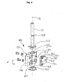
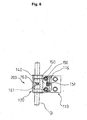
- FIGS. 4 to 6 illustrated band 200 includes as well as that of the Figures 1 - 3 an on the fixed frame to be fixed, not shown frame hinge part and the horizontally adjustable wing hinge part, which are pivotable about a vertical hinge axis S, which is formed by a hinge pin B against each other.
- the hinge part 120 has a hinge pin bore 130 which, in contrast to the hinge part 100, is not oval in the adjustment direction V and has no straight guide extending longitudinally in the direction of the hinge axis S, but an approximately semicircular cross section, so that from above and below into the hinge pin bore 130 inserted guide bushes 140 are set against rotation.
- the bushes 140 have a bore 143, which is formed elongated in the adjustment direction V and is penetrated by the hinge pin B. The bushes 140 serve to guide the hinge pin during its adjustment.
- an adjusting element 150 On the back of the plate-shaped fastening part 110, that is on the side facing the front of the wing is located in a recess 116, an adjusting element 150.
- the adjusting element 150 has approximately the shape of an "L" and extends with a leg 155 in the hinge pin bore 130 of the hinge part 120.
- the recess 116 thus opens from behind the hinge pin bore 130, so that the adjusting element 150 can protrude into this through an opening 133.
- the adjusting element 150 has no mandrels for transmitting the adjusting movement to the hinge pin B, but extending along the hinge axis S bores 153 in the legs 155 which are penetrated by the hinge pin B in the installed state.
- the hinge pin B is guided by the holes 153, so that in turn a shift is ensured under exact retention of its orientation.
- the adjusting element is also displaceable horizontally via an eccentric 151 in the adjustment direction within the recess 116 parallel to the front of the wing.
- the eccentric 151 engages on the one hand in an aligned perpendicular to the adjustment slot 154 in the adjusting element 150 and on the other hand in a through hole 113 in the fixing part 110, so that the eccentric 151 can be actuated in the installed state from the outside to the adjustment member 150 within the recess 116th to shift in the adjustment direction V.
- the adjusting element 150 protrudes with its legs 155 through the opening 133 in the wall of the hinge part 130 into the hinge pin bore and engages with one of the provided in the legs 155 of the "L" bore 153 the hinge pin B and moves it in the adjustment direction V, being guided through the holes 143 of the bushings 140.
- the hinge pin B has as in the first embodiment ( Fig. 1 ) in its longitudinal extent approximately centrally positioned on a circumferential groove 160 into which a grub screw 161 (see. Fig. 6 ) engages in order to prevent slipping or slipping out of the hinge pin.
- the adjusting element 150 has a bore 163 extending from its wall directed in the direction of the front side of the wing, not shown, in the direction of the hinge pin bore 130 for receiving the grub screw 161.
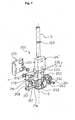
- a in the adjustment direction V-breaking, semi-circular in cross-section groove 257 is provided.
- the groove 257 has a widened location 258 for receiving and fixing the head of the spindle 251.
- the spindle 251 can not "fall out", the groove 257 is covered by a removable part 214 'of the projection 214 in the installed state.
- the spindle 251 extends into the region of the recess 216, where it engages in a corresponding threaded bore 253 in the adjusting element 250.
- the front of the fastening part 210 is covered by means of a cap 270, which can also be protected from unauthorized access by a only accessible from the rear, engaging in a bore 271 screw (not visible).
Landscapes
- Engineering & Computer Science (AREA)
- Mechanical Engineering (AREA)
- Hinges (AREA)
Abstract
Description
Die Erfindung bezieht sich auf ein Band für Türen, Fenster oder dergleichen der dem Oberbegriff des Anspruchs 1 entsprechenden Art.The invention relates to a tape for doors, windows or the like corresponding to the preamble of claim 1 Art.
Derartige Bänder dienen der schwenkbaren Befestigung eines eine Öffnung wahlweise verschließenden Flügels an den die Öffnung begrenzenden Bauteilen - üblicherweise ein Rahmen. Sie umfassen mindestens ein mit dem feststehenden Bauteil verbindbaren Rahmenbandteil, einen mit dem Flügel verbindbaren Flügelbandteil und einen die beiden Bandteile zumindest teilweise durchsetzenden Bandbolzen, dessen Längsachse die Schwenkachse des Bandes festlegt.Such bands are used for the pivotable attachment of an opening optionally closing wing to the opening-limiting components - usually a frame. They comprise at least one connectable to the fixed component frame hinge part, connectable to the wing leaf hinge part and the two band parts at least partially passing through the hinge pin whose longitudinal axis defines the pivot axis of the band.
Das eine Bandteil wird meist an dem Rahmen befestigt und daher im Folgenden "Rahmenbandteil" genannt. Dementsprechend wird das andere Bandteil "Flügelbandteil" genannt. Es versteht sich, dass diese Bezeichnungen nicht limitierend auszulegen sind.The one band part is usually attached to the frame and therefore called "frame band part" below. Accordingly, the other hinge part is called "wing hinge part". It is understood that these terms are not to be interpreted as limiting.
Moderne Bänder für Türen, Fenster und dergleichen haben außer ihrer Scharnierfunktion auch noch die Fähigkeit, den Flügel in der Rahmenöffnung zu justieren, d. h. unvermeidliche Toleranzen auszugleichen, die sich nach dem Einhängen des Flügels in die Rahmenöffnung ergeben können.Modern hinges for doors, windows and the like have not only their hinge function but also the ability to adjust the wing in the frame opening, d. H. compensate for unavoidable tolerances that may arise after hanging the wing in the frame opening.
Der Flügel kann zu tief sitzen: Dies erfordert eine Höhenverstellung. Der Flügel kann in der Horizontalen nicht an der richtigen Stelle sitzen oder "hängen": Dies erfordert eine horizontale Verstellung.The wing can sit too low: this requires a height adjustment. The wing can not sit or "hang" in the horizontal position: this requires a horizontal adjustment.
Zur Justierung des Flügels in der Öffnung ist es erforderlich, die Lage des Bandes gegenüber der Schwenkachse zu verlagern und festlegen zu können.To adjust the wing in the opening, it is necessary to shift the position of the belt relative to the pivot axis and set.
Dazu ist es einerseits möglich die Befestigungsstellen auf den Flächen des feststehenden Bauteils bzw. dessen Flügels in Längsrichtung sowie senkrecht zur Längsrichtung des Bandbolzens zu verlagern und festzulegen.For this purpose, it is on the one hand possible to shift and fix the attachment points on the surfaces of the fixed component or its wing in the longitudinal direction and perpendicular to the longitudinal direction of the hinge pin.
Im einfachsten Fall geschieht dies dadurch, dass die Befestigung der Bandteile an einem feststehenden Bauteil bzw. einem Flügel in einer Weise erfolgt, die eine Relativverschiebung nach lösen der Befestigungsschrauben erlaubt. Sind die Befestigungsschrauben bei geschlossenem Flügel zugänglich, so kann die Justierung auf einfache Weise erfolgen, indem ein Festziehen der Befestigungsschrauben erst bei geschlossenem Flügel erfolgt. Nachteilig ist hieran jedoch, dass bei dieser Art der Anordnung der Befestigungsschrauben kein Schutz gegen die Demontage des geschlossenen Flügels durch nicht autorisierte Personen besteht und der Flügel vor dem endgültigen Festziehen der Befestigungsschrauben beim Einstellen gehalten werden muss.In the simplest case, this is done by the attachment of the band parts to a fixed component or a wing in a manner that allows a relative displacement after loosening the mounting screws. If the mounting screws are accessible with the sash closed, the adjustment can be made in a simple manner by tightening the mounting screws only when the sash is closed. The disadvantage of this, however, is that in this type of arrangement of the mounting screws no protection against the dismantling of the closed wing by unauthorized persons and the wing must be kept in the setting before final tightening the mounting screws.
Ebenfalls bekannt ist z. B. aus der
Aus der
Mit diesen Bändern ist zwar eine Einstellung der "Lage" des Flügels ohne dessen Aushängen möglich, doch ändern sie nicht die Lage der Schwenkachse an sich, sondern nur die Position des Bandes am Flügel. Zudem müssen die Verstellvorrichtungen relativ "stabil" ausgeführt werden, um die Last der Flügel bei der Verstellung aufzunehmen.With these bands, although an adjustment of the "position" of the wing without its unmounting possible, but they do not change the position of the pivot axis itself, but only the position of the band on the wing. In addition, the adjustment must be relatively "stable" running to accommodate the load of the wings in the adjustment.
Andererseits ist es z. B. aus der
Dokument
Der Erfindung liegt daher die Aufgabe zugrunde, ein Band mit den geforderten Verstellmöglichkeiten zu schaffen, welches die Justierung der Lage des Bandbolzens ohne ein Lösen der Befestigungsschrauben oder ein Aushängen ermöglicht. Ferner sollte die Verstellung ohne ein Verkanten des Bandbolzens durchführbar sein.The invention is therefore an object of the invention to provide a band with the required adjustment, which is the adjustment of the position of the hinge pin without loosening the mounting screws or enables unhooking. Furthermore, the adjustment should be feasible without tilting the hinge pin.
Diese Aufgabe wird durch das in Anspruch 1 wiedergegebene Band gelöst.This object is achieved by the reproduced in claim 1 band.
Dadurch, daß das in horizontale Verstellrichtung verschiebbare Verstellelement, das auf den Bandbolzen innerhalb der Bandbolzenbohrung zur Verstellung einwirkt, in Verstellrichtung verschiebbar in einer Aussparung, die sich auf der Rückseite des Befestigungsteils befindet, angeordnet ist, ist es möglich den Bandbolzen innerhalb des Scharnierteils senkrecht zur Schwenkachse bei eingehängtem Flügel zu verlagern. Das Befestigungsteil muss dazu nicht gelöst werden, da es ortsfest ist. Das Verstellelement kann zudem an mehreren, bevorzugterweise zwei Stellen auf den Bandbolzen einwirken und so ein Verkanten verhindern.The fact that the displaceable in horizontal adjustment adjustment, which acts on the hinge pin within the hinge pin bore for adjustment, slidably disposed in the adjustment in a recess which is located on the back of the fastening part, it is possible the hinge pin within the hinge part perpendicular to Swivel axis to relocate with hinged wing. The fixing part does not have to be solved because it is stationary. The adjusting element can also act on several, preferably two points on the hinge pin and thus prevent tilting.
Das Verstellelement kann auf zwei Weisen ausgestaltet sein: es kann unmittelbar oder mittelbar auf den Bandbolzen einwirken.The adjustment can be configured in two ways: it can act directly or indirectly on the hinge pin.
Bevorzugterweise ist eine den Bandbolzen zumindest teilweise umgebende und diesen führende Führung vorgesehen, die ein Verkanten bei der Verstellung zusätzlich verhindert und die genaue Einhaltung der Verstellrichtung erlaubt.Preferably, the band bolt at least partially surrounding and this leading guide is provided, which additionally prevents tilting during the adjustment and allows accurate compliance with the adjustment.
Die Führung kann vorzugsweise als mindestens eine in die Bandbolzenbohrung eingreifende Buchse ausgestaltet sein, die ein Langloch aufweist, dessen Längserstreckung sich in Verstellrichtung erstreckt.The guide may preferably be designed as at least one engaging in the hinge pin bore bush having a slot whose longitudinal extent extends in the adjustment direction.
Alternativ kann die Führung auch als eine den Bandbolzen umgebende Hülse ausgestaltet sein, auf die das Verstellelement einwirkt.Alternatively, the guide can also be designed as a sleeve surrounding the hinge pin, which is acted upon by the adjusting element.
Dann weist die Hülse günstigerweise an ihrer Außenseite zumindest einen Vorsprung auf, der in zumindest eine Nut an der Innenseite der Bandbolzenbohrung derart eingreift, dass bei einer Verstellung des Verstellelements die Hülse innerhalb der in Verstellrichtung langlochförmigen Bandbolzenbohrung eine Drehbewegung vollzieht.Then, the sleeve advantageously on its outer side at least one projection which engages in at least one groove on the inside of the hinge pin bore such that during an adjustment of the adjustment, the sleeve within the elongated in the adjustment hinge pin bore completes a rotational movement.
Unter den vielen, dem Fachmann bekannten Möglichkeiten, um eine Verlagerung des Verstellelements zu erreichen, sind eine Exzenteranordnung oder eine Verstellspindel besonders bevorzugt.Among the many possibilities known to those skilled in the art in order to achieve a displacement of the adjusting element, an eccentric arrangement or an adjusting spindle are particularly preferred.
Weitere Merkmale, Einzelheiten und Vorteile der Erfindung ergeben sich aus den Ansprüchen und der nachfolgenden Zeichnung, in der Ausführungsbeispiele von erfindungsgemäßen Bändern dargestellt sind. Es zeigen:
- Fig. 1
- eine Explosionsansicht eines erfindungsgemäßen Flügelbandteils zur Horizontalverstellung in einer perspektivischen Darstellung;
- Fig. 2
- das Ausführungsbeispiel aus
Fig. 1 im montierten Zustand in einer perspektivischen Darstellung; - Fig. 3
- das Ausführungsbeispiel aus
Fig. 1 im montierten Zustand in einer Draufsicht von vorne, wobei nichtsichtbare Linien gestrichelt dargestellt sind; - Fig. 4
- eine Explosionsansicht eines weiteren Ausführungsbeispiels eines erfindungsgemäßen Flügelbandteils zur Horizontalverstellung in einer perspektivischen Darstellung;
- Fig. 5
- das Ausführungsbeispiel aus
Fig. 4 im montierten Zustand in einer perspektivischen Darstellung; - Fig. 6
- das Ausführungsbeispiel aus
Fig. 4 im montierten Zustand in einer Draufsicht von hinten, wobei nichtsichtbare Linien gestrichelt dargestellt sind; - Fig. 7
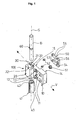
- eine Explosionsansicht eines weiteren Ausführungsbeispiels eines erfindungsgemäßen Flügelbandteils zur Horizontalverstellung in einer perspektivischen Darstellung;
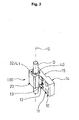
- Fig. 8
- das Ausführungsbeispiel aus
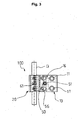
Fig. 7 im montierten Zustand in einer perspektivischen Darstellung und - Fig. 9
- das Ausführungsbeispiel aus
Fig. 7 im montierten Zustand in einer Draufsicht von hinten, wobei nichtsichtbare Linien gestrichelt dargestellt sind.
- Fig. 1
- an exploded view of a wing hinge part according to the invention for horizontal adjustment in a perspective view;
- Fig. 2
- the embodiment
Fig. 1 in the assembled state in a perspective view; - Fig. 3
- the embodiment
Fig. 1 in the assembled state in a plan view from the front, with non-visible lines are shown in dashed lines; - Fig. 4
- an exploded view of another embodiment of a wing hinge part according to the invention for horizontal adjustment in a perspective view;
- Fig. 5
- the embodiment
Fig. 4 in the assembled state in a perspective view; - Fig. 6
- the embodiment
Fig. 4 in the mounted state in a plan view from behind, with non-visible lines are shown in dashed lines; - Fig. 7
- an exploded view of another embodiment of a wing hinge part according to the invention for horizontal adjustment in a perspective view;
- Fig. 8
- the embodiment
Fig. 7 in the assembled state in a perspective view and - Fig. 9
- the embodiment
Fig. 7 in the mounted state in a plan view from behind, with non-visible lines are shown in dashed lines.
Das Flügelbandteil 100 umfasst ein horizontal vorspringendes, wulstartiges Scharnierteil 20 mit einer in Verstellrichtung V ovalen Bandbolzenbohrung 30, von welchem einstückig seitlich an ein plattenförmiges Befestigungsteil 10 auslädt, welches dazu bestimmt ist, mit seiner ebenen Rückseite an der ebenen Vorderseite des nicht dargestellten Flügels anzuliegen.The
Das Befestigungsteil 10 weist zwei durch es in Richtung des Flügels hindurchgehende Bohrungen 11 auf, mittels derer es durch nicht dargestellten Schrauben an dem Flügel befestigt wird.The
Das Scharnierteil 20 weist auf der Innenseite 31 der Bandbolzenbohrung 30 zwei sich Längs in Richtung der Scharnierachse S erstreckende Nuten 32 auf, die für die entsprechende Aufnahme der Vorsprünge 41 auf der Außenseite der den Bandbolzen B umgebenden Hülse 40 bildet.The
Die Hülse 40 weist auf der gegenüberliegenden Außenseite jeweils im oberen und unteren Bereich eine Bohrung oder Aussparung 42 auf. Das Scharnierteil 20 weist ferner an seiner in Richtung der Vorderseite des nicht dargestellten Flügels gerichteten Wand jeweils im oberen und unteren Bereich ein Langloch 33 auf, dessen Längserstreckung sich in Verstellrichtung erstreckt und mit der jeweiligen Aussparung 42 der Hülse 40 korrespondiert.The
Auf der Rückseite des plattenförmigen Befestigungsteils 10, also auf der zur Vorderseite des Flügels hingewandten Seite befindet sich ein sockelartiger Vorsprung 14, in dessen Bereich sich die Befestigungsbohrungen 11 befinden. Im daneben liegenden Bereich 15, der im Einbauzustand von der Vorderfläche des Flügels um die Tiefe des Vorsprungs 14 absteht, und zu einem geringen Teil im angrenzenden Vorsprung 14 ist in einer Aussparung 16 ein Verstellelement 50 angeordnet. Das Verstellelement 50 besitzt etwa die Form eines in Richtung des Scharnierteils 20 offenen "C" und ist über eine Exzenteranordnung 51 in Verstellrichtung innerhalb der Aussparung 16 parallel zur Vorderseite des Flügels horizontal verlagerbar. Die Exzenteranordnung 51 greift zum einen in ein senkrecht zur Verstellrichtung ausgerichtetes Langloch 54 im Verstellelement 51 und andererseits in eine durchgehende Bohrung 13 im Befestigungsteil 10 ein, so dass die Exzenteranordnung 51 im Einbauzustand von Außen betätigt werden kann, um das Verstellelement 50 innerhalb der Aussparung 16 in Verstellrichtung V zu verlagern. Dabei greift das Verstellelement 50 mit je einem an den "Armen" 55 des "C" vorgesehenen Dorn 52 durch das jeweilige Langloch 33 in der Wand des Scharnierteils 30 in die Bohrungen 42 der Hülse 40 ein, die den Bandbolzen B umgibt.On the back of the plate-shaped
Eine Bewegung des Verstellelements 50 wird über die "Arme" bzw. Dorne 52 an die Hülse 40 und somit an den Bandbolzen B weitergegeben. Dabei führt die Hülse mit dem Bandbolzen innerhalb der ovalen Bandbolzenbohrung 30 eine Drehbewegung durch. Da die Hülse bzw. der Bandbolzen an zwei Stellen (Dorne 52) angelenkt wird, ist ein Verkanten verhindert und eine Bewegung mit exakter Beibehaltung der Ausrichtung des Bandbolzens ermöglicht.A movement of the adjusting
Es wird also in einfacher Weise eine Drehbewegung an einem leichtzugänglichen Element in eine horizontale Verstellung des Bandbolzens "umgelenkt", ohne das der Bandbolzen eine besondere Ausgestaltung erfahren muss.It is thus in a simple manner a rotational movement of an easily accessible element in a horizontal adjustment of the hinge pin "deflected" without the hinge pin must be given a special design.
Die Dorne 52 sind über Bohrungen 53 mit den Armen 55 des Verstellelements 50 verbunden. Das Verstellelement 50 ist über nicht dargestellte Schrauben, die entsprechende in Verstellrichtung V längliche Bohrungen 12 im Befestigungsteil 10 durch- und in korrespondierende Bohrungen 56 im Verstellelement 50 eingreifen, befestigt.The
Der Bandbolzen B weist in seiner Längserstreckung etwa mittig positioniert eine umlaufende Nut 60 auf, in die eine Madenschraube 61 (vgl.
Die Vorderseite des Befestigungsteils 10 wird üblicherweise mit einer in den
In den weiteren Figuren sind Varianten eines erfindungsgemäßen Bandes dargestellt, wobei sich entsprechende Teile mit jeweils um 100 (
Das in den
Konstruktiv wird nachfolgend nur auf die Unterschiede zum Flügelbandteil aus den
Das Scharnierteil 120 weist eine Bandbolzenbohrung 130 auf, die im Gegensatz zum Bandteil 100 nicht in Verstellrichtung V oval ausgeführt ist und keine sich Längs in Richtung der Scharnierachse S erstreckende Geradführung aufweist, sondern einen etwa halbkreisförmigen Querschnitt, so daß von oben und unten in die Bandbolzenbohrung 130 eingesteckte Führungsbuchsen 140 gegen Verdrehen festgelegt sind. Die Buchsen 140 weisen eine Bohrung 143 auf, die in Verstellrichtung V lang gestreckt ausgebildet ist und in die vom Bandbolzen B durchgriffen wird. Die Buchsen 140 dienen der Führung des Bandbolzens bei dessen Verstellung.The
Auf der Rückseite des plattenförmigen Befestigungsteils 110, also auf der zur Vorderseite des Flügels hingewandten Seite befindet in einer Aussparung 116 ein Verstellelement 150. Das Verstellelement 150 besitzt etwa die Form eines "L" und erstreckt sich mit einem Schenkel 155 in die Bandbolzenbohrung 130 des Scharnierteils 120. Die Aussparung 116 öffnet also von hinten die Bandbolzenbohrung 130, so dass das Verstellelement 150 in diese durch eine Öffnung 133 hineinragen kann. Das Verstellelement 150 besitzt zur Übertragung der Verstellbewegung auf den Bandbolzen B keine Dorne, sondern sich entlang der Scharnierachse S erstreckende Bohrungen 153 in den Schenkeln 155, die von dem Bandbolzen B im Einbauzustand durchgriffen werden. Der Bandbolzen B wird von den Bohrungen 153 geführt, so dass wiederum eine Verlagerung unter exakter Beibehaltung seiner Ausrichtung gewährleistet ist.On the back of the plate-shaped
Das Verstellelement ist ebenfalls über eine Exzenteranordnung 151 in Verstellrichtung innerhalb der Aussparung 116 parallel zur Vorderseite des Flügels horizontal verlagerbar. Die Exzenteranordnung 151 greift zum einen in ein senkrecht zur Verstellrichtung ausgerichtetes Langloch 154 im Verstellelement 150 und andererseits in eine durchgehende Bohrung 113 im Befestigungsteil 110 ein, so dass die Exzenteranordnung 151 im Einbauzustand von Außen betätigt werden kann, um das Verstellelement 150 innerhalb der Aussparung 116 in Verstellrichtung V zu verlagern. Dabei ragt das Verstellelement 150 mit seinen Schenkeln 155 durch die Öffnung 133 in der Wand des Scharnierteils 130 in die Bandbolzenbohrung hinein und umgreift mit je einem der in den Schenkeln 155 des "L" vorgesehenen Bohrung 153 den Bandbolzen B und verlagert diesen in Verstellrichtung V, wobei er durch die Bohrungen 143 der Buchsen 140 geführt wird.The adjusting element is also displaceable horizontally via an eccentric 151 in the adjustment direction within the
Der Bandbolzen B weist wie in der ersten Ausführungsform (
Das in den
Wesentlichster Unterschied ist der "Antrieb" für die Verlagerung des Verstellelements 250, welche nicht über eine Exzenteranordnung, sondern mittels einer Gewindespindel 251 durchgeführt wird.The most important difference is the "drive" for the displacement of the adjusting
Zur Aufnahme der Spindel 251 ist im Bereich des Vorsprungs 214, der nunmehr als abnehmbarer Teil ausgestaltet ist, eine sich in Verstellrichtung V erstrechende, im Querschnitt halbkreisförmige Nut 257 vorgesehen. Die Nut 257 weist eine verbreiterte Stelle 258 zur Aufnahme und Festlegung des Kopfes der Spindel 251 auf. Damit die Spindel 251 nicht "herausfallen" kann, wird die Nut 257 von einem abnehmbaren Teil 214' des Vorsprungs 214 im Einbauzustand abgedeckt. Die Spindel 251 erstreckt sich dabei in den Bereich der Aussparung 216, wo sie in eine korrespondierende Gewindebohrung 253 im Verstellelement 250 eingreift. Bei einer Drehung der Spindel 251 wird also das Verstellelement 250 in der Aussparung 216 in Verstellrichtung verlagert und gibt diese Bewegung an den Bandbolzen wie bei der vorhergehenden Ausführungsform der
Bei der in den
Claims (9)
- Hinge (100) for doors, windows or the like for the articulated connection of a leaf of the door, a sash of the window or the like about an articulation axis (S) on a frame, comprising:- a frame hinge part to be fastened by its rear side to the frame of the door, of the window or the like via a fastening part;- a leaf/sash part (100, 200, 300) to be fastened by its rear side to the leaf of the door, sash of the window or the like via a fastening part (10, 110, 210);- articulation parts (20, 120, 220) of the hinge parts (100, 200, 300), which articulation parts are arranged above one another and into which at least one hinge pin (B), which defines the vertical articulation axis (S), engages in a hinge pin bore (30, 130, 230); and- an adjusting element (50, 150, 250) which acts on the hinge pin (B) within the hinge pin bore (30, 130, 230) for adjustment purposes, wherein the adjustment occurs in the horizontal, parallel to the plane running through the frame or leaf/sash, in the assembled state,characterized in that the adjusting element (50, 150, 250) is arranged in a recess (16, 116, 216), which is situated on the rear side of at least one of the fastening parts, such that it can be displaced in the horizontal adjustment direction (V).
- Hinge according to Claim 1, characterized in that the adjusting element (150, 250) is designed in such a way that it acts directly on the hinge pin (B).
- Hinge according to Claim 1, characterized in that the adjusting element (50) is designed in such a way that it acts indirectly on the hinge pin (B).
- Hinge according to one of Claims 1-3,
characterized in that it comprises a guide (40, 140, 240) which guides and at least partially surrounds the hinge pin (B). - Hinge according to Claim 4, characterized in that the guide is designed as at least one bush (140, 240) which engages in the hinge pin bore (130, 230) and which has an oblong hole (143, 243) whose longitudinal extent extends in the adjustment direction.
- Hinge according to Claim 4, characterized in that the guide is designed as a sleeve (40) which surrounds the hinge pin (B) and on which the adjusting element (50) acts.
- Hinge according to Claim 6, characterized in that the sleeve (40) is provided on its outer side with at least one projection (41) which engages in at least one corresponding groove (32) on the inner side (31) of the hinge pin bore (30) in such a way that, during an adjustment of the adjusting element (50), the sleeve inside the hinge pin bore (30), which has the shape of an oblong hole in the adjustment direction (V), performs a rotary movement.
- Hinge according to one of the preceding claims,
characterized in that the adjusting element (50, 150) comprises an eccentric arrangement (51, 151) for producing the adjusting movement. - Hinge according to one of the preceding claims,
characterized in that the adjusting element (250) comprises an adjusting spindle (251) for producing the adjusting movement.
Priority Applications (1)
| Application Number | Priority Date | Filing Date | Title |
|---|---|---|---|
| PL04015108T PL1512817T3 (en) | 2003-09-03 | 2004-06-28 | Fitting for doors, windows or the like |
Applications Claiming Priority (2)
| Application Number | Priority Date | Filing Date | Title |
|---|---|---|---|
| DE20313635U DE20313635U1 (en) | 2003-09-03 | 2003-09-03 | Tape for doors, windows or the like |
| DE20313635U | 2003-09-03 |
Publications (3)
| Publication Number | Publication Date |
|---|---|
| EP1512817A2 EP1512817A2 (en) | 2005-03-09 |
| EP1512817A3 EP1512817A3 (en) | 2007-03-14 |
| EP1512817B1 true EP1512817B1 (en) | 2009-11-04 |
Family
ID=34072145
Family Applications (1)
| Application Number | Title | Priority Date | Filing Date |
|---|---|---|---|
| EP04015108A Expired - Lifetime EP1512817B1 (en) | 2003-09-03 | 2004-06-28 | Fitting for doors, windows or the like |
Country Status (3)
| Country | Link |
|---|---|
| EP (1) | EP1512817B1 (en) |
| DE (2) | DE20313635U1 (en) |
| PL (1) | PL1512817T3 (en) |
Families Citing this family (4)
| Publication number | Priority date | Publication date | Assignee | Title |
|---|---|---|---|---|
| DE202006002236U1 (en) | 2006-02-10 | 2007-06-21 | Dr. Hahn Gmbh & Co. Kg | Tape for doors, windows or the like |
| GB0912447D0 (en) * | 2009-07-17 | 2009-08-26 | Avocet Hardware Ltd | Adjustable hinge |
| IT1398134B1 (en) * | 2009-07-24 | 2013-02-14 | Co A R S R L | ADJUSTABLE HINGES FOR WINDOWS |
| DE102018111157B3 (en) | 2018-05-09 | 2019-07-04 | Dr. Hahn Gmbh & Co. Kg | Band for pivotable about a hinge axis attachment of a wing to a frame |
Family Cites Families (3)
| Publication number | Priority date | Publication date | Assignee | Title |
|---|---|---|---|---|
| DE3642127A1 (en) * | 1986-12-10 | 1988-06-23 | Hahn Gmbh & Co Kg Dr | BAND FOR DOORS, WINDOWS AND THE LIKE |
| DE29721078U1 (en) * | 1997-11-28 | 1999-04-01 | Niemann, Hans Dieter, 50169 Kerpen | Door or window hinge |
| GB0016624D0 (en) * | 2000-07-07 | 2000-08-23 | Window Fab & Fixing Supplies | Hinge |
-
2003
- 2003-09-03 DE DE20313635U patent/DE20313635U1/en not_active Expired - Lifetime
-
2004
- 2004-06-28 PL PL04015108T patent/PL1512817T3/en unknown
- 2004-06-28 EP EP04015108A patent/EP1512817B1/en not_active Expired - Lifetime
- 2004-06-28 DE DE502004010315T patent/DE502004010315D1/en not_active Expired - Fee Related
Also Published As
| Publication number | Publication date |
|---|---|
| PL1512817T3 (en) | 2010-04-30 |
| DE502004010315D1 (en) | 2009-12-17 |
| EP1512817A2 (en) | 2005-03-09 |
| DE20313635U1 (en) | 2005-01-13 |
| EP1512817A3 (en) | 2007-03-14 |
Similar Documents
| Publication | Publication Date | Title |
|---|---|---|
| EP2369107B1 (en) | Hinge, in particular for plastic doors and plastic windows | |
| EP0285229B2 (en) | Adjustable hinge, especially for doors | |
| EP1577476B1 (en) | Hinge for pivotingly mounting of a door or window on a frame | |
| EP1437467B1 (en) | Hinge for doors or windows | |
| EP2754813B1 (en) | Hinge, in particular for plastic doors and windows | |
| EP1017920B1 (en) | Brace for pivotally mounting a wing of a window or door | |
| EP2503084B1 (en) | Adjustable hinge | |
| EP2245251B1 (en) | Corner hinge for a window, a door or the like | |
| EP1512817B1 (en) | Fitting for doors, windows or the like | |
| EP0478639A1 (en) | Hinge. | |
| EP0652345B1 (en) | Adjustable hinge for doors or windows | |
| DE3407174C2 (en) | ||
| EP1215357B1 (en) | Hinge assembly for doors, windows or the like | |
| EP0837206B1 (en) | Door hinge for swingingly supporting a door leaf from a door frame | |
| DE202007011982U1 (en) | Adjustable band | |
| CH690504A5 (en) | Hinge device, particularly for folding sliding door or window, involves running mechanism guided in upper or lower running rail connected with upright determining hinge axis | |
| DE202005009745U1 (en) | fitting assembly | |
| EP1106763B1 (en) | Hinge for doors, windows or like that | |
| DE19642638A1 (en) | Hinge | |
| EP0340455B2 (en) | Pivot bearing for the connection of two wings of a window, door or the like | |
| DE20316622U1 (en) | Tape for doors, windows or the like | |
| EP3205803B1 (en) | Device for damping and limiting an opening movement | |
| DE19918283A1 (en) | Door or window hinge, contains hinge pin receiving part adjustable mounted between arms of U shaped hinge part secured to window or door leaf | |
| DE2551316A1 (en) | Two side window stay mechanism - has adjusting element in hinge arm acting on lug protruding from stay arm end | |
| DE29816395U1 (en) | Adjustable hinge for windows or doors |
Legal Events
| Date | Code | Title | Description |
|---|---|---|---|
| PUAI | Public reference made under article 153(3) epc to a published international application that has entered the european phase |
Free format text: ORIGINAL CODE: 0009012 |
|
| AK | Designated contracting states |
Kind code of ref document: A2 Designated state(s): AT BE BG CH CY CZ DE DK EE ES FI FR GB GR HU IE IT LI LU MC NL PL PT RO SE SI SK TR |
|
| AX | Request for extension of the european patent |
Extension state: AL HR LT LV MK |
|
| PUAL | Search report despatched |
Free format text: ORIGINAL CODE: 0009013 |
|
| AK | Designated contracting states |
Kind code of ref document: A3 Designated state(s): AT BE BG CH CY CZ DE DK EE ES FI FR GB GR HU IE IT LI LU MC NL PL PT RO SE SI SK TR |
|
| AX | Request for extension of the european patent |
Extension state: AL HR LT LV MK |
|
| 17P | Request for examination filed |
Effective date: 20070907 |
|
| AKX | Designation fees paid |
Designated state(s): BE DE FR IT PL TR |
|
| 17Q | First examination report despatched |
Effective date: 20071029 |
|
| GRAP | Despatch of communication of intention to grant a patent |
Free format text: ORIGINAL CODE: EPIDOSNIGR1 |
|
| GRAS | Grant fee paid |
Free format text: ORIGINAL CODE: EPIDOSNIGR3 |
|
| GRAA | (expected) grant |
Free format text: ORIGINAL CODE: 0009210 |
|
| AK | Designated contracting states |
Kind code of ref document: B1 Designated state(s): BE DE FR IT PL TR |
|
| REF | Corresponds to: |
Ref document number: 502004010315 Country of ref document: DE Date of ref document: 20091217 Kind code of ref document: P |
|
| REG | Reference to a national code |
Ref country code: PL Ref legal event code: T3 |
|
| PLBE | No opposition filed within time limit |
Free format text: ORIGINAL CODE: 0009261 |
|
| STAA | Information on the status of an ep patent application or granted ep patent |
Free format text: STATUS: NO OPPOSITION FILED WITHIN TIME LIMIT |
|
| 26N | No opposition filed |
Effective date: 20100805 |
|
| BERE | Be: lapsed |
Owner name: DR. HAHN G.M.B.H. & CO. KG Effective date: 20100630 |
|
| REG | Reference to a national code |
Ref country code: FR Ref legal event code: ST Effective date: 20110228 |
|
| PG25 | Lapsed in a contracting state [announced via postgrant information from national office to epo] |
Ref country code: IT Free format text: LAPSE BECAUSE OF NON-PAYMENT OF DUE FEES Effective date: 20100628 |
|
| PG25 | Lapsed in a contracting state [announced via postgrant information from national office to epo] |
Ref country code: DE Free format text: LAPSE BECAUSE OF NON-PAYMENT OF DUE FEES Effective date: 20110101 |
|
| PG25 | Lapsed in a contracting state [announced via postgrant information from national office to epo] |
Ref country code: FR Free format text: LAPSE BECAUSE OF NON-PAYMENT OF DUE FEES Effective date: 20100630 |
|
| PG25 | Lapsed in a contracting state [announced via postgrant information from national office to epo] |
Ref country code: BE Free format text: LAPSE BECAUSE OF NON-PAYMENT OF DUE FEES Effective date: 20100630 |
|
| REG | Reference to a national code |
Ref country code: PL Ref legal event code: LAPE |
|
| PG25 | Lapsed in a contracting state [announced via postgrant information from national office to epo] |
Ref country code: PL Free format text: LAPSE BECAUSE OF NON-PAYMENT OF DUE FEES Effective date: 20100628 |
|
| PG25 | Lapsed in a contracting state [announced via postgrant information from national office to epo] |
Ref country code: TR Free format text: LAPSE BECAUSE OF FAILURE TO SUBMIT A TRANSLATION OF THE DESCRIPTION OR TO PAY THE FEE WITHIN THE PRESCRIBED TIME-LIMIT Effective date: 20091104 |