EP1512814A2 - Motor vehicle door lock system and door handle - Google Patents
Motor vehicle door lock system and door handle Download PDFInfo
- Publication number
- EP1512814A2 EP1512814A2 EP04019668A EP04019668A EP1512814A2 EP 1512814 A2 EP1512814 A2 EP 1512814A2 EP 04019668 A EP04019668 A EP 04019668A EP 04019668 A EP04019668 A EP 04019668A EP 1512814 A2 EP1512814 A2 EP 1512814A2
- Authority
- EP
- European Patent Office
- Prior art keywords
- motor vehicle
- vehicle door
- actuating device
- door lock
- handle
- Prior art date
- Legal status (The legal status is an assumption and is not a legal conclusion. Google has not performed a legal analysis and makes no representation as to the accuracy of the status listed.)
- Granted
Links
Images
Classifications
-
- E—FIXED CONSTRUCTIONS
- E05—LOCKS; KEYS; WINDOW OR DOOR FITTINGS; SAFES
- E05B—LOCKS; ACCESSORIES THEREFOR; HANDCUFFS
- E05B81/00—Power-actuated vehicle locks
- E05B81/12—Power-actuated vehicle locks characterised by the function or purpose of the powered actuators
- E05B81/14—Power-actuated vehicle locks characterised by the function or purpose of the powered actuators operating on bolt detents, e.g. for unlatching the bolt
-
- E—FIXED CONSTRUCTIONS
- E05—LOCKS; KEYS; WINDOW OR DOOR FITTINGS; SAFES
- E05B—LOCKS; ACCESSORIES THEREFOR; HANDCUFFS
- E05B81/00—Power-actuated vehicle locks
- E05B81/54—Electrical circuits
- E05B81/64—Monitoring or sensing, e.g. by using switches or sensors
- E05B81/76—Detection of handle operation; Detection of a user approaching a handle; Electrical switching actions performed by door handles
- E05B81/78—Detection of handle operation; Detection of a user approaching a handle; Electrical switching actions performed by door handles as part of a hands-free locking or unlocking operation
-
- E—FIXED CONSTRUCTIONS
- E05—LOCKS; KEYS; WINDOW OR DOOR FITTINGS; SAFES
- E05B—LOCKS; ACCESSORIES THEREFOR; HANDCUFFS
- E05B81/00—Power-actuated vehicle locks
- E05B81/54—Electrical circuits
- E05B81/64—Monitoring or sensing, e.g. by using switches or sensors
- E05B81/76—Detection of handle operation; Detection of a user approaching a handle; Electrical switching actions performed by door handles
- E05B81/77—Detection of handle operation; Detection of a user approaching a handle; Electrical switching actions performed by door handles comprising sensors detecting the presence of the hand of a user
-
- Y—GENERAL TAGGING OF NEW TECHNOLOGICAL DEVELOPMENTS; GENERAL TAGGING OF CROSS-SECTIONAL TECHNOLOGIES SPANNING OVER SEVERAL SECTIONS OF THE IPC; TECHNICAL SUBJECTS COVERED BY FORMER USPC CROSS-REFERENCE ART COLLECTIONS [XRACs] AND DIGESTS
- Y10—TECHNICAL SUBJECTS COVERED BY FORMER USPC
- Y10T—TECHNICAL SUBJECTS COVERED BY FORMER US CLASSIFICATION
- Y10T292/00—Closure fasteners
- Y10T292/08—Bolts
- Y10T292/1043—Swinging
- Y10T292/1075—Operating means
- Y10T292/1082—Motor
Definitions
- the present invention relates to a motor vehicle door locking system according to the preamble of claim 1 and a door handle for a motor vehicle door according to the preamble of claim 16.
- motor vehicle door locking systems is usually a door inside handle mechanically connected to an associated motor vehicle door lock.
- an associated motor vehicle door lock When pulling the inside door handle - so when pressing - is due to the Inertia and / or stiffness of the mechanism unintentional opening the associated motor vehicle door unlikely.
- the present invention is based on the object, a motor vehicle door locking system and specify an inside door handle, wherein an unintentional Opening an associated motor vehicle door when using an electric activated motor vehicle door lock, so a so-called electric lock, can be avoided.
- An essential idea of the present invention resides in a first Actuating device, such as a button or sensor, for electrical control the motor vehicle door lock addition to a second actuator to provide, with unlocking and / or opening the associated motor vehicle door lock only with simultaneous actuation of both controls and / or prior unlocking of the first actuator by Operation of the second actuator is enabled. This avoids that an unwanted actuation of the first actuating device to a unintentional unlocking and / or opening the motor vehicle door lock and thus the associated motor vehicle door can lead.
- a first Actuating device such as a button or sensor
- the two actuating devices on a door inside handle on different, in particular arranged facing away from each other so that different hand areas and / or fingers used to operate the two actuators Need to become. Consequently, inadvertent operation of one of the two, for example, to the vehicle interior facing controls - For example, by an arm or leg of a vehicle occupant-not for unintentional unlocking and / or opening of the associated motor vehicle door lock, as a prior or simultaneous operation of the other Actuator is not done.
- the actuating devices designed and / or arranged such that a grasping a Door inside handle for their operation and thus for unlocking or opening a associated motor vehicle door lock is required. This will ensure that an operator when unlocking or opening the vehicle door the Inside door handle holds in the hand and consequently on a possible opening motor vehicle door is prepared.
- the additionally provided, second actuator also act such that only by their operation, the first actuator is unlocked, this being done mechanically and / or electrically can.
- actuation is in the present invention, first in a tighter sense than mechanical action of an operator or a Vehicle occupants, in particular with a hand or a finger, on a button, Switch or the like. Or a deformation of a handle portion by the operator to understand. In a broader sense, however, this is also a Approaching - for example to a sensor or a door handle - and / or a Touching a door handle portion or the like to understand, the approach or touch can be detected and evaluated as an operation.
- the use of the proposed solution leads to a motor vehicle door locking system with a passive entry function for unlocking the motor vehicle door lock from the outside to very special advantages.
- the unlocking of the motor vehicle door lock starts in such a system with a start-up interval to activate the system as the operator approaches. This is followed by an authorization check interval to alert the operator to his To verify permission.
- the operator enters, for example Remote control module with it, with the appropriate signals are exchanged can.
- the action interval follows, in which the actual unlocking is performed in the motor vehicle door lock. After completion of the action interval is the motor vehicle door lock openable.
- one of the actuating devices now used to start the start-up interval described above is preferably as a proximity switch educated.
- the subsequent operation of the other actuator then preferably leads to the motor vehicle door lock being opened, if the action interval, ie the unlocking, is completed.
- the action interval ie the unlocking
- Operation with two actuators makes it possible to wait for the operator during the start-up interval, of the authorization check interval and the action interval. This is especially true when the starting the starting interval actuator designed as a proximity switch.
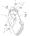
- Fig. 1 shows a schematic representation of a motor vehicle 1 with one only partially indicated motor vehicle door closing system 2, in particular several Motor vehicle door locks 3, preferably for motor vehicle side doors 4, a motor vehicle tailgate or the like, has, wherein the installation positions the motor vehicle door locks 3 in Fig. 1 indicated schematically by arrows are.
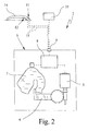
- each motor vehicle door lock 3 is motorized, in particular electromotive, unlockable and lockable and / or openable, as in schematic representation of the proposed door closing system 2 according to Fig. 2 shown.
- the motor vehicle door lock 3 has in the illustrated example an actuator or drive 5, which is a conventional locking mechanism, here a pawl. 6 acts, which is a backup of an associated rotary latch 7 of the motor vehicle door lock 3 serves. It goes without saying that other types of Locking mechanisms are used.
- the actuator 5 in particular has an electric motor. Instead of the preferred one Training as an electric lock, the actuator 5, however, for example also act pneumatically or hydraulically or be actuated. In any case the motor vehicle door lock 3 preferably electrically controlled or controlled.
- the motor vehicle door lock 3 has a control unit 8 for controlling or Actuation of the actuator 5 and / or for detection, possibly also evaluation of Activation signals.
- the motor vehicle door lock 3 or its control unit 8 is connected via a plug connection 9 to a preferably central control device 10 of the motor vehicle 1 or of the motor vehicle door locking system 2 connected.
- the motor vehicle door lock 3 are a first actuator 11 and associated with a second actuator 12, in the representation example - As indicated by the dotted lines 13 - electrically directly connected to the motor vehicle door lock 3 and its control unit 8 are.
- the actuators 11, 12 optionally also to the Control device 10 may be connected. In any case, serve the controls 11, 12 an electrical control of the associated motor vehicle door lock Third
- the actuators 11, 12 a door inside handle 14 assigned, in particular arranged and / or integrated into this, as indicated in Fig. 2.
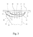
- Other aspects of the proposed door handle 14 and the motor vehicle door closing system 2 will be described below Based on the enlarged schematic representation of the door inner handle 14 according to Fig. 3 explained in more detail.
- the inside door handle 14 is on the inside of the door 15 on the associated motor vehicle door 4, which are shown schematically in Fig. 3 and only partially is.
- Fig. 3 is a hand 16 with fingers 17 of an operator, not shown indicated by dash-dotted lines, the hand 16 the door inner handle 14 at least partially engages and with the fingers 17 in an inner region 18 of the door inner handle 14 engages.
- the first actuator 11 is preferably in the illustrated example designed as a button 19, for example, by means of the thumb 20 of the hand 16 is actuated, as indicated in Fig. 3.
- the second actuator 12 has in the illustrated example a Sensor 21, which is an approximation and / or touch of the hand 16 and the Finger 17, in particular an engagement of the fingers 17 in the interior 18th and / or embracing the inside door handle 14 can capture.
- a Sensor 21 which is an approximation and / or touch of the hand 16 and the Finger 17, in particular an engagement of the fingers 17 in the interior 18th and / or embracing the inside door handle 14 can capture.
- the sensor 21 may, for example, also Inductive, piezoelectric or optical work.
- the senor 21 is designed as a switch or evaluable switching, so that an operation can be detected.
- An actuation is especially then when the hand 16 or the fingers 17, the door inner handle 14 at least partially and / or partially, touch and / or in the interior 18 intervene.
- a corresponding evaluation of the detected signals is within the second Actuating device 12, in the sensor 21, inside the door handle 14, in the control unit 8 and / or in the control device 10 possible.
- the senor 21 as a proximity switch and / or touch switch educated. Instead of the sensor 21, however, can also be a button 19 or another suitable switching device or the like for the second actuating device 12 are used.
- the button 19 may, if necessary, for the first actuator 11 also a sensor 21 or other suitable switching device or Like. Be used.
- the associated motor vehicle door lock 3 unlocks or opens.
- This can be done by appropriate interconnection the actuators 11, 12 and / or corresponding evaluation of from the actuators 11, 12 output actuating signals -
- this evaluation can also be integrated into the inside door handle 14 be; In this case, it is a "smart" inside door handle 14th
- Actuation of the two actuators 11, 12 can - in particular in the representation example - be provided that first actuation of the second actuator 12 - ie in particular an intervention in the door inner handle 14 and its interior 18 -. must be done and then at subsequent Actuation of the first actuating device 11 - in the representation example the button 19 with the thumb 20 - unlocking or opening the associated motor vehicle door lock 3 takes place or is possible.
- both actuators 11, 12 each have a button 19 and / or a sensor 21 and / or a suitable switch or the like.
- the pointing on the vehicle interior towards Side or top of the door inner handle 14 arranged or integrated into this first actuating device 11 designed such that a mechanical actuation - In the illustrated example of the button 19 - or a deformation - so a relatively strong mechanical action - the operator to operate is required.
- the second actuator 12 is preferably on a remote side or to the interior of the door inner handle 14 at least partially limited 18 facing side or bottom of the door inner handle 14 is arranged or integrated therein and designed such that an approach or touch - So at most low mechanical impact of an operator-as Operation is sufficient. So on the one hand, the desired backup against Unintentional unlocking or opening the vehicle door 3 and on the other hand a simple operation, as the operator is only on the active pressing the first actuator 11 must focus allows.
- the proposed solution is basically also in an outside door handle or used in other handling elements.
- the second actuator 12 also mechanically on the first actuator 11 - for example, as a mechanical Lock - act.
- the motor vehicle door locking system 2 with a passive entry function for unlocking the motor vehicle door lock 3 equipped.
- a passive entry function for unlocking the motor vehicle door lock 3 equipped.
- the startup interval is now preferably by the operation of at least one of the two actuating devices 11, 12 started.
- a particularly compact arrangement can be achieved in that the Actuation of the first actuator 11, the start-up interval starts and that the actuation of the second actuator 12, the opening of the Motor vehicle door lock 3 causes, if the action interval, ie the unlocking of the motor vehicle door lock 3, is completed.
- the second actuating device 12 is here preferably designed as a button.
Landscapes
- Lock And Its Accessories (AREA)
Abstract
Es werden ein Kraftfahrzeug-Türschließsystem und ein Türgriff vorgeschlagen.
Um ein Entriegeln oder Öffnen eines elektrisch angesteuerten Kraftfahrzeug-Türschlosses
durch unbeabsichtigtes Betätigen einer ersten Betätigungseinrichtung
zu verhindern, ist eine zweite Betätigungseinrichtung vorgesehen, wobei
zum Entriegeln bzw. Öffnen des Kraftfahrzeug-Türschlosses und damit der zugeordneten
Kraftfahrzeugtür eine gleichzeitige Betätigung beider Betätigungseinrichtungen
erforderlich ist.

Description
Die vorliegende Erfindung betrifft ein Kraftfahrzeug-Türschließsystem gemäß
dem Oberbegriff des Anspruchs 1 sowie einen Türgriff für eine Kraftfahrzeugtür
gemäß dem Oberbegriff des Anspruchs 16.The present invention relates to a motor vehicle door locking system according to
the preamble of
Bei Kraftfahrzeug-Türschließsystemen wird bisher üblicherweise ein Türinnengriff mechanisch mit einem zugeordneten Kraftfahrzeug-Türschloß verbunden. Beim Ziehen des Türinnengriffs - also bei der Betätigung - ist aufgrund der Trägheit und/oder Schwergängigkeit der Mechanik ein unbeabsichtigtes Öffnen der zugeordneten Kraftfahrzeug-Tür unwahrscheinlich.In motor vehicle door locking systems is usually a door inside handle mechanically connected to an associated motor vehicle door lock. When pulling the inside door handle - so when pressing - is due to the Inertia and / or stiffness of the mechanism unintentional opening the associated motor vehicle door unlikely.
Der Einsatz eines Elektroschlosses als Kraftfahrzeug-Türschloß mit einem Taster zum elektrischen Ansteuern und Entriegeln oder Öffnen ist bereits vorgeschlagen worden. Hierbei besteht jedoch gegenüber der mechanischen Ansteuerung ein wesentlich erhöhtes Risiko, daß ein ungewolltes Betätigen des Tasters oder einer sonstigen Betätigungseinrichtung zu einem unbeabsichtigten Öffnen der zugeordneten Kraftfahrzeugtür führt.The use of an electric lock as a motor vehicle door lock with a button for electrical control and unlock or open is already proposed Service. In this case, however, there is an opposite to the mechanical control significantly increased risk that an accidental actuation of the button or a other actuator to an unintentional opening of the associated Motor vehicle door leads.
Der vorliegenden Erfindung liegt die Aufgabe zugrunde, ein Kraftfahrzeug-Türschließsystem und einen Türinnengriff anzugeben, wobei ein ungewolltes Öffnen einer zugeordneten Kraftfahrzeugtür bei Verwendung eines elektrisch angesteuerten Kraftfahrzeug-Türschlosses, also eines sogenannten Elektroschlosses, vermieden werden kann.The present invention is based on the object, a motor vehicle door locking system and specify an inside door handle, wherein an unintentional Opening an associated motor vehicle door when using an electric activated motor vehicle door lock, so a so-called electric lock, can be avoided.
Die obige Aufgabe wird durch ein Kraftfahrzeug-Türschließsystem gemäß Anspruch
1 oder einen Türgriff gemäß Anspruch 16 gelöst. Vorteilhafte Weiterbildungen
sind Gegenstand der Unteransprüche.The above object is achieved by a motor vehicle door locking system according to
Eine wesentliche Idee der vorliegenden Erfindung liegt darin, über eine erste Betätigungseinrichtung, wie einen Taster oder Sensor, zur elektrischen Ansteuerung des Kraftfahrzeug-Türschlosses hinaus eine zweite Betätigungseinrichtung vorzusehen, wobei ein Entriegeln und/oder Öffnen des zugeordneten Kraftfahrzeug-Türschlosses nur bei gleichzeitiger Betätigung beider Betätigungseinrichtungen und/oder vorheriger Entsperrung der ersten Betätigungseinrichtung durch Betätigung der zweiten Betätigungseinrichtung ermöglicht wird. So wird vermieden, daß eine ungewollte Betätigung der ersten Betätigungseinrichtung zu einem unbeabsichtigten Entriegeln und/oder Öffnen des Kraftfahrzeug-Türschlosses und damit der zugeordneten Kraftfahrzeugtür führen kann.An essential idea of the present invention resides in a first Actuating device, such as a button or sensor, for electrical control the motor vehicle door lock addition to a second actuator to provide, with unlocking and / or opening the associated motor vehicle door lock only with simultaneous actuation of both controls and / or prior unlocking of the first actuator by Operation of the second actuator is enabled. This avoids that an unwanted actuation of the first actuating device to a unintentional unlocking and / or opening the motor vehicle door lock and thus the associated motor vehicle door can lead.
Gemäß einer besonders bevorzugten Ausführungsform sind die beiden Betätigungseinrichtungen an einem Türinnengriff auf unterschiedlichen, insbesondere voneinander abgewandten Seiten angeordnet, so daß unterschiedliche Handbereiche und/oder Finger zur Betätigung der beiden Betätigungseinrichtungen eingesetzt werden müssen. Folglich führt eine unbeabsichtigte Betätigung einer der beiden, beispielsweise zum Fahrzeuginnenraum weisenden Betätigungseinrichtungen - beispielsweise durch einen Arm oder ein Bein eines Fahrzeuginsassen-nicht zu einem ungewollten Entriegeln und/oder Öffnen des zugeordneten Kraftfahrzeug-Türschlosses, da eine vorherige oder gleichzeitige Betätigung der anderen Betätigungseinrichtung nicht erfolgt ist.According to a particularly preferred embodiment, the two actuating devices on a door inside handle on different, in particular arranged facing away from each other so that different hand areas and / or fingers used to operate the two actuators Need to become. Consequently, inadvertent operation of one of the two, for example, to the vehicle interior facing controls - For example, by an arm or leg of a vehicle occupant-not for unintentional unlocking and / or opening of the associated motor vehicle door lock, as a prior or simultaneous operation of the other Actuator is not done.
Gemäß einer ganz besonders bevorzugte Ausführungsform sind die Betätigungseinrichtungen derart ausgebildet und/oder angeordnet, daß ein Umgreifen eines Türinnengriffs zu deren Betätigung und damit zum Entriegeln bzw. Öffnen eines zugeordneten Kraftfahrzeug-Türschlosses erforderlich ist. So wird sichergestellt, daß eine Bedienperson beim Entriegeln bzw. Öffnen der Kraftfahrzeugtür den Türinnengriff in der Hand hält und folglich auf ein eventuelles Öffnen Kraftfahrzeugtür vorbereitet ist.According to a very particularly preferred embodiment, the actuating devices designed and / or arranged such that a grasping a Door inside handle for their operation and thus for unlocking or opening a associated motor vehicle door lock is required. This will ensure that an operator when unlocking or opening the vehicle door the Inside door handle holds in the hand and consequently on a possible opening motor vehicle door is prepared.
Je nach Ausgestaltung kann die zusätzlich vorgesehene, zweite Betätigungseinrichtung auch derart wirken, daß erst durch ihre Betätigung die erste Betätigungseinrichtung entsperrt wird, wobei dies mechanisch und/oder elektrisch erfolgen kann.Depending on the configuration, the additionally provided, second actuator also act such that only by their operation, the first actuator is unlocked, this being done mechanically and / or electrically can.
Die Bezeichnung "Betätigung" ist bei der vorliegenden Erfindung zunächst in einem engeren Sinne als mechanisches Einwirken einer Bedienperson bzw. eines Fahrzeuginsassen, insbesondere mit einer Hand oder einem Finger, auf einen Taster, Schalter oder dgl. oder ein Verformen eines Griffabschnitts durch die Bedienperson zu verstehen. In einem weiteren Sinne ist hierunter jedoch auch ein Annähern - beispielsweise an einen Sensor bzw. einen Türgriff - und/oder ein Berühren eines Türgriffabschnitts oder dgl. zu verstehen, wobei die Annäherung bzw. Berührung erfaßbar und als Betätigung auswertbar ist. The term "actuation" is in the present invention, first in a tighter sense than mechanical action of an operator or a Vehicle occupants, in particular with a hand or a finger, on a button, Switch or the like. Or a deformation of a handle portion by the operator to understand. In a broader sense, however, this is also a Approaching - for example to a sensor or a door handle - and / or a Touching a door handle portion or the like to understand, the approach or touch can be detected and evaluated as an operation.
Es darf darauf hingewiesen werden, daß die vorschlagsgemäße Lösung auch bei
einem Türaußengriff oder bei sonstigen Handhabungselementen einsetzbar ist.
Dies gilt insbesondere für die Lehre gemäß Anspruch 16, der eigenständige Bedeutung
zukommt und nach der ein Türgriff als solcher beansprucht wird. Dieser
Türgriff kann entsprechend als Türinnengriff, als Türaußengriff oder als sonstiges
Handhabungselement ausgestaltet sein.It may be noted that the proposed solution also in
an outside door handle or other handling elements can be used.
This applies in particular to the teaching according to
Der Einsatz der vorschlagsgemäßen Lösung führt bei einem Kraftfahrzeug-Türschließsystem mit einer Passive-Entry-Funktion zur Entriegelung des Kraftfahrzeug-Türschlosses von Außen zu ganz besonderen Vorteilen. Die Entriegelung des Kraftfahrzeug-Türschlosses beginnt bei einem derartigen System mit einem Anlaufintervall, um das System bei Annäherung der Bedienperson zu aktivieren. Es folgt ein Berechtigungs-Prüfintervall, um die Bedienperson auf seine Berechtigung zu überprüfen. Hierfür trägt die Bedienperson beispielsweise ein Fernsteuermodul bei sich, mit dem entsprechende Signale ausgetauscht werden können. Schließlich folgt das Aktionsintervall, in dem die eigentliche Entriegelung im Kraftfahrzeug-Türschloß durchgeführt wird. Nach Abschluß des Aktionsintervalls ist das Kraftfahrzeug-Türschloß öffenbar.The use of the proposed solution leads to a motor vehicle door locking system with a passive entry function for unlocking the motor vehicle door lock from the outside to very special advantages. The unlocking of the motor vehicle door lock starts in such a system with a start-up interval to activate the system as the operator approaches. This is followed by an authorization check interval to alert the operator to his To verify permission. For this purpose, the operator enters, for example Remote control module with it, with the appropriate signals are exchanged can. Finally, the action interval follows, in which the actual unlocking is performed in the motor vehicle door lock. After completion of the action interval is the motor vehicle door lock openable.
Nach einer besonders bevorzugten Ausführungsform wird eine der Betätigungseinrichtungen nun dazu genutzt, das oben beschriebene Anlaufintervall zu starten. Hierfür ist diese Betätigungseinrichtung vorzugsweise als Näherungsschalter ausgebildet. Die anschließende Betätigung der anderen Betätigungseinrichtung führt dann vorzugsweise dazu, daß das Kraftfahrzeug-Türschloß geöffnet wird, sofern das Aktionsintervall, also die Entriegelung, abgeschlossen ist. Auch hier ist es im Grunde so, daß das Öffnen des Kraftfahrzeug-Türschlosses nur bei gleichzeitiger bzw. aufeinander folgender Betätigung beider Betätigungseinrichtungen ermöglicht wird. Der Betrieb mit zwei Betätigungseinrichtungen macht es möglich, Wartezeiten für die Bedienperson während des Anlaufintervalls, des Berechtigungs-Prüfintervalls und des Aktionsintervalls zu vermeiden. Dies gilt insbesondere dann, wenn die das Anlaufintervall startende Betätigungseinrichtung als Näherungsschalter ausgestaltet ist.According to a particularly preferred embodiment, one of the actuating devices now used to start the start-up interval described above. For this purpose, this actuator is preferably as a proximity switch educated. The subsequent operation of the other actuator then preferably leads to the motor vehicle door lock being opened, if the action interval, ie the unlocking, is completed. Here too It is basically so that the opening of the motor vehicle door lock only at simultaneous or consecutive operation of both controls is possible. Operation with two actuators makes it possible to wait for the operator during the start-up interval, of the authorization check interval and the action interval. This is especially true when the starting the starting interval actuator designed as a proximity switch.
Weitere Vorteile, Merkmale, Eigenschaften und Aspekte der vorliegenden Erfindung ergeben sich aus der folgenden Beschreibung einer bevorzugten Ausführungsform anhand der Zeichnung. Es zeigt:
- Fig. 1
- eine schematische, perspektivische Darstellung eines Kraftfahrzeugs mit mehreren Kraftfahrzeug-Türschlössern;
- Fig. 2
- eine schematische Darstellung eines vorschlagsgemäßen Kraftfahrzeug-Türschließsystems; und
- Fig. 3
- eine schematische Darstellung eines vorschlagsgemäßen Türinnengriffs.
- Fig. 1
- a schematic, perspective view of a motor vehicle with several motor vehicle door locks;
- Fig. 2
- a schematic representation of a proposed motor vehicle door closing system; and
- Fig. 3
- a schematic representation of a proposed internal door handle.
In den Figuren werden für gleiche oder ähnliche Teile die selben Bezugszeichen verwendet, wobei entsprechende oder vergleichbare Eigenschaften und Vorteile erreicht werden, auch wenn eine wiederholte Beschreibung weggelassen ist.In the figures, the same reference numerals for the same or similar parts used, with corresponding or comparable properties and advantages be achieved, even if a repeated description is omitted.
Fig. 1 zeigt in schematischer Darstellung ein Kraftfahrzeug 1 mit einem nur teilweise
angedeuteten Kraftfahrzeug-Türschließsystem 2, das insbesondere mehrere
Kraftfahrzeug-Türschlösser 3, vorzugsweise für Kraftfahrzeugseitentüren 4,
eine Kraftfahrzeugheckklappe oder dgl., aufweist, wobei die Einbaupositionen
der Kraftfahrzeug-Türschlösser 3 in Fig. 1 durch Pfeile schematisch angedeutet
sind.Fig. 1 shows a schematic representation of a
Vorzugsweise ist jedes Kraftfahrzeug-Türschloß 3 motorisch, insbesondere
elektromotorisch, entriegelbar und verriegelbar und/oder öffenbar, wie in der
schematischen Darstellung des vorschlagsgemäßen Türschließsystems 2 gemäß
Fig. 2 dargestellt.Preferably, each motor
Das Kraftfahrzeug-Türschloß 3 weist beim Darstellungsbeispiel einen Aktuator
oder Antrieb 5 auf, der auf eine übliche Schließmechanik, hier eine Sperrklinke 6
wirkt, die einer Sicherung einer zugeordneten Drehfalle 7 des Kraftfahrzeug-Türschlosses
3 dient. Es ist selbstverständlich, daß hier auch andere Arten von
Schließmechaniken einsetzbar sind.The motor
Der Aktuator 5 weist insbesondere einen Elektromotor auf. Anstelle der bevorzugten
Ausbildung als Elektroschloß kann der Aktuator 5 jedoch beispielsweise
auch pneumatisch oder hydraulisch wirken bzw. betätigbar sein. In jedem Fall ist
das Kraftfahrzeug-Türschloß 3 vorzugsweise elektrisch gesteuert bzw. ansteuerbar. The
Das Kraftfahrzeug-Türschloß 3 weist eine Steuereinheit 8 zur Steuerung bzw.
Ansteuerung des Aktuators 5 und/oder zur Erfassung, ggf. auch Auswertung, von
Betätigungssignalen auf.The motor
Das Kraftfahrzeug-Türschloß 3 bzw. dessen Steuereinheit 8 ist über eine Steckverbindung
9 an eine vorzugsweise zentrale Steuereinrichtung 10 des Kraftfahrzeugs
1 bzw. des Kraftfahrzeug-Türschließsystems 2 angeschlossen.The motor
Dem Kraftfahrzeug-Türschloß 3 sind eine erste Betätigungseinrichtung 11 und
eine zweite Betätigungseinrichtung 12 zugeordnet, die beim Darstellungsbeispiel
- wie durch die strichpunktierten Linien 13 angedeutet - elektrisch unmittelbar
an das Kraftfahrzeug-Türschloß 3 bzw. dessen Steuereinheit 8 angeschlossen
sind. Jedoch können die Betätigungseinrichtungen 11, 12 wahlweise auch an die
Steuereinrichtung 10 angeschlossen sein. In jedem Fall dienen die Betätigungseinrichtungen
11, 12 einer elektrischen Ansteuerung des zugeordneten Kraftfahrzeug-Türschlosses
3.The motor
Beim Darstellungsbeispiel sind die Betätigungseinrichtungen 11, 12 einem Türinnengriff
14 zugeordnet, insbesondere daran angeordnet und/oder in diesen integriert,
wie in Fig. 2 angedeutet. Weitere Aspekte des vorschlagsgemäßen Türinnengriffs
14 und des Kraftfahrzeug-Türschließsystems 2 werden nachfolgend
anhand der vergrößerten schematischen Darstellung des Türinnengriffs 14 gemäß
Fig. 3 näher erläutert.In the illustrated example, the
Der Türinnengriff 14 ist auf der Türinnenseite 15 an der zugeordneten Kraftfahrzeugtür
4 angeordnet, die in Fig. 3 schematisch und nur ausschnittsweise dargestellt
ist.The
In Fig. 3 ist eine Hand 16 mit Fingern 17 einer nicht dargestellten Bedienperson
strichpunktiert angedeutet, wobei die Hand 16 den Türinnengriff 14 zumindest
teilweise umgreift und mit den Fingern 17 in einem Innenbereich 18 des Türinnengriffs
14 eingreift.In Fig. 3 is a
Die erste Betätigungseinrichtung 11 ist beim Darstellungsbeispiel vorzugsweise
als Taster 19 ausgebildet, der beispielsweise mittels des Daumens 20 der Hand
16 betätigbar ist, wie in Fig. 3 angedeutet. The
Die zweite Betätigungseinrichtung 12 weist beim Darstellungsbeispiel einen
Sensor 21 auf, der eine Annäherung und/oder Berührung der Hand 16 bzw. der
Finger 17, insbesondere ein Eingreifen der Finger 17 in den Innenraum 18
und/oder ein Umgreifen des Türinnengriffs 14 erfassen kann. Insbesondere arbeitet
der Sensor 21 kapazitiv. Jedoch kann der Sensor 21 beispielsweise auch
induktiv, piezo-elektrisch oder optisch arbeiten.The
Vorzugsweise ist der Sensor 21 als Schalter ausgebildet bzw. schaltend auswertbar,
so daß eine Betätigung erfaßbar ist. Eine Betätigung liegt insbesondere dann
vor, wenn die Hand 16 bzw. die Finger 17 den Türinnengriff 14 zumindest bereichsweise
und/oder teilweise umfassen, berühren und/oder in den Innenraum
18 eingreifen.Preferably, the
Eine entsprechende Auswertung der erfaßten Signale ist innerhalb der zweiten
Betätigungseinrichtung 12, im Sensor 21, im Türinnengriff 14, in der Steuereinheit
8 und/oder in der Steuereinrichtung 10 möglich. Entsprechendes gilt auch
für die erste Betätigungseinrichtung 11.A corresponding evaluation of the detected signals is within the
Bedarfsweise ist der Sensor 21 als Näherungsschalter und/oder Berührungsschalter
ausgebildet. Anstelle des Sensors 21 kann jedoch auch ein Taster 19
oder eine sonstige geeignete Schalteinrichtung oder dgl. für die zweite Betätigungseinrichtung
12 eingesetzt werden.If necessary, the
Anstelle des Tasters 19 kann bedarfsweise für die erste Betätigungseinrichtung
11 ebenfalls ein Sensor 21 oder eine sonstige geeignete Schalteinrichtung oder
dgl. eingesetzt werden.Instead of the
Vorschlagsgemäß ist vorgesehen, daß nur dann, wenn eine gleichzeitige Betätigung
- also zeitlich überlappende Betätigung - der beiden Betätigungseinrichtungen
11, 12 erfolgt bzw. detektiert wird, das zugeordnete Kraftfahrzeug-Türschloß
3 entriegelt bzw. öffnet. Dies kann durch entsprechende Verschaltung
der Betätigungseinrichtungen 11, 12 und/oder entsprechende Auswertung von
von den Betätigungseinrichtungen 11, 12 ausgegebenen Betätigungssignalen
- beispielsweise in der Steuereinheit 8 und/oder der Steuereinrichtung 10 - erfolgen.
Bedarfsweise kann diese Auswertung auch in den Türinnengriff 14 integriert
sein; in diesem Fall handelt es sich um einen "intelligenten" Türinnengriff
14.According to the proposal, it is provided that only if a simultaneous operation
- So temporally overlapping operation - the two
Zusätzlich zu dem Erfordernis der gleichzeitigen bzw. zeitlich überlappenden
Betätigung der beiden Betätigungseinrichtungen 11, 12 kann - insbesondere
beim Darstellungsbeispiel - vorgesehen sein, daß zuerst eine Betätigung der
zweiten Betätigungseinrichtung 12 - also insbesondere ein Eingreifen in den Türinnengriff
14 bzw. dessen Innenraum 18 -. erfolgen muß und erst dann bei nachfolgender
Betätigung der ersten Betätigungseinrichtung 11 - beim Darstellungsbeispiel
des Tasters 19 mit dem Daumen 20 - ein Entriegeln bzw. Öffnen des
zugeordneten Kraftfahrzeug-Türschlosses 3 erfolgt bzw. ermöglicht wird.In addition to the requirement of concurrent or time overlapping
Actuation of the two
Selbstverständlich kann das bei Betätigung beider Betätigungseinrichtungen 11,
12 an sich erfolgende Entriegeln bzw. Öffnen des Kraftfahrzeug-Türschlosses 3
durch eine Kindersicherung oder dgl. bedarfsweise übersteuert werden, so daß
dann kein Entriegeln oder Öffnen des Kraftfahrzeug-Türschlosses 3 erfolgt.Of course, this can occur when both
Ein Öffnen des Kraftfahrzeug-Türschlosses 3 bzw. der Kraftfahrzeugtür 4 durch
unbeabsichtigtes Betätigen eines Öffnungstasters 19 oder dgl. wird vorschlagsgemäß
also dadurch verhindert, daß zwei Betätigungseinrichtungen 11, 12 vorgesehen
und derart eingesetzt bzw. gestaltet oder ausgewertet werden, daß sich
das Kraftfahrzeug-Türschloß 3 nur entriegelt bzw. öffnet, wenn beide Betätigungseinrichtungen
11, 12 gleichzeitig betätigt werden. Durch entsprechende
Anordnung der Betätigungseinrichtungen 11, 12 erfordert das gleichzeitige Betätigen
insbesondere ein zumindest teilweises Umfassen des Türinnengriffs 14
bzw. Eingreifen in den von dem Türinnengriff 14 zumindest teilweise abgetrennten
bzw. umfaßten Innenraum 18.An opening of the motor
Bedarfsweise können beide Betätigungseinrichtungen 11, 12 jeweils einen Taster
19 und/oder einen Sensor 21 und/oder einen geeigneten Schalter oder dgl. aufweisen.
Vorzugsweise ist die auf der zum Fahrzeuginnenraum hin weisenden
Seite oder Oberseite des Türinnengriffs 14 angeordnete oder in diese integrierte
erste Betätigungsseinrichtung 11 derart ausgebildet, daß eine mechanische Betätigung
- beim Darstellungsbeispiel des Tasters 19 - oder ein Verformen - also
eine relativ kräftige mechanische Einwirkung - der Bedienperson zur Betätigung
erforderlich ist. If necessary, both
Die zweite Betätigungseinrichtung 12 ist vorzugsweise hingegen auf einer abgewandten
bzw. zu dem vom Türinnengriff 14 zumindest teilweise begrenzten Innenraum
18 hin gewandten Seite oder Unterseite des Türinnengriffs 14 angeordnet
oder darin integriert und derart ausgebildet, daß eine Annäherung oder Berührung
- also allenfalls geringe mechanische Einwirkung einer Bedienperson-als
Betätigung genügt. So wird einerseits die gewünschte Sicherung gegen ein
ungewolltes Entriegeln oder Öffnen der Kraftfahrzeugtür 3 und andererseits eine
einfache Bedienung, da sich die Bedienperson lediglich auf das aktive Betätigen
der ersten Betätigungseinrichtung 11 konzentrieren muß, ermöglicht.The
Die vorschlagsgemäße Lösung ist grundsätzlich auch bei einem Türaußengriff oder bei sonstigen Handhabungselementen einsetzbar.The proposed solution is basically also in an outside door handle or used in other handling elements.
Zusätzlich oder alternativ zu der beschriebenen elektrischen bzw. elektronischen
Kombination bzw. Auswertung der Betätigungssignale von beiden Betätigungseinrichtungen
11 und 12 kann die zweite Betätigungseinrichtung 12 auch mechanisch
auf die erste Betätigungseinrichtung 11 - beispielsweise als mechanische
Sperre - wirken.Additionally or alternatively to the described electrical or electronic
Combination or evaluation of the actuation signals from both
Nach einer besonders bevorzugten Ausführungsform ist das Kraftfahrzeug-Türschließsystem
2 mit einer Passiv-Entry-Funktion zur Entriegelung des Kraftfahrzeug-Türschlosses
3 ausgestattet. Dies wurde im allgemeinen Teil der Beschreibung
bereits erläutert. Bei der Entriegelung mittels der Passive-Entry-Funktion
werden hintereinander ein Anlaufintervall, ein Berechtigungs-Prüfintervall
und ein Aktionsintervall durchlaufen. Das Anlaufintervall wird nun
vorzugsweise durch die Betätigung zumindest einer der beiden Betätigungseinrichtungen
11, 12 gestartet.According to a particularly preferred embodiment, the motor vehicle
Eine besonders kompakte Anordnung kann dadurch erreicht werden, daß die
Betätigung der ersten Betätigungseinrichtung 11 das Anlaufmtervall startet und
daß die Betätigung der zweiten Betätigungseinrichtung 12 die Öffnung des
Kraftfahrzeug-Türschlosses 3 bewirkt, sofern das Aktionsintervall, also die Entriegelung
des Kraftfahrzeug-Türschlosses 3, abgeschlossen ist.A particularly compact arrangement can be achieved in that the
Actuation of the
Optimal ist es bei dem mit einer Passive-Entry-Funktion ausgestatteten Kraftfahrzeug-Türschließsystem
2, wenn die erste Betätigungseinrichtung 11, durch
die das Anlaufmtervall gestartet werden kann, als Näherungsschalter ausgestaltet
ist. Dann ist nämlich gewährleistet, daß das Anlaufintervall und die darauf folgenden
Intervalle bereits durchlaufen worden sind, bevor die Bedienperson die
zweite Betätigungseinrichtung 12 betätigt. Die zweite Betätigungseinrichtung 12
ist hier vorzugsweise als Taster ausgestaltet.It is optimal in the equipped with a passive-entry function motor vehicle
Besonders vorteilhaft und praxisgerecht ist es, wenn die erste Betätigungseinrichtung
11 an einer von der Kraftfahrzeugtür 4 weg weisenden Seite angeordnet
ist, so daß die Annäherung der Bedienperson frühzeitig erfaßbar ist.Particularly advantageous and practical it is when the
Hinsichtlich weiterer vorteilhafter Ausgestaltungen des Türaußengriffs bei dem
mit einer Passive-Entry-Funktion ausgestatteten Kraftfahrzeug-Türschließsystem
2 darf auf die obigen Ausführungen verwiesen werden.With regard to further advantageous embodiments of the outside door handle in the
equipped with a passive entry function motor vehicle
Claims (25)
dadurch gekennzeichnet, daß das Kraftfahrzeug-Türschließsystem (2) eine zweite dem Kraftfahrzeug-Türschloß (3) zugeordnete Betätigungseinrichtung (12) aufweist und daß das Kraftfahrzeug-Türschloß (3) nur bei gleichzeitiger oder aufeinander folgender Betätigung der beiden Betätigungseinrichtungen (11, 12) entriegelbar und/oder öffenbar ist.Motor vehicle door locking system (2) with an electrically controlled motor vehicle door lock (3) and with a motor vehicle door lock (3) associated with the first actuator (11) whose operation for driving, in particular for unlocking and / or opening, the motor vehicle door lock (3) is detectable
characterized in that the motor vehicle door locking system (2) has a second motor vehicle door lock (3) associated with actuator (12) and that the motor vehicle door lock (3) only with simultaneous or successive operation of the two actuating means (11, 12) can be unlocked and / or opened.
dadurch gekennzeichnet, daß der Türgriff (14) eine zweite Betätigungseinrichtung (12) aufweist, die einer Entsperrung der ersten Betätigungseinrichtung (11) dient oder mit der ersten Betätigungseinrichtung (11) derart verschaltet oder verschaltbar ist, daß das Kraftfahrzeug-Türschloß (3) nur bei gleichzeitiger Betätigung der beiden Betätigungseinrichtungen (11, 12) entriegelbar und/oder öffenbar ist.Door handle (14) for a motor vehicle door (4) with a first actuating device (11) whose operation for unlocking and / or opening of the motor vehicle door (4) associated motor vehicle door lock (3) is electrically detectable,
characterized in that the door handle (14) has a second actuating device (12) which serves to unlock the first actuating device (11) or is interconnected or connectable to the first actuating device (11) such that the motor vehicle door lock (3) only with simultaneous actuation of the two actuating devices (11, 12) can be unlocked and / or opened.
Applications Claiming Priority (2)
| Application Number | Priority Date | Filing Date | Title |
|---|---|---|---|
| DE2003141402 DE10341402A1 (en) | 2003-09-05 | 2003-09-05 | Motor vehicle door locking system and inside door handle |
| DE10341402 | 2003-09-05 |
Publications (4)
| Publication Number | Publication Date |
|---|---|
| EP1512814A2 true EP1512814A2 (en) | 2005-03-09 |
| EP1512814A3 EP1512814A3 (en) | 2006-12-27 |
| EP1512814B1 EP1512814B1 (en) | 2013-06-05 |
| EP1512814B2 EP1512814B2 (en) | 2017-08-30 |
Family
ID=34129697
Family Applications (1)
| Application Number | Title | Priority Date | Filing Date |
|---|---|---|---|
| EP04019668.5A Expired - Lifetime EP1512814B2 (en) | 2003-09-05 | 2004-08-19 | Motor vehicle door lock system and door handle |
Country Status (4)
| Country | Link |
|---|---|
| US (1) | US7091836B2 (en) |
| EP (1) | EP1512814B2 (en) |
| DE (1) | DE10341402A1 (en) |
| ES (1) | ES2425557T5 (en) |
Cited By (9)
| Publication number | Priority date | Publication date | Assignee | Title |
|---|---|---|---|---|
| DE102005028353A1 (en) * | 2005-06-18 | 2006-12-21 | Volkswagen Ag | Door handle for vehicle is fitted with sensors to monitor hand position and prepare door lock for opening |
| DE102005061755A1 (en) * | 2005-12-21 | 2007-06-28 | Huf Hülsbeck & Fürst Gmbh & Co. Kg | Method for operating a motor vehicle door lock has a fixed handle housing a capacitive sensor electrode and electronic identification system and a piezo electric sensor to release the lock upon authorised identification |
| DE102007028898A1 (en) * | 2007-06-22 | 2008-12-24 | Huf Hülsbeck & Fürst Gmbh & Co. Kg | Device for triggering functions in a vehicle |
| DE102009010509A1 (en) * | 2009-02-25 | 2009-10-01 | Daimler Ag | Vehicle door opening procedure enabling method, involves activating electronic control signal during movement of inner actuation units from initial position to end position and automatically releasing locked door latches by control signal |
| WO2010000815A1 (en) * | 2008-07-03 | 2010-01-07 | Huf Hülsbeck & Fürst Gmbh & Co. Kg | Security system |
| EP1770653A3 (en) * | 2005-09-28 | 2011-08-10 | Huf Hülsbeck & Fürst GmbH & Co. KG | Triggering device for vehicles |
| WO2013182494A1 (en) * | 2012-06-06 | 2013-12-12 | Huf Hülsbeck & Fürst Gmbh & Co. Kg | Handle for a keyless access control system of a motor vehicle |
| WO2019053346A1 (en) | 2017-09-18 | 2019-03-21 | Psa Automobiles Sa | Simplified locking and unlocking of the lock for an opening panel |
| US11725426B2 (en) * | 2017-06-08 | 2023-08-15 | Mitsui Kinzoku Act Corporation | Vehicle door locking device and vehicle door locking set |
Families Citing this family (84)
| Publication number | Priority date | Publication date | Assignee | Title |
|---|---|---|---|---|
| DE10306610C5 (en) * | 2003-02-14 | 2008-12-11 | BROSE SCHLIEßSYSTEME GMBH & CO. KG | Motor vehicle door and door lock unit and motor vehicle locking system |
| DE10330194A1 (en) * | 2003-07-03 | 2005-01-20 | Brose Schließsysteme GmbH & Co.KG | Motor vehicle door lock |
| JP4150655B2 (en) * | 2003-11-06 | 2008-09-17 | 三井金属鉱業株式会社 | Door opener |
| JP4041090B2 (en) * | 2004-04-06 | 2008-01-30 | 本田技研工業株式会社 | Remote locking / unlocking control device for vehicle |
| DE102004022946B4 (en) * | 2004-05-10 | 2007-05-16 | Robert Seuffer Gmbh & Co Kg | Force-dependent sensing device for controlling a consumer supplied electrical signal |
| US20060280355A1 (en) * | 2005-06-14 | 2006-12-14 | Rhex Edwards | Method of evaluating and designing sealing elements |
| DE202005017541U1 (en) * | 2005-11-08 | 2007-03-22 | BROSE SCHLIEßSYSTEME GMBH & CO. KG | Motor vehicle lock e.g. door lock, arrangement, has control unit accessing directly on sensor signals of latch sensor and/or ratchet sensor and providing input signal for other control unit that indirectly accesses sensor signals |
| DE102005061754A1 (en) * | 2005-12-21 | 2007-06-28 | Huf Hülsbeck & Fürst Gmbh & Co. Kg | Sensor arrangement for detecting the pressing of an operator body part to a sensor surface |
| DE102006044112A1 (en) * | 2006-09-20 | 2008-03-27 | Hella Kgaa Hueck & Co. | Motor vehicle with a sensor arrangement |
| US20080224482A1 (en) * | 2007-02-15 | 2008-09-18 | Cumbo Francesco | Electrical Door Latch |
| US8333492B2 (en) * | 2007-05-03 | 2012-12-18 | Donnelly Corporation | Illumination module for a vehicle |
| GB2451820B (en) * | 2007-08-11 | 2012-05-16 | Body Systems Usa Llc | Vehicle door latch system |
| ATE497076T1 (en) * | 2007-11-02 | 2011-02-15 | Gm Global Tech Operations Inc | HANDLE ARRANGEMENT |
| US20100007463A1 (en) * | 2008-07-09 | 2010-01-14 | Magna Mirrors Of America, Inc. | Vehicle handle with control circuitry |
| US8894108B2 (en) * | 2009-02-13 | 2014-11-25 | Adac Plastics, Inc. | Release handle assembly having inertial blocking member with blocking member retainer |
| US9708836B2 (en) * | 2009-02-13 | 2017-07-18 | Cort Corwin | Release handle assembly having inertial blocking member |
| US9260882B2 (en) | 2009-03-12 | 2016-02-16 | Ford Global Technologies, Llc | Universal global latch system |
| WO2011054325A1 (en) * | 2009-11-05 | 2011-05-12 | Kiekert Aktiengesellschaft | Motor vehicle door lock |
| DE202009017298U1 (en) * | 2009-12-18 | 2011-04-28 | BROSE SCHLIEßSYSTEME GMBH & CO. KG | Motor vehicle lock arrangement |
| US9080355B2 (en) * | 2009-12-18 | 2015-07-14 | Brose Schliesssysteme Gmbh & Co. Kg | Circuit and method for preventing inadvertent opening of a vehicle door |
| US10576896B2 (en) | 2010-10-01 | 2020-03-03 | Magna Mirrors Of America, Inc. | Vehicle exterior mirror system with light module |
| US8764256B2 (en) | 2010-10-01 | 2014-07-01 | Magna Mirrors Of America, Inc. | Vehicle exterior mirror system with light module |
| US9022436B2 (en) * | 2011-05-05 | 2015-05-05 | GM Global Technology Operations LLC | Actuator arrangement for a vehicle door latch |
| CN102390330B (en) * | 2011-08-31 | 2013-12-25 | 浙江吉利汽车研究院有限公司 | Auxiliary getting-off monitoring device and monitoring method thereof |
| US9143126B2 (en) | 2011-09-22 | 2015-09-22 | Ford Global Technologies, Llc | Proximity switch having lockout control for controlling movable panel |
| US9551166B2 (en) | 2011-11-02 | 2017-01-24 | Ford Global Technologies, Llc | Electronic interior door release system |
| US10112556B2 (en) | 2011-11-03 | 2018-10-30 | Ford Global Technologies, Llc | Proximity switch having wrong touch adaptive learning and method |
| US8994228B2 (en) | 2011-11-03 | 2015-03-31 | Ford Global Technologies, Llc | Proximity switch having wrong touch feedback |
| US8690204B2 (en) * | 2011-11-23 | 2014-04-08 | GM Global Technology Operations LLC | Flush door handle assembly with normal deployment |
| CH705918A2 (en) * | 2011-12-19 | 2013-06-28 | Ralf Trachte | Field analyzes for flexible computer input. |
| US9944237B2 (en) | 2012-04-11 | 2018-04-17 | Ford Global Technologies, Llc | Proximity switch assembly with signal drift rejection and method |
| US9660644B2 (en) | 2012-04-11 | 2017-05-23 | Ford Global Technologies, Llc | Proximity switch assembly and activation method |
| US9065447B2 (en) | 2012-04-11 | 2015-06-23 | Ford Global Technologies, Llc | Proximity switch assembly and method having adaptive time delay |
| US9219472B2 (en) | 2012-04-11 | 2015-12-22 | Ford Global Technologies, Llc | Proximity switch assembly and activation method using rate monitoring |
| US9531379B2 (en) | 2012-04-11 | 2016-12-27 | Ford Global Technologies, Llc | Proximity switch assembly having groove between adjacent proximity sensors |
| US9568527B2 (en) | 2012-04-11 | 2017-02-14 | Ford Global Technologies, Llc | Proximity switch assembly and activation method having virtual button mode |
| US9520875B2 (en) | 2012-04-11 | 2016-12-13 | Ford Global Technologies, Llc | Pliable proximity switch assembly and activation method |
| US9559688B2 (en) | 2012-04-11 | 2017-01-31 | Ford Global Technologies, Llc | Proximity switch assembly having pliable surface and depression |
| US9287864B2 (en) | 2012-04-11 | 2016-03-15 | Ford Global Technologies, Llc | Proximity switch assembly and calibration method therefor |
| US8933708B2 (en) | 2012-04-11 | 2015-01-13 | Ford Global Technologies, Llc | Proximity switch assembly and activation method with exploration mode |
| US9184745B2 (en) | 2012-04-11 | 2015-11-10 | Ford Global Technologies, Llc | Proximity switch assembly and method of sensing user input based on signal rate of change |
| US9197206B2 (en) | 2012-04-11 | 2015-11-24 | Ford Global Technologies, Llc | Proximity switch having differential contact surface |
| US9831870B2 (en) | 2012-04-11 | 2017-11-28 | Ford Global Technologies, Llc | Proximity switch assembly and method of tuning same |
| US9136840B2 (en) | 2012-05-17 | 2015-09-15 | Ford Global Technologies, Llc | Proximity switch assembly having dynamic tuned threshold |
| US8981602B2 (en) | 2012-05-29 | 2015-03-17 | Ford Global Technologies, Llc | Proximity switch assembly having non-switch contact and method |
| US9337832B2 (en) | 2012-06-06 | 2016-05-10 | Ford Global Technologies, Llc | Proximity switch and method of adjusting sensitivity therefor |
| US9641172B2 (en) | 2012-06-27 | 2017-05-02 | Ford Global Technologies, Llc | Proximity switch assembly having varying size electrode fingers |
| US8922340B2 (en) * | 2012-09-11 | 2014-12-30 | Ford Global Technologies, Llc | Proximity switch based door latch release |
| US9311204B2 (en) | 2013-03-13 | 2016-04-12 | Ford Global Technologies, Llc | Proximity interface development system having replicator and method |
| US9416565B2 (en) | 2013-11-21 | 2016-08-16 | Ford Global Technologies, Llc | Piezo based energy harvesting for e-latch systems |
| JP5972919B2 (en) * | 2014-02-04 | 2016-08-17 | 本田技研工業株式会社 | Vehicle door device |
| US10273725B2 (en) | 2014-05-13 | 2019-04-30 | Ford Global Technologies, Llc | Customer coaching method for location of E-latch backup handles |
| US9834964B2 (en) * | 2014-05-13 | 2017-12-05 | Ford Global Technologies, Llc | Powered vehicle door latch and exterior handle with sensor |
| CN105089382B (en) * | 2014-05-13 | 2019-12-24 | 福特环球技术公司 | Power door latch and vehicle door with same |
| CN105089384B (en) * | 2014-05-13 | 2020-08-18 | 福特环球技术公司 | Vehicle door and power latch system |
| US9903142B2 (en) * | 2014-05-13 | 2018-02-27 | Ford Global Technologies, Llc | Vehicle door handle and powered latch system |
| US10119308B2 (en) | 2014-05-13 | 2018-11-06 | Ford Global Technologies, Llc | Powered latch system for vehicle doors and control system therefor |
| US10323442B2 (en) | 2014-05-13 | 2019-06-18 | Ford Global Technologies, Llc | Electronic safe door unlatching operations |
| US9909344B2 (en) | 2014-08-26 | 2018-03-06 | Ford Global Technologies, Llc | Keyless vehicle door latch system with powered backup unlock feature |
| US10038443B2 (en) | 2014-10-20 | 2018-07-31 | Ford Global Technologies, Llc | Directional proximity switch assembly |
| US20160258194A1 (en) * | 2015-03-06 | 2016-09-08 | Brose Schliesssysteme Gmbh & Co. Kg | Motor vehicle lock |
| US9654103B2 (en) | 2015-03-18 | 2017-05-16 | Ford Global Technologies, Llc | Proximity switch assembly having haptic feedback and method |
| WO2016174753A1 (en) * | 2015-04-28 | 2016-11-03 | 三井金属アクト株式会社 | Automobile door lock device |
| JP6651710B2 (en) * | 2015-05-08 | 2020-02-19 | 三井金属アクト株式会社 | Door lock device for automobile |
| US9548733B2 (en) | 2015-05-20 | 2017-01-17 | Ford Global Technologies, Llc | Proximity sensor assembly having interleaved electrode configuration |
| US11286694B2 (en) * | 2015-07-13 | 2022-03-29 | Huf Hülsbeck & Fürst Gmbh & Co. Kg | Exterior door handle for a vehicle |
| WO2017009073A1 (en) * | 2015-07-13 | 2017-01-19 | Huf Hülsbeck & Fürst Gmbh & Co. Kg | Exterior door handle for a vehicle |
| US9725069B2 (en) | 2015-10-12 | 2017-08-08 | Ford Global Technologies, Llc | Keyless vehicle systems |
| DE102016110345A1 (en) * | 2016-06-03 | 2017-12-07 | Huf Hülsbeck & Fürst Gmbh & Co. Kg | Additional door handle module for a door handle unit |
| US10550610B2 (en) | 2016-06-22 | 2020-02-04 | Ford Global Technologies, Llc | Inside override emergency handle for door release |
| DE102016212527B4 (en) | 2016-07-08 | 2019-08-08 | Magna Mirrors Holding Gmbh | Blink unit for an exterior mirror |
| US10227810B2 (en) | 2016-08-03 | 2019-03-12 | Ford Global Technologies, Llc | Priority driven power side door open/close operations |
| US10087671B2 (en) | 2016-08-04 | 2018-10-02 | Ford Global Technologies, Llc | Powered driven door presenter for vehicle doors |
| US10329823B2 (en) | 2016-08-24 | 2019-06-25 | Ford Global Technologies, Llc | Anti-pinch control system for powered vehicle doors |
| US10458171B2 (en) | 2016-09-19 | 2019-10-29 | Ford Global Technologies, Llc | Anti-pinch logic for door opening actuator |
| US10604970B2 (en) | 2017-05-04 | 2020-03-31 | Ford Global Technologies, Llc | Method to detect end-of-life in latches |
| DE102017120393A1 (en) * | 2017-09-05 | 2019-03-07 | Huf Hülsbeck & Fürst Gmbh & Co. Kg | Access system for a vehicle |
| EP3721034B1 (en) * | 2017-12-05 | 2024-11-20 | ADAC Plastics, Inc. | Door handle assembly for a motor vehicle |
| US10907386B2 (en) | 2018-06-07 | 2021-02-02 | Ford Global Technologies, Llc | Side door pushbutton releases |
| DE102019109395B4 (en) * | 2019-04-10 | 2023-08-24 | Dr. Ing. H.C. F. Porsche Aktiengesellschaft | vehicle door |
| JP7402742B2 (en) * | 2020-04-24 | 2023-12-21 | 株式会社アルファ | Vehicle door control device and vehicle door handle device |
| EP4209650A1 (en) * | 2022-01-11 | 2023-07-12 | U-Shin Italia S.p.A. | Assembly for opening and/or closing a vehicle door |
| CN114776149B (en) * | 2022-04-29 | 2025-10-28 | 浙江吉利控股集团有限公司 | Door opening switch and car |
| US20240240499A1 (en) * | 2023-01-17 | 2024-07-18 | Magna Mirrors Of America, Inc. | Vehicular door handle assembly |
Family Cites Families (13)
| Publication number | Priority date | Publication date | Assignee | Title |
|---|---|---|---|---|
| DE19516316C2 (en) * | 1995-05-04 | 1998-11-26 | Kiekert Ag | Safety device on a motor vehicle, which only allows a person authorized to open the motor vehicle to open the motor vehicle |
| DE19617038C2 (en) * | 1996-04-27 | 2000-11-30 | Huf Huelsbeck & Fuerst Gmbh | Locking system, in particular for motor vehicles |
| US6768413B1 (en) * | 1997-10-14 | 2004-07-27 | Huf Hülsbeck & Fürst Gmbh & Co. Kg | Closing device, in particular for motor vehicles |
| DE19824427C1 (en) | 1998-05-30 | 1999-11-25 | Bosch Gmbh Robert | Device for unlocking and locking a door, especially a vehicle door |
| IT247924Y1 (en) * | 1999-03-12 | 2002-09-16 | Valeo Sicurezza Abitacolo Spa | HANDLE FOR A VEHICLE DOOR. |
| FR2799491B1 (en) * | 1999-10-12 | 2001-12-07 | Valeo Securite Habitacle | SECURITY SYSTEM FOR A MOTOR VEHICLE OPENING ELEMENT HAVING A PROTECTIVE COVER EQUIPPED WITH A DEFORMABLE MOUNTING RING |
| DE60142440D1 (en) * | 2000-09-05 | 2010-08-05 | Valeo Securite Habitacle Sas | METHOD FOR DETECTING SIGNAL PROCESSING FOR A MOTOR VEHICLE |
| DE10051055A1 (en) * | 2000-10-14 | 2002-05-02 | Bosch Gmbh Robert | Device for initiating an opening and locking process of a motor vehicle |
| DE10132077A1 (en) * | 2001-07-05 | 2003-01-16 | Kiekert Ag | Keyless activation or locking arrangement, especially for motor vehicle use, where an authentication request is sent by onboard controller when a driver approaches within a certain range, based on a capacitive sensor arrangement |
| FR2828225B1 (en) * | 2001-08-01 | 2003-10-31 | Valeo Electronique | OPENING HANDLE FOR MOTOR VEHICLE |
| GB0121066D0 (en) * | 2001-08-31 | 2001-10-24 | Meritor Light Vehicle Sys Ltd | Door latch arrangement |
| DE10240828A1 (en) * | 2002-09-04 | 2004-03-18 | Robert Bosch Gmbh | Method for operating the door locking system of a motor vehicle, has sensors to recognize personal characteristics of the driver to improve security |
| JP3913661B2 (en) * | 2002-10-09 | 2007-05-09 | 本田技研工業株式会社 | Automatic door lock locking and unlocking device for vehicles |
-
2003
- 2003-09-05 DE DE2003141402 patent/DE10341402A1/en not_active Withdrawn
-
2004
- 2004-08-19 ES ES04019668.5T patent/ES2425557T5/en not_active Expired - Lifetime
- 2004-08-19 EP EP04019668.5A patent/EP1512814B2/en not_active Expired - Lifetime
- 2004-09-03 US US10/933,511 patent/US7091836B2/en not_active Expired - Lifetime
Cited By (13)
| Publication number | Priority date | Publication date | Assignee | Title |
|---|---|---|---|---|
| DE102005028353A1 (en) * | 2005-06-18 | 2006-12-21 | Volkswagen Ag | Door handle for vehicle is fitted with sensors to monitor hand position and prepare door lock for opening |
| EP1770653A3 (en) * | 2005-09-28 | 2011-08-10 | Huf Hülsbeck & Fürst GmbH & Co. KG | Triggering device for vehicles |
| DE102005061755B4 (en) * | 2005-12-21 | 2020-06-18 | Huf Hülsbeck & Fürst Gmbh & Co. Kg | Method for opening a motor vehicle door lock |
| DE102005061755A1 (en) * | 2005-12-21 | 2007-06-28 | Huf Hülsbeck & Fürst Gmbh & Co. Kg | Method for operating a motor vehicle door lock has a fixed handle housing a capacitive sensor electrode and electronic identification system and a piezo electric sensor to release the lock upon authorised identification |
| DE102007028898A1 (en) * | 2007-06-22 | 2008-12-24 | Huf Hülsbeck & Fürst Gmbh & Co. Kg | Device for triggering functions in a vehicle |
| US8416092B2 (en) | 2007-06-22 | 2013-04-09 | Huf Hülsbeck & Fürst Gmbh & Co. Kg | Device for triggering functions in a vehicle |
| WO2010000815A1 (en) * | 2008-07-03 | 2010-01-07 | Huf Hülsbeck & Fürst Gmbh & Co. Kg | Security system |
| CN102076922B (en) * | 2008-07-03 | 2013-10-09 | 霍弗·霍斯贝克及弗斯特两合公司 | Security system |
| US8589032B2 (en) | 2008-07-03 | 2013-11-19 | Huf Hulsbeck & Furst Gmbh & Co. | Security system |
| DE102009010509A1 (en) * | 2009-02-25 | 2009-10-01 | Daimler Ag | Vehicle door opening procedure enabling method, involves activating electronic control signal during movement of inner actuation units from initial position to end position and automatically releasing locked door latches by control signal |
| WO2013182494A1 (en) * | 2012-06-06 | 2013-12-12 | Huf Hülsbeck & Fürst Gmbh & Co. Kg | Handle for a keyless access control system of a motor vehicle |
| US11725426B2 (en) * | 2017-06-08 | 2023-08-15 | Mitsui Kinzoku Act Corporation | Vehicle door locking device and vehicle door locking set |
| WO2019053346A1 (en) | 2017-09-18 | 2019-03-21 | Psa Automobiles Sa | Simplified locking and unlocking of the lock for an opening panel |
Also Published As
| Publication number | Publication date |
|---|---|
| ES2425557T3 (en) | 2013-10-16 |
| US7091836B2 (en) | 2006-08-15 |
| ES2425557T5 (en) | 2017-12-27 |
| EP1512814A3 (en) | 2006-12-27 |
| EP1512814B1 (en) | 2013-06-05 |
| DE10341402A1 (en) | 2005-04-07 |
| EP1512814B2 (en) | 2017-08-30 |
| US20050057047A1 (en) | 2005-03-17 |
Similar Documents
| Publication | Publication Date | Title |
|---|---|---|
| EP1512814B1 (en) | Motor vehicle door lock system and door handle | |
| EP3739155B1 (en) | Door handle | |
| DE102019105729A1 (en) | Flap for a handle-less closure panel in motor vehicles | |
| DE102010019362A1 (en) | Operating method and operating device for a vehicle | |
| DE202008015789U1 (en) | Motor vehicle door lock | |
| DE10360422A1 (en) | motor vehicle | |
| EP1737713B1 (en) | Mechanism for starting a vehicle engine by means of an electronic key, and key to be used therefor | |
| EP4257789A1 (en) | Assembly of a vehicle with an operating element arranged on a vehicle door | |
| EP3375957B1 (en) | Locking device | |
| EP1071858B1 (en) | Keyless access system for vehicles | |
| EP1410936A2 (en) | Fuel inlet cover lockout mechanism and control method for a lockout mechanism | |
| WO2019243330A1 (en) | Unlocking device for unlocking a lock of a movable vehicle element and vehicle | |
| DE102021133205A1 (en) | motor vehicle locking device | |
| WO2014190960A1 (en) | Motor vehicle door | |
| EP1216334A1 (en) | Electromotively activated locking system and method for controlling the same | |
| DE3929987A1 (en) | Security catch for vehicle door - only allows servo to open door when vehicle is parked | |
| DE60010781T2 (en) | Locking system for a motor vehicle door | |
| DE102008021979A1 (en) | Actuating device for unlocking vehicle door, has door handle arranged laterally in inner side of vehicle door, where unlocking element is arranged in door handle and designed as key element or joypad | |
| EP1061213A2 (en) | Electrically actuatable vehicle door lock and method of electrical actuation of said lock | |
| DE29921946U1 (en) | Switching device for an anti-theft drive of a motor vehicle door lock | |
| EP0940281B1 (en) | Control device for the powered opening roof of a vehicle and operating device | |
| EP3059361A1 (en) | Motor vehicle lock | |
| WO2020098865A1 (en) | Automotive lock and/or access system | |
| DE102011100834B4 (en) | Locking device for a vehicle door and method for opening a lock device | |
| DE102024122605B3 (en) | Door operating device |
Legal Events
| Date | Code | Title | Description |
|---|---|---|---|
| PUAI | Public reference made under article 153(3) epc to a published international application that has entered the european phase |
Free format text: ORIGINAL CODE: 0009012 |
|
| AK | Designated contracting states |
Kind code of ref document: A2 Designated state(s): AT BE BG CH CY CZ DE DK EE ES FI FR GB GR HU IE IT LI LU MC NL PL PT RO SE SI SK TR |
|
| AX | Request for extension of the european patent |
Extension state: AL HR LT LV MK |
|
| PUAL | Search report despatched |
Free format text: ORIGINAL CODE: 0009013 |
|
| AK | Designated contracting states |
Kind code of ref document: A3 Designated state(s): AT BE BG CH CY CZ DE DK EE ES FI FR GB GR HU IE IT LI LU MC NL PL PT RO SE SI SK TR |
|
| AX | Request for extension of the european patent |
Extension state: AL HR LT LV MK |
|
| 17P | Request for examination filed |
Effective date: 20070627 |
|
| AKX | Designation fees paid |
Designated state(s): AT BE BG CH CY CZ DE DK EE ES FI FR GB GR HU IE IT LI LU MC NL PL PT RO SE SI SK TR |
|
| 17Q | First examination report despatched |
Effective date: 20080418 |
|
| GRAP | Despatch of communication of intention to grant a patent |
Free format text: ORIGINAL CODE: EPIDOSNIGR1 |
|
| GRAS | Grant fee paid |
Free format text: ORIGINAL CODE: EPIDOSNIGR3 |
|
| GRAA | (expected) grant |
Free format text: ORIGINAL CODE: 0009210 |
|
| AK | Designated contracting states |
Kind code of ref document: B1 Designated state(s): AT BE BG CH CY CZ DE DK EE ES FI FR GB GR HU IE IT LI LU MC NL PL PT RO SE SI SK TR |
|
| REG | Reference to a national code |
Ref country code: GB Ref legal event code: FG4D Free format text: NOT ENGLISH |
|
| REG | Reference to a national code |
Ref country code: CH Ref legal event code: EP |
|
| REG | Reference to a national code |
Ref country code: AT Ref legal event code: REF Ref document number: 615772 Country of ref document: AT Kind code of ref document: T Effective date: 20130615 |
|
| REG | Reference to a national code |
Ref country code: IE Ref legal event code: FG4D Free format text: LANGUAGE OF EP DOCUMENT: GERMAN |
|
| REG | Reference to a national code |
Ref country code: DE Ref legal event code: R096 Ref document number: 502004014211 Country of ref document: DE Effective date: 20130801 |
|
| REG | Reference to a national code |
Ref country code: ES Ref legal event code: FG2A Ref document number: 2425557 Country of ref document: ES Kind code of ref document: T3 Effective date: 20131016 |
|
| PG25 | Lapsed in a contracting state [announced via postgrant information from national office to epo] |
Ref country code: SI Free format text: LAPSE BECAUSE OF FAILURE TO SUBMIT A TRANSLATION OF THE DESCRIPTION OR TO PAY THE FEE WITHIN THE PRESCRIBED TIME-LIMIT Effective date: 20130605 Ref country code: GR Free format text: LAPSE BECAUSE OF FAILURE TO SUBMIT A TRANSLATION OF THE DESCRIPTION OR TO PAY THE FEE WITHIN THE PRESCRIBED TIME-LIMIT Effective date: 20130906 Ref country code: FI Free format text: LAPSE BECAUSE OF FAILURE TO SUBMIT A TRANSLATION OF THE DESCRIPTION OR TO PAY THE FEE WITHIN THE PRESCRIBED TIME-LIMIT Effective date: 20130605 Ref country code: SE Free format text: LAPSE BECAUSE OF FAILURE TO SUBMIT A TRANSLATION OF THE DESCRIPTION OR TO PAY THE FEE WITHIN THE PRESCRIBED TIME-LIMIT Effective date: 20130605 |
|
| REG | Reference to a national code |
Ref country code: NL Ref legal event code: VDEP Effective date: 20130605 |
|
| PG25 | Lapsed in a contracting state [announced via postgrant information from national office to epo] |
Ref country code: PL Free format text: LAPSE BECAUSE OF FAILURE TO SUBMIT A TRANSLATION OF THE DESCRIPTION OR TO PAY THE FEE WITHIN THE PRESCRIBED TIME-LIMIT Effective date: 20130605 Ref country code: BG Free format text: LAPSE BECAUSE OF FAILURE TO SUBMIT A TRANSLATION OF THE DESCRIPTION OR TO PAY THE FEE WITHIN THE PRESCRIBED TIME-LIMIT Effective date: 20130905 |
|
| PG25 | Lapsed in a contracting state [announced via postgrant information from national office to epo] |
Ref country code: EE Free format text: LAPSE BECAUSE OF FAILURE TO SUBMIT A TRANSLATION OF THE DESCRIPTION OR TO PAY THE FEE WITHIN THE PRESCRIBED TIME-LIMIT Effective date: 20130605 Ref country code: PT Free format text: LAPSE BECAUSE OF FAILURE TO SUBMIT A TRANSLATION OF THE DESCRIPTION OR TO PAY THE FEE WITHIN THE PRESCRIBED TIME-LIMIT Effective date: 20131007 Ref country code: SK Free format text: LAPSE BECAUSE OF FAILURE TO SUBMIT A TRANSLATION OF THE DESCRIPTION OR TO PAY THE FEE WITHIN THE PRESCRIBED TIME-LIMIT Effective date: 20130605 |
|
| PLBI | Opposition filed |
Free format text: ORIGINAL CODE: 0009260 |
|
| BERE | Be: lapsed |
Owner name: BROSE SCHLIESSSYSTEME G.M.B.H. & CO. KG Effective date: 20130831 |
|
| PG25 | Lapsed in a contracting state [announced via postgrant information from national office to epo] |
Ref country code: NL Free format text: LAPSE BECAUSE OF FAILURE TO SUBMIT A TRANSLATION OF THE DESCRIPTION OR TO PAY THE FEE WITHIN THE PRESCRIBED TIME-LIMIT Effective date: 20130605 Ref country code: RO Free format text: LAPSE BECAUSE OF FAILURE TO SUBMIT A TRANSLATION OF THE DESCRIPTION OR TO PAY THE FEE WITHIN THE PRESCRIBED TIME-LIMIT Effective date: 20130605 |
|
| 26 | Opposition filed |
Opponent name: HUF HUELSBECK & FUERST GMBH. & CO. KG. Effective date: 20140218 |
|
| REG | Reference to a national code |
Ref country code: CH Ref legal event code: PL |
|
| PLAX | Notice of opposition and request to file observation + time limit sent |
Free format text: ORIGINAL CODE: EPIDOSNOBS2 |
|
| PG25 | Lapsed in a contracting state [announced via postgrant information from national office to epo] |
Ref country code: DK Free format text: LAPSE BECAUSE OF FAILURE TO SUBMIT A TRANSLATION OF THE DESCRIPTION OR TO PAY THE FEE WITHIN THE PRESCRIBED TIME-LIMIT Effective date: 20130605 Ref country code: LI Free format text: LAPSE BECAUSE OF NON-PAYMENT OF DUE FEES Effective date: 20130831 Ref country code: MC Free format text: LAPSE BECAUSE OF FAILURE TO SUBMIT A TRANSLATION OF THE DESCRIPTION OR TO PAY THE FEE WITHIN THE PRESCRIBED TIME-LIMIT Effective date: 20130605 Ref country code: CH Free format text: LAPSE BECAUSE OF NON-PAYMENT OF DUE FEES Effective date: 20130831 |
|
| REG | Reference to a national code |
Ref country code: DE Ref legal event code: R026 Ref document number: 502004014211 Country of ref document: DE Effective date: 20140218 |
|
| REG | Reference to a national code |
Ref country code: IE Ref legal event code: MM4A |
|
| PG25 | Lapsed in a contracting state [announced via postgrant information from national office to epo] |
Ref country code: BE Free format text: LAPSE BECAUSE OF NON-PAYMENT OF DUE FEES Effective date: 20130831 |
|
| PG25 | Lapsed in a contracting state [announced via postgrant information from national office to epo] |
Ref country code: IE Free format text: LAPSE BECAUSE OF NON-PAYMENT OF DUE FEES Effective date: 20130819 |
|
| PLAF | Information modified related to communication of a notice of opposition and request to file observations + time limit |
Free format text: ORIGINAL CODE: EPIDOSCOBS2 |
|
| REG | Reference to a national code |
Ref country code: AT Ref legal event code: MM01 Ref document number: 615772 Country of ref document: AT Kind code of ref document: T Effective date: 20130819 |
|
| PLAF | Information modified related to communication of a notice of opposition and request to file observations + time limit |
Free format text: ORIGINAL CODE: EPIDOSCOBS2 |
|
| PLBB | Reply of patent proprietor to notice(s) of opposition received |
Free format text: ORIGINAL CODE: EPIDOSNOBS3 |
|
| PG25 | Lapsed in a contracting state [announced via postgrant information from national office to epo] |
Ref country code: AT Free format text: LAPSE BECAUSE OF NON-PAYMENT OF DUE FEES Effective date: 20130819 |
|
| PG25 | Lapsed in a contracting state [announced via postgrant information from national office to epo] |
Ref country code: CY Free format text: LAPSE BECAUSE OF FAILURE TO SUBMIT A TRANSLATION OF THE DESCRIPTION OR TO PAY THE FEE WITHIN THE PRESCRIBED TIME-LIMIT Effective date: 20130605 Ref country code: TR Free format text: LAPSE BECAUSE OF FAILURE TO SUBMIT A TRANSLATION OF THE DESCRIPTION OR TO PAY THE FEE WITHIN THE PRESCRIBED TIME-LIMIT Effective date: 20130605 |
|
| PG25 | Lapsed in a contracting state [announced via postgrant information from national office to epo] |
Ref country code: HU Free format text: LAPSE BECAUSE OF FAILURE TO SUBMIT A TRANSLATION OF THE DESCRIPTION OR TO PAY THE FEE WITHIN THE PRESCRIBED TIME-LIMIT; INVALID AB INITIO Effective date: 20040819 Ref country code: LU Free format text: LAPSE BECAUSE OF NON-PAYMENT OF DUE FEES Effective date: 20130819 |
|
| REG | Reference to a national code |
Ref country code: FR Ref legal event code: PLFP Year of fee payment: 13 |
|
| APAH | Appeal reference modified |
Free format text: ORIGINAL CODE: EPIDOSCREFNO |
|
| APBM | Appeal reference recorded |
Free format text: ORIGINAL CODE: EPIDOSNREFNO |
|
| APBP | Date of receipt of notice of appeal recorded |
Free format text: ORIGINAL CODE: EPIDOSNNOA2O |
|
| APBU | Appeal procedure closed |
Free format text: ORIGINAL CODE: EPIDOSNNOA9O |
|
| REG | Reference to a national code |
Ref country code: FR Ref legal event code: PLFP Year of fee payment: 14 |
|
| PUAH | Patent maintained in amended form |
Free format text: ORIGINAL CODE: 0009272 |
|
| STAA | Information on the status of an ep patent application or granted ep patent |
Free format text: STATUS: PATENT MAINTAINED AS AMENDED |
|
| 27A | Patent maintained in amended form |
Effective date: 20170830 |
|
| AK | Designated contracting states |
Kind code of ref document: B2 Designated state(s): AT BE BG CH CY CZ DE DK EE ES FI FR GB GR HU IE IT LI LU MC NL PL PT RO SE SI SK TR |
|
| REG | Reference to a national code |
Ref country code: DE Ref legal event code: R102 Ref document number: 502004014211 Country of ref document: DE |
|
| RIC2 | Information provided on ipc code assigned after grant |
Ipc: E05B 7/00 20060101AFI20170724BHEP Ipc: E05B 81/78 20140101ALI20170724BHEP Ipc: E05B 81/14 20140101ALI20170724BHEP Ipc: E05B 17/22 20060101ALI20170724BHEP Ipc: E05B 47/00 20060101ALI20170724BHEP |
|
| REG | Reference to a national code |
Ref country code: ES Ref legal event code: DC2A Ref document number: 2425557 Country of ref document: ES Kind code of ref document: T5 Effective date: 20171227 |
|
| REG | Reference to a national code |
Ref country code: FR Ref legal event code: PLFP Year of fee payment: 15 |
|
| PGFP | Annual fee paid to national office [announced via postgrant information from national office to epo] |
Ref country code: ES Payment date: 20180903 Year of fee payment: 15 Ref country code: FR Payment date: 20180712 Year of fee payment: 15 |
|
| PGFP | Annual fee paid to national office [announced via postgrant information from national office to epo] |
Ref country code: GB Payment date: 20180815 Year of fee payment: 15 Ref country code: CZ Payment date: 20180801 Year of fee payment: 15 |
|
| PGFP | Annual fee paid to national office [announced via postgrant information from national office to epo] |
Ref country code: DE Payment date: 20190831 Year of fee payment: 16 |
|
| GBPC | Gb: european patent ceased through non-payment of renewal fee |
Effective date: 20190819 |
|
| PG25 | Lapsed in a contracting state [announced via postgrant information from national office to epo] |
Ref country code: CZ Free format text: LAPSE BECAUSE OF NON-PAYMENT OF DUE FEES Effective date: 20190819 |
|
| PG25 | Lapsed in a contracting state [announced via postgrant information from national office to epo] |
Ref country code: FR Free format text: LAPSE BECAUSE OF NON-PAYMENT OF DUE FEES Effective date: 20190831 |
|
| PG25 | Lapsed in a contracting state [announced via postgrant information from national office to epo] |
Ref country code: IT Free format text: LAPSE BECAUSE OF NON-PAYMENT OF DUE FEES Effective date: 20190819 Ref country code: GB Free format text: LAPSE BECAUSE OF NON-PAYMENT OF DUE FEES Effective date: 20190819 |
|
| REG | Reference to a national code |
Ref country code: ES Ref legal event code: FD2A Effective date: 20210108 |
|
| PG25 | Lapsed in a contracting state [announced via postgrant information from national office to epo] |
Ref country code: ES Free format text: LAPSE BECAUSE OF NON-PAYMENT OF DUE FEES Effective date: 20190820 |
|
| REG | Reference to a national code |
Ref country code: DE Ref legal event code: R119 Ref document number: 502004014211 Country of ref document: DE |
|
| PG25 | Lapsed in a contracting state [announced via postgrant information from national office to epo] |
Ref country code: DE Free format text: LAPSE BECAUSE OF NON-PAYMENT OF DUE FEES Effective date: 20210302 |