EP1512653A1 - Methode zur Herstellung und Montage eines Aufzuges mit einem Scherenmachanismus - Google Patents
Methode zur Herstellung und Montage eines Aufzuges mit einem Scherenmachanismus Download PDFInfo
- Publication number
- EP1512653A1 EP1512653A1 EP04405548A EP04405548A EP1512653A1 EP 1512653 A1 EP1512653 A1 EP 1512653A1 EP 04405548 A EP04405548 A EP 04405548A EP 04405548 A EP04405548 A EP 04405548A EP 1512653 A1 EP1512653 A1 EP 1512653A1
- Authority
- EP
- European Patent Office
- Prior art keywords
- scissor
- elevator
- assembling
- elevator car
- assembly
- Prior art date
- Legal status (The legal status is an assumption and is not a legal conclusion. Google has not performed a legal analysis and makes no representation as to the accuracy of the status listed.)
- Withdrawn
Links
- 230000007246 mechanism Effects 0.000 title claims abstract description 23
- 238000000034 method Methods 0.000 title claims abstract description 22
- 239000000872 buffer Substances 0.000 claims description 3
- 238000009434 installation Methods 0.000 description 9
- 238000013459 approach Methods 0.000 description 3
- 238000012360 testing method Methods 0.000 description 2
- 230000003213 activating effect Effects 0.000 description 1
- 230000006835 compression Effects 0.000 description 1
- 238000007906 compression Methods 0.000 description 1
- 238000010276 construction Methods 0.000 description 1
- 238000013016 damping Methods 0.000 description 1
- 238000011900 installation process Methods 0.000 description 1
- 238000004519 manufacturing process Methods 0.000 description 1
- 238000011076 safety test Methods 0.000 description 1
- 239000007787 solid Substances 0.000 description 1
- 230000001360 synchronised effect Effects 0.000 description 1
Images



Classifications
-
- B—PERFORMING OPERATIONS; TRANSPORTING
- B66—HOISTING; LIFTING; HAULING
- B66B—ELEVATORS; ESCALATORS OR MOVING WALKWAYS
- B66B9/00—Kinds or types of lifts in, or associated with, buildings or other structures
- B66B9/02—Kinds or types of lifts in, or associated with, buildings or other structures actuated mechanically otherwise than by rope or cable
Definitions
- the present invention generally relates to elevators and, more particularly, is concerned with an elevator with a scissor lift mechanism.
- Electric slab scissor lift machines comprise a scissor lift mechanism mounted at a lower end on a chassis, a work platform mounted on an upper end of the lift mechanism for carrying persons, and a hydraulic actuation system for operating the lift mechanism to raise and lower the work platform.
- the scissor lift mechanism includes a plurality of pairs of arms pivotally interconnected in a scissor-like fashion so as to raise and lower as the arms pivot between generally vertical unstacked and horizontal stacked orientations relative to one another.
- the hydraulic actuation system generally employs two or more hydraulic cylinders for causing pivoting of the pairs of arms to expand the lift mechanism.
- the hydraulic cylinders are interconnected between an adjacent pair of the arms.
- Scissor based lifting mechanisms are well suited for realizing elevators, in particular elevators that are designed to be employed in buildings with less than four floors.
- the hoistway if needed at all, does not need to be much larger than the cross-section of the elevator platform, since all the mechanical elements as well as the actuation mechanism sits underneath the elevator platform.
- the objective of the present invention is the provision of a method for making and installing a scissor elevator assembly which facilitates the on-site installment of a scissor elevator, in particular on a ground in or for a hoistway.
- the elevator according to the present invention, has the following advantages:
- FIG. 1A, 1B, and 2 there are illustrated various scissors-type elevators of the present invention.
- a first embodiment of an elevator 10 is shown.
- the elevator 10 is installed in a hoistway including a ground 8 and side walls 9.
- the elevator 10 basically comprises a mounting platform 11, an elevator car 12, a scissor assembly 13, and an electro-mechanical drive 14.
- the elevator car 12 is disposed above the mounting platform 11 which is arranged on the ground 8.
- the scissor assembly 13 extends vertically between the mounting platform 11 and elevator car 12 and has four upper ends 13.1 (not visible in Fig. 1) pivotally mounting the elevator car 12 and four lower ends 13.2 horizontally mounted and guided by guiding means 15 on the mounting platform 11.
- the scissor assembly 13 comprises two scissor columns which preferably are substantially identical to ensure symmetry of the overall system.
- the two scissor columns are situated parallel to each other on either side of the elevator car 12 and are connected by at least one horizontal cross element 16.
- a rod or tube may serve as cross element 16, for example.
- Each scissor arrangement comprises a plurality of portions in the form of pairs of arms 17.1, 17.2, and 17.3, 17.4, and 17.5, 17.6, and 17.7 and 17.8 being pivotally interconnected in a scissors-like fashion and movable relative to one another between expanded and retracted conditions so as to move the elevator car 12 between raised and lowered positions relative to the mounting platform 11.
- Each pair of arms of the scissor assembly 13 comprises two longitudinal arms.
- the lower most pair of arms comprises the two arms 17.1, 17.2, for example.
- the arms 17.x may have a solid or hollow tubular construction and they may have a substantially rectangular, circular, triangular or oval cross-section. Though the arms 17.x may have any other suitable configuration.
- the length LA of each arm 17.x is smaller than the respective length LE of the elevator car 12 if the scissor assembly 13 is to stay within the projection 12.1 of the elevator car 12. In this case, the length LH and width WH of the optional hoistway 20 is only slightly larger than the length LE and width WE of the elevator car 12. It is, however, also possible to employ arms 17.x having a length LA that is greater than the length LE of the elevator car 12.
- Each arm e.g. the arm 17.3, has a pair of opposite ends 17A, 17B, as illustrated in Fig. 1B, and is disposed in substantially parallel relation to the other respective arm 17.4 of the pair.
- the scissor assembly 13 also includes a plurality of intersection points 17C and cross elements 16 horizontally extending between and pivotally connected respectively with corresponding ones of the arms 17.x at the intersection points 17C.
- the arm 17.3 is at its respective end 17B pivotally connected to the end 17.A of the next arm 17.6, and so forth.
- the cross elements 18 may be connected to the arms 17.x at or close to the respective ends 17A, 17B.
- the elevator car 12 is of any suitable type such as the one shown in Fig. 1A and Fig. 1B.
- An underside 12.3 of the elevator car 12 is mounted to the uppermost pairs of arms 17.7, 17.8 in a fashion that may be substantially similar to the mounting of the lowermost pairs of arms 17.1, 17.2 to the guiding means 15.
- the mounting is done in a way that the respective uppermost pairs of arms 17.7, 17.8 and lowermost pairs of arms 17.1, 17.2 can move in a horizontal direction x relative to the elevator car 12 and mounting platform 11 so as to allow for the expansion and retraction of the scissor assembly 13.
- the guiding means 15 on the mounting platform 11 ensure that the four lower ends of the two lowermost pairs of arms are kept at a certain height HX above ground.
- the height HX is fixed. It is, however, possible to define a range Hmin to Hmax in which the lower ends of the arms are allowed to move.
- Fig. 1B details of the guiding means 15 are shown.
- Each of the lower ends of the four arms 17.1, 17.2 is mounted and guided in respective guiding means 15.
- the lower end 17A of the arm 17.1, for example, is pivotally connected to a horizontal slide 15.1.
- the arm 17.1 may be connected to the horizontal slide 15.1 by means of a pin 15.2, axle or screw, for example.
- Each of the guiding means 15, according to the present embodiment comprises a central non-threaded shaft 15.3 which is arranged parallel to the ground or parallel to the mounting platform 11 and parallel to the x-axis.
- the horizontal slide 15.1 comprises a through hole and the shaft 15.3 extends through this hole.
- the horizontal slides 15.1 can move parallel to the x-axis along the shafts 15.3.
- the guiding means 15 comprise at least one spring element 15.4 (e.g. a compression spring) acting on the lower ends of the arms to provide an upwards oriented counterforce.
- the spring element is arranged co-axially with the central shaft 15.3.
- a spring may be wound around the shaft, or a spring may be integrated into the shaft 15.3.
- the spring elements are arranged so that they interact with the sliding element 15.1 to bias it towards an unfolded position of the elevator.
- the spring element is guided by a horizontal shaft (e.g. the central shaft 15.3) or the like.
- the spring members bias the four horizontal slides 15.1 on the platform 11 to the middle M.
- the guiding means 15 together with the spring members have to some extent the same function as a counterweight in a conventional elevator. For this reason, they are herein referred to as virtual counterweight.
- the drive 14 is connected to the lowest cross element 16 which connects the lowest pairs of arms 17.1 and 17.2 of the scissor columns.
- the drive 14 is arranged such that, by activating the drive 14, a force acting on said cross element 16 in the vertical direction can be applied.
- the drive 14 is adapted to mechanically interact with both scissor columns for applying a force in the vertical direction for moving said cross-element 16 up or down and, thus, for folding and/or unfolding the scissor assembly 13.
- the electromechanical drive 14 is connected with a middle section of said cross element 16. This is advantageous in view of the mechanical stability of the elevator 10 since the force generated by the drive 14 acts symmetrically on the scissor assembly 13 in the same direction in which the elevator car 12 is moved.
- FIG. 2 is an enlarged perspective view of just the lower portion of the elevator 20.
- the elevator 20 comprises a mounting platform 21 fixed on an essentially flat ground 22.
- Each of the four guiding means 25 mounts and guides one of the lower arms 27.1 and 27.2.
- just one arm 27.1 is depicted for sake of simplicity.
- Each guiding means 25 comprises a horizontal slide 25.1 with a central through hole 25.4.
- Central shafts 25.3 extend through these holes 25.4.
- the guiding means 25 further comprise cylindrical spring members 25.5.
- the spring members 25.5 might be horizontally guided in x-direction.
- the spring members 25.5 push the two horizontal slides 25.1 on the right hand side of the platform 21 to the left and the two horizontal slides 25.1 on the left hand side of the platform 21 to the right.
- the guiding means 25 together with the spring members 25.5 have to some extent the same function as a counterweight in a conventional elevator.
- the spring members 25.5 are situated between an edge 26 of the mounting platform 21 and a vertical part 25.6 of the sliding element 25.1.
- the edge 26 may also be used to defined the size and shape of the hoistway.
- the sidewalls 28 of the hoistway may be attached to the edges 26. Just part of one sidewall 28 is shown in Fig. 2. Note that in the Figs. 1A and 1B the side walls 9 are not attached to the mounting platform 11.
- Optional damping elements 29, also referred to as terminal buffers, may be attached to the mounting platform 21.
- the platform 21 further carries that central drive 24.
- an electro-mechanical screw drive 24 is employed.
- the screw drive 24 comprises an externally threaded shaft 31 and an internally threaded nut which is not visible in Fig. 2.
- the threaded shaft 31 may rotate about its longitudinal axis 31.1, as indicated in Fig. 2.
- the shaft 31 is drivingly connected to an electric engine 32 and the rotation of the shaft 31 is caused by the electric engine 32.
- the shaft 31 is therefore also referred to as drive shaft.
- the electric engine 32 may be an A.C. or D.C. engine. It preferably has an output shaft which is drivingly connected to the shaft 31.
- a rotation of the shaft 31 in a first angular direction about its longitudinal axis 31.1 causes the internally threaded nut to move upwards along the shaft 31 in a linear fashion.
- a rotation of the shaft 31 in a second angular direction would cause the nut to move downwards.
- the nut is connected to a sliding element 33.
- This sliding element 33 is guided on two vertical non-threaded shafts 34.
- a clamping member (not illustrated in Fig. 2) may be employed to mechanically connected the sliding element to the scissor assembly.
- the two non-threaded shafts 34 precisely guide the sliding element 33 as it moves up or down.
- the drive 24, as illustrated in Fig. 2, serves two purposes:
- FIG. 21 Another possible drive design, not illustrated in any of the Figures, employs a threaded shaft that is fixed in an upright, preferably in a vertical position, on the mounting platform 21.
- An internally threaded nut (referred to as drive nut) is drivingly connected to an electric engine. This engine provides for a rotation of the nut. Depending on the direction of rotation, the nut moves either up or down. The movement of the nut can be translated in a linear sliding movement. For this purpose, the nut may interact with a respective sliding element.
- the drive 24 is arranged in an essentially upright position in order to ensure that the lifting force applied by rotation of a threaded shaft relative to a nut, or by rotation of a nut relative to a threaded shaft, is directed mainly vertically into the scissor assembly.
- the elevator 10 comprises a mounting platform 11 for being arranged on a substantially flat ground, a scissor assembly 13 with two vertical scissor columns for carrying an elevator car 12, and a drive mechanism 14.
- the method comprises the following steps, which are carried out in a factory or in a model workshop:
- the pre-assembled module may be prepared for shipment and installment on-site.
- the step pre-assembling the module may further comprise fixing the drive mechanism 14 to the mounting platform 11.
- the step pre-assembling the module may further comprise providing the guiding means 15 being part of or being attached to the mounting platform 11 and establishing a mechanical connection between arms 17.1, 17.2 of the scissor assembly 13 and the guiding means 15.
- the guiding means may be prepared for horizontal guiding.
- the respective spring elements are installed in a substantially horizontal direction so that they apply a force to the guiding means.
- these spring elements may be biased.
- electrical wires and an elevator control unit for controlling and driving the drive mechanism can be added.
- the wiring and elevator control unit are tested after installation.
- terminal buffers 29 may be attached to the mounting platform 21.
- the elevator car 12 if any, can be produced separately.
- the car 12 is then prepared for mounting on the arms of the uppermost pairs of arms 17.7, 17.8 of the scissor assembly 13. If the elevator car 12 comprises electronic components, touch buttons, switches and the like, the respective components and the wiring is added and tested.
- the scissor elevator assembly is prepared for shipment. For this purpose, it may be secured by means of retaining or locking elements in order to fix the two scissor columns in a folded position. Furthermore, the whole assembly might be wrapped or it might be stored in a container or box to prevent transport and handling damages.
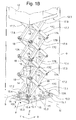
- Fig. 3 shows an example of a module pre-assembled in accordance with the before-mentioned method.
- the module comprises the platform 11, the guiding means 15, the scissor assembly 13 and the elevator car 12.
- the module is arranged on a platform 50 and ready for transport.
- Transportation can be done by means of a vehicle, helicopter or crane, for example. After the scissor elevator assembly and the elevator car or cabin arrived at the installation site, it has to be moved into the right position. This can be done by a crane, helicopter, or by means of a forklift or a transport trolly. A crane or helicopter is used if the scissor elevator assembly has to be lifted into an existing hoistway or into a pit.
- the installation on-site is easy and fast.
- the installation process comprises the following steps:
- the module may be lifted into an existing hoistway or pit, prior to positioning it.
- the drive mechanism 14 can be fixed to the mounting platform 11 on-site, so that it is capable of applying a force for unfolding the scissor assembly 13.
- the elevator car is mounted on the scissor elevator assembly. Depending on the size and weight of the elevator car, this can be done using a crane.
- the elevator car is then pivotally connected on the scissor elevator assembly.
- the wires are connected to a power supply or power outlet and, if available, additional sensors, touch buttons and switches are connected.
- the entire scissor-based elevator is designed with a special focus on simplifying the making and installment.
- the on-site installation costs are drastically used, according to the present invention.
- the logistics are simplified since the number of components to be shipped to the installation site are reduced.
Landscapes
- Engineering & Computer Science (AREA)
- Mechanical Engineering (AREA)
- Automation & Control Theory (AREA)
- Structural Engineering (AREA)
- Types And Forms Of Lifts (AREA)
Priority Applications (1)
| Application Number | Priority Date | Filing Date | Title |
|---|---|---|---|
| EP04405548A EP1512653A1 (de) | 2003-09-02 | 2004-09-02 | Methode zur Herstellung und Montage eines Aufzuges mit einem Scherenmachanismus |
Applications Claiming Priority (3)
| Application Number | Priority Date | Filing Date | Title |
|---|---|---|---|
| EP03405633 | 2003-09-02 | ||
| EP03405633 | 2003-09-02 | ||
| EP04405548A EP1512653A1 (de) | 2003-09-02 | 2004-09-02 | Methode zur Herstellung und Montage eines Aufzuges mit einem Scherenmachanismus |
Publications (1)
| Publication Number | Publication Date |
|---|---|
| EP1512653A1 true EP1512653A1 (de) | 2005-03-09 |
Family
ID=34137610
Family Applications (1)
| Application Number | Title | Priority Date | Filing Date |
|---|---|---|---|
| EP04405548A Withdrawn EP1512653A1 (de) | 2003-09-02 | 2004-09-02 | Methode zur Herstellung und Montage eines Aufzuges mit einem Scherenmachanismus |
Country Status (1)
| Country | Link |
|---|---|
| EP (1) | EP1512653A1 (de) |
Cited By (1)
| Publication number | Priority date | Publication date | Assignee | Title |
|---|---|---|---|---|
| CN113291729A (zh) * | 2021-05-28 | 2021-08-24 | 宁波中车时代电气设备有限公司 | 一种适用模块化站台门安装的安装设备 |
Citations (4)
| Publication number | Priority date | Publication date | Assignee | Title |
|---|---|---|---|---|
| GB1472063A (en) * | 1974-08-28 | 1977-04-27 | Hunter Ltd G | Scissor lift |
| GB2147927A (en) * | 1983-10-14 | 1985-05-22 | Geoffrey Cadman | Floor construction |
| US4741414A (en) * | 1987-03-13 | 1988-05-03 | Claassen Robert D | Lift apparatus for pallets |
| EP0962418A2 (de) * | 1998-06-08 | 1999-12-08 | Colin Roger Jeffery | Boden-Hebevorrichtung |
-
2004
- 2004-09-02 EP EP04405548A patent/EP1512653A1/de not_active Withdrawn
Patent Citations (4)
| Publication number | Priority date | Publication date | Assignee | Title |
|---|---|---|---|---|
| GB1472063A (en) * | 1974-08-28 | 1977-04-27 | Hunter Ltd G | Scissor lift |
| GB2147927A (en) * | 1983-10-14 | 1985-05-22 | Geoffrey Cadman | Floor construction |
| US4741414A (en) * | 1987-03-13 | 1988-05-03 | Claassen Robert D | Lift apparatus for pallets |
| EP0962418A2 (de) * | 1998-06-08 | 1999-12-08 | Colin Roger Jeffery | Boden-Hebevorrichtung |
Cited By (1)
| Publication number | Priority date | Publication date | Assignee | Title |
|---|---|---|---|---|
| CN113291729A (zh) * | 2021-05-28 | 2021-08-24 | 宁波中车时代电气设备有限公司 | 一种适用模块化站台门安装的安装设备 |
Similar Documents
| Publication | Publication Date | Title |
|---|---|---|
| KR101326793B1 (ko) | 고소작업대 | |
| CN101119920A (zh) | 可用一同时致动所有侧边的手柄折叠的电梯轿厢顶部扶栏 | |
| JPS6268964A (ja) | 伸縮自在な構造物 | |
| CN108571200B (zh) | 一种立体泊车装置及泊车方法 | |
| EP1509473B1 (de) | Sicherheitsumzäunung auf aufzugskabine | |
| CN112723267B (zh) | 一种工程施工用升降工作台 | |
| CN110937555A (zh) | 轨道检修车 | |
| US20050045427A1 (en) | Method for making and installing an elevator with a scissor lift mechanism | |
| CN115367670A (zh) | 一种地牛搬运器 | |
| EP1512653A1 (de) | Methode zur Herstellung und Montage eines Aufzuges mit einem Scherenmachanismus | |
| KR101557340B1 (ko) | 아치형 터널 구조물 시공용 리프트카 | |
| US20050045428A1 (en) | Elevator with a scissor lift assembly and a central drive mechanism | |
| US20090071751A1 (en) | Portable aerial platform | |
| EP1512654A1 (de) | Aufzug mit Hubscherensäulen und mit zentralem Antrieb | |
| EP2147891A1 (de) | Hubarbeitsbühne mit Scherenmechanismus | |
| US20050045426A1 (en) | Elevator with a scissor lift mechanism and a spring member serving as virtual counter weight | |
| CN118183562A (zh) | 一种液压升降作业平台防回落装置 | |
| KR19980036861A (ko) | 하단면주행식 교량하부면 작업대차의 내측작업대 | |
| JP4700661B2 (ja) | ボーディングブリッジ | |
| JPH08217392A (ja) | テーブルリフト装置 | |
| CN217025186U (zh) | 车载举升机 | |
| CN222374099U (zh) | 用于电梯安装的平台系统 | |
| JP3269755B2 (ja) | 高所作業車 | |
| WO2002066359A1 (en) | Elevator device | |
| EP1512655A1 (de) | Aufzug mit Hubscherensäulen und mit wie virtuellen Gegengewicht arbeitendem Federelement |
Legal Events
| Date | Code | Title | Description |
|---|---|---|---|
| PUAI | Public reference made under article 153(3) epc to a published international application that has entered the european phase |
Free format text: ORIGINAL CODE: 0009012 |
|
| AK | Designated contracting states |
Kind code of ref document: A1 Designated state(s): AT BE BG CH CY CZ DE DK EE ES FI FR GB GR HU IE IT LI LU MC NL PL PT RO SE SI SK TR |
|
| AX | Request for extension of the european patent |
Extension state: AL HR LT LV MK |
|
| 17P | Request for examination filed |
Effective date: 20050901 |
|
| AKX | Designation fees paid |
Designated state(s): AT CH DE FR GB LI |
|
| STAA | Information on the status of an ep patent application or granted ep patent |
Free format text: STATUS: THE APPLICATION IS DEEMED TO BE WITHDRAWN |
|
| 18D | Application deemed to be withdrawn |
Effective date: 20080401 |