EP1512645B1 - Fördersystem, insbesondere eine Flughafen-Gepackförderanlage - Google Patents
Fördersystem, insbesondere eine Flughafen-Gepackförderanlage Download PDFInfo
- Publication number
- EP1512645B1 EP1512645B1 EP04090305A EP04090305A EP1512645B1 EP 1512645 B1 EP1512645 B1 EP 1512645B1 EP 04090305 A EP04090305 A EP 04090305A EP 04090305 A EP04090305 A EP 04090305A EP 1512645 B1 EP1512645 B1 EP 1512645B1
- Authority
- EP
- European Patent Office
- Prior art keywords
- conveyor
- containers
- conveyor system
- guide
- container
- Prior art date
- Legal status (The legal status is an assumption and is not a legal conclusion. Google has not performed a legal analysis and makes no representation as to the accuracy of the status listed.)
- Expired - Lifetime
Links
- 239000002184 metal Substances 0.000 claims description 3
- 230000000284 resting effect Effects 0.000 claims description 2
- 239000000463 material Substances 0.000 description 4
- 239000004753 textile Substances 0.000 description 2
- 230000001133 acceleration Effects 0.000 description 1
- 230000006978 adaptation Effects 0.000 description 1
- 230000001737 promoting effect Effects 0.000 description 1
Images
Classifications
-
- B—PERFORMING OPERATIONS; TRANSPORTING
- B65—CONVEYING; PACKING; STORING; HANDLING THIN OR FILAMENTARY MATERIAL
- B65G—TRANSPORT OR STORAGE DEVICES, e.g. CONVEYORS FOR LOADING OR TIPPING, SHOP CONVEYOR SYSTEMS OR PNEUMATIC TUBE CONVEYORS
- B65G35/00—Mechanical conveyors not otherwise provided for
- B65G35/06—Mechanical conveyors not otherwise provided for comprising a load-carrier moving along a path, e.g. a closed path, and adapted to be engaged by any one of a series of traction elements spaced along the path
-
- B—PERFORMING OPERATIONS; TRANSPORTING
- B65—CONVEYING; PACKING; STORING; HANDLING THIN OR FILAMENTARY MATERIAL
- B65G—TRANSPORT OR STORAGE DEVICES, e.g. CONVEYORS FOR LOADING OR TIPPING, SHOP CONVEYOR SYSTEMS OR PNEUMATIC TUBE CONVEYORS
- B65G17/00—Conveyors having an endless traction element, e.g. a chain, transmitting movement to a continuous or substantially-continuous load-carrying surface or to a series of individual load-carriers; Endless-chain conveyors in which the chains form the load-carrying surface
- B65G17/002—Conveyors having an endless traction element, e.g. a chain, transmitting movement to a continuous or substantially-continuous load-carrying surface or to a series of individual load-carriers; Endless-chain conveyors in which the chains form the load-carrying surface comprising load carriers resting on the traction element
-
- B—PERFORMING OPERATIONS; TRANSPORTING
- B65—CONVEYING; PACKING; STORING; HANDLING THIN OR FILAMENTARY MATERIAL
- B65G—TRANSPORT OR STORAGE DEVICES, e.g. CONVEYORS FOR LOADING OR TIPPING, SHOP CONVEYOR SYSTEMS OR PNEUMATIC TUBE CONVEYORS
- B65G21/00—Supporting or protective framework or housings for endless load-carriers or traction elements of belt or chain conveyors
- B65G21/20—Means incorporated in, or attached to, framework or housings for guiding load-carriers, traction elements or loads supported on moving surfaces
- B65G21/2045—Mechanical means for guiding or retaining the load on the load-carrying surface
- B65G21/2054—Mechanical means for guiding or retaining the load on the load-carrying surface comprising elements movable in the direction of load-transport
Definitions
- the invention relates to a conveyor system, in particular an airport baggage conveyor system, according to the preamble of claim 1.
- the known conveyor system has the disadvantage that no controlled secure guidance of the container is ensured. This is particularly disadvantageous if the containers are to be X-rayed by means of an X-ray device provided on the conveyor track.
- a conveyor track for containers is known in which the containers are moved along the conveyor track.
- To move the container they are driven by conveyor belts, which are formed as endlessly circulating flat belts and guided over deflection wheels.
- a container side is in each case frictionally on a conveyed material; the other side of the container is supported by freely rotatable carrying rollers.
- To guide the container is a guide rail, which cooperates with a provided on the underside of the container pin-shaped guide member.
- the guide element is guided in the guide rail and prevented additionally a lifting of the container from the conveyor track.
- the guide takes place by means of two extending in the transport direction longitudinal sides of the guide rail, whereby the transverse movement of the container is prevented.
- DE 197 08 390 C2 discloses a track-bound material handling system with industrial trucks having rotatably mounted wheels which roll on a textile tread, which is located on a track material body and thus forms a tread for the wheels.
- band-shaped side guides limit the running surfaces.
- rollers roll inside with vertical axes of rotation, which are rotatably mounted on the underside of the trucks. Due to the thickness of the textile running coverings, the two running surfaces are located slightly above the base of the track base body, so that the guide rollers for lateral guidance of the trucks extend below the running surfaces.
- the object of the invention is to ensure a controlled safe "soft" leadership of the container in the conveyor system.
- the guide means is at least one groove-shaped recess formed in the container, in which engages the straight guide element and that the side guide elements are formed as formed on the groove side surfaces side guide rollers in the guide element, which protrude from the longitudinal sides.
- the side guide rollers roll on the two opposite groove side surfaces of the container, which causes a forced operation, which enforces a controlled safe guidance of the container.
- a further improvement results when the distance of the side guide roller pairs corresponds to the container length.
- the forces in the guidance of the containers are independent of their weight and the weight of the transported material, which means higher Acceleration and deceleration forces can be transmitted when the side guide rollers are driven.
- the support members are formed as side rails, which have both end pieces in which Gurt Equipmentsrollen are rotatably mounted, over which the conveyor belt runs, the conveying part on the top and the returning part on the underside of the side member.
- the length of a conveying element can be changed more easily if one of the side rails by means of an extendable or pushed into the side members intermediate piece can be extended, in which then the tail on or pushed.
- a simple belt change results when the belt guide rollers are crowned, so that the conveyor belt by hand up and is pushed off again.
- the groove-shaped recess is formed centrally in the bottom.
- the conveyor 1 has two side rails 2 arranged parallel to one another, which are connected to one another via cross members 3.
- front ends of the side rails 2 each have an end piece 4 is inserted or inserted and secured by screws 5 on the side rail 2.
- the end pieces 4 connected to the side rails 2 each form one end of the two side rails 2.
- the four ends of the side rails 2 carry rotatably mounted crowned Gurt Adjustsrollen 6, via each of which an endless conveyor belt 7 is guided.
- the containers 1a are during transport with their flat bottom on the two conveyor belts 7 and are supported by the side rails 2; they are effective as support elements 2a.
- the promotional part of Conveyor belts 7 runs on the top and the returning part on the underside of the side member 2.
- a guide element 8 Located centrally between the two side rails 2 is a guide element 8 as a guide means 8a, which runs parallel to the side rails 2 in the transport direction.
- the guide element 8 is made of lubricious plastic, but it may also be formed from a sheet metal.
- the guide element 8 has a rectangular cross-section, the ends tapering slightly in the transport direction.
- a pair of side guide rollers 10 are provided on the two longitudinal sides 9 of the guide element 8 as side guide elements (FIG. 1 shows only the two front side rollers 10 facing the observer, the rear side roller pair being concealed by the guide element 8 in FIG ).
- the side guide elements may also be lubricious plastic balls and the like.
- the side guide rollers 10 protrude just above the longitudinal side surfaces of the longitudinal sides 9 addition.
- the distance between the two side guide roller pairs 10, 10 corresponds approximately to the container length.
- the two rear belt guide rollers 6 are driven by a motor, of which only the drive pinion 11 is shown. About the drive pinion 11, a shaft 12 is driven, sit on the two rear Gurt Resultssrollen 6 rotatably.
- the side rollers 10 may be driven and so serve as a drive means.
- freely rotatable support rollers 12a are provided in the side rails, on which the conveyor belts 7 rest.
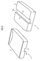
- Fig. 2 shows the container 1a left with a view of the top and right with a view of the bottom.
- longitudinal groove 13 In the underside extending in the direction of transport longitudinal groove 13 is formed with the two opposite groove side surfaces 14 as a recess 13a.
- the guide element 8 engages in the longitudinal groove 13, wherein the side guide rollers 10 roll on the two opposite groove side surfaces 14.
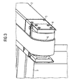
- Fig. 3 shows the end of the right side rail 2 with inserted end piece 4 in an enlarged view.
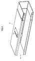
- an intermediate piece 15 is shown, which can be used to extend a side member 2.
- the end piece 4 is removed after loosening the screws 5 from the end of the side member 2 and the intermediate piece inserted instead of the end piece 4 and fastened by means of screws. Thereafter, the end piece 4 is inserted into the free opening 16 of the intermediate piece 15 and also fastened by means of screws 5 thereto.
- the conveyor belt 7 can each be conveniently off by hand and postponed again.
Landscapes
- Engineering & Computer Science (AREA)
- Mechanical Engineering (AREA)
- Framework For Endless Conveyors (AREA)
- Structure Of Belt Conveyors (AREA)
- Attitude Control For Articles On Conveyors (AREA)
- Intermediate Stations On Conveyors (AREA)
- Control Of Conveyors (AREA)
Description
- Die Erfindung betrifft ein Fördersystem, insbesondere eine Flughafen-Gepäckförderanlage, gemäß dem Oberbegriff des Anspruchs 1.
- Aus der US 2002/0063037 A1 ist bereits ein Fördersystem für den Transport von Behältern bekannt, die Stückgut in Form von Gepäckstücken entlang einer Förderstrecke transportieren. Die Förderstrecke weist eine Vielzahl von geraden Abschnitten auf, wobei die Behälter mit ihrer Unterseite beidseitig auf Gurtförderern aufliegen. Dabei erfahren die Behälter mittels Seitenwänden eine Ausrichtung und Führung.
- Das bekannte Fördersystem hat den Nachteil, dass keine kontrolliert sichere Führung der Behälter sichergestellt ist. Dies ist insbesondere dann von Nachteil, wenn die Behälter mittels einer an der Förderstrecke vorgesehenen Röntgeneinrichtung geröntgt werden sollen.
- Weiter ist aus der DE 197 07 321 A1 eine Förderbahn für Behälter bekannt, bei der die Behälter entlang der Förderbahn bewegt werden. Zum Bewegen der Behälter werden diese mit Fördergurten angetrieben, die als endlos umlaufende Flachgurte ausgebildet und über Umlenkräder geführt sind. Eine Behälterseite liegt dabei jeweils kraftschlüssig auf einem Fördergut auf; die andere Behälterseite ist über frei drehbare Tragrollen abgestützt. Zur Führung der Behälter dient eine Führungsschiene, die jeweils mit einem an der Unterseite der Behälter vorgesehenen stiftförmigen Führungselement zusammenwirkt. Das Führungselement ist in der Führungsschiene geführt und verhindert zusätzlich ein Abheben der Behälter von der Förderbahn. Die Führung erfolgt mittels zweier in Transportrichtung verlaufender Längsseiten der Führungsschiene, wobei auch die Querbewegung der Behälter verhindert wird.
- Außerdem ist aus der DE 699 03 284 T2 ein Fördersystem zum Transport von Gütern, beispielsweise Gepäckstücken an Flughäfen, bekannt, die in Behältern angeordnet sind, welche entlang einer Förderbahn durch Antriebsmittel in Form eines Gurtförderers bewegt werden. Die Gurtförderbahn weist gerade Führungsschienen für die Behälter auf. Die Führungsschienen greifen zur Führung jeweils in eine zwischen Rippen befindliche Behälternut ein.
- Ferner offenbart die DE 197 08 390 C2 ein gleisgebundenes Flurfördersystem mit Flurförderzeugen, die drehbar gelagerte Räder aufweisen, die auf einem textilen Laufbelag abrollen, der sich auf einem Gleisgutkörper befindet und so eine Lauffläche für die Räder bildet. Innenseitig begrenzen bandförmige Seitenführungen die Laufflächen. An diesen rollen innenseitig Führungsrollen mit vertikalen Drehachsen ab, die an der Unterseite der Flurförderzeuge drehgelagert sind. Durch die Dicke der textilen Laufbeläge befinden sich die beiden Laufflächen etwas oberhalb der Grundfläche des Gleisgrundkörpers, so dass sich die Führungsrollen zur seitlichen Führung der Flurförderzeuge bis unterhalb der Laufflächen erstrecken.
- Ein weiterer Fördersystem für Stückgut-Behälter ist aus der US 3753485 bekannt.
- Die Aufgabe der Erfindung ist es, eine kontrollierte sichere "weiche" Führung der Behälter im Fördersystem sicherzustellen.
- Die Lösung dieser Aufgabe ist durch die im Anspruch 1 angegebenen Merkmale gegeben. Durch die kennzeichnenden Merkmale der Unteransprüche ist das Fördersystem in vorteilhafter Weise weiter ausgestaltet.
- Die Lösung sieht vor, dass das Führungsmittel zumindest eine im Behälter eingeformte nutförmige Ausnehmung ist, in die das gerade Führungselement eingreift und dass die Seitenführungselemente als an den Nutseitenflächen abrollende Seitenführungsrollen ausgebildet im Führungselement angeordnet sind, die aus den Längsseiten herausragen. Die Seitenführungsrollen rollen an den beiden gegenüberliegenden Nutseitenflächen der Behälter ab, was eine Zwangsführung bewirkt, die eine kontrolliert sichere Führung der Behälter erzwingt.
- Aufgrund der kontrollierten sicheren Führung wird ermöglicht, dass im geraden Förderstreckenabschnitt einer Röntgeneinrichtung zum Röntgen der Stückgüter einschließlich Behälter angeordnet ist.
- Eine einfache konstruktive Ausführung sieht vor, dass die Behälter mit ihrer Unterseite unmittelbar auf Fördergurten aufliegend transportiert werden, die sich wiederum auf den Stützelementen abstützen.
- Wenn zumindest an einer Seitenfläche ein in Transportrichtung beabstandetes Paar Seitenführungsrollen angeordnet ist, lässt sich die Genauigkeit der Führung weiter verbessern.
- Eine nochmalige Verbesserung ergibt sich, wenn der Abstand der Seitenführungsrollenpaare der Behälterlänge entspricht.
- Die Kräfte bei der Führung der Behälter sind unabhängig von deren Gewicht und dem Gewicht des Fördergutes, wodurch höhere Beschleunigungs- und Verzögerungskräfte übertragen werden können, wenn die Seitenführungsrollen angetrieben sind.
- Eine sichere und gleichzeitig geschmeidigere Führung ergibt sich, wenn das Führungselement aus gleitfähigem Kunststoff oder aus Blech besteht.
- Eine Anpassung an unterschiedliche Fördersysteme wird erleichtert, wenn die Stützelemente als Seitenholme ausgebildet sind, die beidendig Endstücke aufweisen, in denen Gurtführungsrollen drehgelagert sind, über welche der Fördergurt läuft, der fördernde Teil auf der Oberseite und der rückführende Teil auf der Unterseite des Seitenholms.
- Konstruktiv einfach ist es, wenn die Endstücke in die Seitenholme eingeschoben oder aufgeschoben sind.
- Die Länge eines Förderelementes lässt sich leichter ändern, wenn eines die Seitenholme mittels eines in die Seitenholme ein- bzw. aufschiebbaren Zwischenstücks verlängerbar sind, in das dann das Endstück ein- bzw. aufschiebbar ist.
- Ein einfacher Gurtwechsel ergibt sich, wenn die Gurtführungsrollen ballig ausgebildet sind, so dass der Fördergurt von Hand auf- und wieder abschiebbar ist.
- Bei einem einfach ausgeführten Behälter ist die nutförmige Ausnehmung in die Unterseite mittig eingeformt.
- Die Erfindung wird nachfolgen anhand einer Zeichnung näher beschrieben. Es zeigen:
- Fig. 1
- einen Förderer eines geraden Förderstreckenabschnitts eines Fördersystems,
- Fig. 2
- einen für den Förderer gemäß Fig. 1 geeigneten Behälter,
- Fig. 3
- den Endbereich eines Seitenholms des Förderers gemäß Fig. 1 mit Endstück und
- Fig. 4
- ein Zwischenstück zur Verlängerung des Seitenholms gemäß Fig. 2.
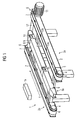
- Fig. 1 zeigt einen Förderer 1 eines geraden Förderstreckenabschnitts einer nicht gezeigten Flughafen-Gepäckförderanlage. Die Gepäckförderanlage dient zum Transport von Stückgut, das in Behältern 1a (s. Fig.2) in Transportrichtung T transportiert wird. Zum Röntgen der Stückgüter einschließlich Behälter 1a dient eine schematisch gezeigte Röntgeneinrichtung 1b.
- Der Förderer 1 weist zwei parallel zueinander angeordnete Seitenholme 2 auf, die über Querträger 3 miteinander verbunden sind. In die beiden bezogen auf Fig. 1 vorderen Enden der Seitenholme 2 ist jeweils ein Endstück 4 eingeschoben bzw. eingesteckt und mittels Schrauben 5 am Seitenholm 2 befestigt. Die mit den Seitenholmen 2 so verbundenen Endstücke 4 bilden jeweils ein Ende der beiden Seitenholme 2.
- Die vier Enden der Seitenholme 2 tragen drehgelagerte ballige Gurtführungsrollen 6, über welche jeweils ein endloser Fördergurt 7 geführt ist. Die Behälter 1a liegen beim Transport mit ihrer flachen Unterseite auf den beiden Fördergurten 7 auf und werden so von den Seitenholmen 2 abgestützt; sie sind dabei als Stützelemente 2a wirksam. Der fördernde Teil der Fördergurte 7 läuft dabei auf der Oberseite und der rückführende Teil auf der Unterseite des Seitenholms 2.
- Mittig zwischen den beiden Seitenholmen 2 befindet sich ein Führungselement 8 als Führungsmittel 8a, das parallel zu den Seitenholmen 2 in Transportrichtung verläuft. Das Führungselement 8 ist aus gleitfähigen Kunststoff hergestellt, es kann aber auch aus einem Blech geformt sein. Das Führungselement 8 hat einen rechteckigen Querschnitt, wobei die Enden sich in Transportrichtung gesehen leicht verjüngen.
- Wie Fig. 1 zeigt, ist an den beiden Längsseiten 9 des Führungselements 8 als Seitenführungselemente jeweils ein Paar Seitenführungsrollen 10 vorgesehen (Fig. 1 zeigt nur die beiden dem Betrachter zugewandten vorderen Seitenrollen 10; das hintere Seitenrollenpaar ist in Fig. 1 vom Führungselement 8 verdeckt). Bei den Seitenführungselementen kann es sich auch um gleitfähige Kunststoffkugeln und dergleichen handeln. Die Seitenführungsrollen 10 ragen knapp über die Längsseitenflächen der Längsseiten 9 hinaus. Der Abstand der beiden Seitenführungsrollenpaare 10, 10 entspricht etwa der Behälterlänge. Wie in Fig. 1 schematisch dargestellt, sind die beiden hinteren Gurtführungsrollen 6 von einem Motor angetrieben, von dem nur das Antriebsritzel 11 dargestellt ist. Über das Antriebsritzel 11 wird eine Welle 12 angetrieben, auf der die beiden hinteren Gurtführungsrollen 6 drehfest sitzen. Selbstverständlich können auch die Seitenrollen 10 angetrieben sein und so als Antriebsmittel dienen.
- Zur Verringerung des Reibungswiderstands der Fördergurte sind in den Seitenholmen 2 frei drehbare Stützrollen 12a vorgesehen, auf denen die Fördergurte 7 aufliegen.
- Fig. 2 zeigt den Behälter 1a links mit Blick auf die Oberseite und rechts mit Blick auf die Unterseite. In die Unterseite ist eine in Transportrichtung verlaufende Längsnut 13 mit den beiden gegenüberliegenden Nutseitenflächen 14 als Ausnehmung 13a ausgebildet. Beim Durchlaufen des Förderers 1 greift das Führungselement 8 in die Längsnut 13 ein, wobei die Seitenführungsrollen 10 an den beiden gegenüberliegenden Nutseitenflächen 14 abrollen.
- In Fig. 1 sitzen die beiden Rollenpaare 10, 10 in Transportrichtung T gesehen im hinteren Bereich des Führungselements 8. Auf diese Weise wird erreicht, dass ein einlaufender Behälter 1a zunächst vom Führungselement 8 grob ausgerichtet und geführt wird und dass dann mittels der Seitenführungsrollen 10 eine Feinausrichtung erfolgt.
- Dies prädestiniert diesen Förderer 1 zur Verwendung in Verbindung mit der Röntgeneinrichtung 1b.
- Fig. 3 zeigt das Ende des rechten Seitenholms 2 mit eingestecktem Endstück 4 in einer vergrößerten Darstellung.
- In Fig. 4 ist ein Zwischenstück 15 dargestellt, das zur Verlängerung eines Seitenholms 2 verwendet werden kann. Hierzu wird das Endstück 4 nach Lösen der Schrauben 5 vom Ende des Seitenholms 2 abgezogen und das Zwischenstück anstelle des Endstücks 4 eingeschoben und mittels Schrauben befestigt. Danach wird das Endstück 4 in die freie Öffnung 16 des Zwischenstücks 15 eingesteckt und ebenfalls mittels Schrauben 5 an diesem befestigt.
- Durch die ballige Form der Gurtführungsrollen 6 lässt sich der Fördergurt 7 jeweils bequem von Hand ab- und auch wieder aufschieben.
Claims (7)
- Fördersystem, insbesondere eine Flughafen-Gepäckförderanlage, mit zum Transport von Stückgut dienenden Behältern (1a), die entlang einer zumindest abschnittsweise geraden Förderstrecke mit ihrer Unterseite von Stützelementen (2a) abgestützt transportiert werden, wobei an der Förderstrecke Führungsmittel (8a) zur Ausrichtung und Führung der Behälter (1a) vorgesehen sind, deren Behälterunterseite mit jeweils zumindest einem in Transportrichtung verlaufenden geraden Führungselement (8) in Form einer im Behälter (1a) eingeformten nutförmigen Ausnehmung (13a) versehen ist, in welche die an der Förderstrecke vorgesehenen Führungsmittel (8a) eingreifen, wobei die Führungsmittel (8a) an ihren beiden Längsseiten (9) mit je einer Reihe Seitenführungsrollen (10) versehen sind, welche, aus den Längsseiten (9) herausragend, an den Nutseitenflächen (14) der nutförmigen Ausnehmung (13a) abrollen.
- Fördersystem nach Anspruch 1,
dadurch gekennzeichnet,
dass die Behälter (1a) mit ihrer Unterseite unmittelbar auf Fördergurten (7) aufliegend transportiert werden, die sich wiederum auf den Stützelementen (2a) abstützen. - Fördersystem nach Anspruch 1 oder 2,
dadurch gekennzeichnet,
dass zumindest an einer Längsseite (9) ein in Transportrichtung beabstandetes Paar Seitenführungsrollen (10) angeordnet ist. - Fördersystem nach Anspruch 3,
dadurch gekennzeichnet,
dass der Abstand der Seitenführungsrollenpaare (10, 10) der Behälterlänge entspricht. - Fördersystem nach einem der Ansprüche 1 - 4,
dadurch gekennzeichnet,
dass die Seitenführungsrollen (10) angetrieben sind. - Fördersystem nach einem der Ansprüche 1 - 5,
dadurch gekennzeichnet,
dass das Führungselement (8) aus gleitfähigem Kunststoff oder aus Blech besteht. - Fördersystem nach einem der Ansprüche 1 - 11,
dadurch gekennzeichnet,
dass die nutförmige Ausnehmung (13a) in die Unterseiten der Behälter (1a) mittig eingeformt ist.
Applications Claiming Priority (2)
| Application Number | Priority Date | Filing Date | Title |
|---|---|---|---|
| DE10340867A DE10340867B4 (de) | 2003-09-04 | 2003-09-04 | Fördersystem, insbesondere eine Flughafen-Gepäckförderanlage |
| DE10340867 | 2003-09-04 |
Publications (3)
| Publication Number | Publication Date |
|---|---|
| EP1512645A2 EP1512645A2 (de) | 2005-03-09 |
| EP1512645A3 EP1512645A3 (de) | 2005-04-27 |
| EP1512645B1 true EP1512645B1 (de) | 2007-06-06 |
Family
ID=34129652
Family Applications (1)
| Application Number | Title | Priority Date | Filing Date |
|---|---|---|---|
| EP04090305A Expired - Lifetime EP1512645B1 (de) | 2003-09-04 | 2004-07-30 | Fördersystem, insbesondere eine Flughafen-Gepackförderanlage |
Country Status (4)
| Country | Link |
|---|---|
| US (1) | US7131523B2 (de) |
| EP (1) | EP1512645B1 (de) |
| AT (1) | ATE364023T1 (de) |
| DE (2) | DE10340867B4 (de) |
Families Citing this family (8)
| Publication number | Priority date | Publication date | Assignee | Title |
|---|---|---|---|---|
| DE102006062530B4 (de) * | 2006-12-29 | 2016-06-23 | Siegmund Kumeth | Transportsystem für Werkstücke |
| DE102009023287A1 (de) * | 2009-05-29 | 2010-12-02 | Krones Ag | Bandfördereinrichtung |
| CN102295145A (zh) * | 2011-06-02 | 2011-12-28 | 济南奥图自动化工程有限公司 | 直线伺服输送系统 |
| DK2838806T3 (en) * | 2012-05-29 | 2018-11-26 | Siemens Ag | Container for transporting luggage in a sorting and sorting plant |
| CN103303635B (zh) * | 2013-06-28 | 2014-03-12 | 格兰克克拉克(苏州)挤压技术设备有限公司 | 一种带式输送系统 |
| CN106865107A (zh) * | 2017-03-17 | 2017-06-20 | 上海科星五金股份有限公司 | 一种安检周转箱自动回输设备 |
| GB201805669D0 (en) * | 2018-04-05 | 2018-05-23 | Kromek Ltd | Conveyor System |
| US20230373445A1 (en) * | 2022-05-23 | 2023-11-23 | International Drying Corporation | Car Wash Conveyor Belt Lifting System |
Family Cites Families (11)
| Publication number | Priority date | Publication date | Assignee | Title |
|---|---|---|---|---|
| GB1317118A (en) * | 1971-10-13 | 1973-05-16 | Fromme Foerderanlagen Gmbh | Pallet conveyors |
| US4014428A (en) * | 1973-05-04 | 1977-03-29 | Ossbahr C | Modular article conveyor |
| US5388684A (en) * | 1994-02-22 | 1995-02-14 | Peck Automated Systems, Inc. | Pallet conveyor |
| DE19707321A1 (de) * | 1997-02-12 | 1998-08-13 | Mannesmann Ag | Förderbahn für Stückgut, insbesondere für Gepäck-Behälter |
| DE19708390C2 (de) * | 1997-03-01 | 2003-04-17 | Swisslog Deutschland Gmbh | Gleisgebundenes Flurfördersystem |
| AU1751199A (en) * | 1997-12-12 | 1999-07-05 | Crisplant A/S | A conveyer system and a method for operating same |
| IT243803Y1 (it) * | 1998-02-25 | 2002-03-06 | Fata Automation | Dispositivo di trasporto lungo linee di assemblaggio e simili |
| NL1009222C2 (nl) * | 1998-05-20 | 1999-11-24 | Vanderlande Ind Nederland | Werkwijze en installatie voor het transporteren van goederen alsmede combinatie van een bak en van een door wielen ondersteund frame voor het transporteren van goederen. |
| EP1452464A1 (de) * | 2003-02-27 | 2004-09-01 | Siemens Aktiengesellschaft | Kurve eines Fördersystems für Behälter insbesondere eine Flughafen-Gepäckförderanlage |
| DE10321915B3 (de) * | 2003-05-15 | 2005-06-09 | Siemens Ag | Steigung für ein Behälter-Fördersystem, insbesondere eine Flughafen-Gepäckförderanlage |
| DE10340868B4 (de) * | 2003-09-04 | 2005-09-29 | Siemens Ag | Fördersystem, insbesondere eine Flughafengepäckförderanlage, für zum Transport von Stückgut dienenden Behältern |
-
2003
- 2003-09-04 DE DE10340867A patent/DE10340867B4/de not_active Expired - Fee Related
-
2004
- 2004-07-30 AT AT04090305T patent/ATE364023T1/de not_active IP Right Cessation
- 2004-07-30 DE DE502004004015T patent/DE502004004015D1/de not_active Expired - Fee Related
- 2004-07-30 EP EP04090305A patent/EP1512645B1/de not_active Expired - Lifetime
- 2004-09-07 US US10/935,715 patent/US7131523B2/en not_active Expired - Fee Related
Also Published As
| Publication number | Publication date |
|---|---|
| DE502004004015D1 (de) | 2007-07-19 |
| DE10340867B4 (de) | 2005-09-29 |
| DE10340867A1 (de) | 2005-04-07 |
| US7131523B2 (en) | 2006-11-07 |
| ATE364023T1 (de) | 2007-06-15 |
| EP1512645A3 (de) | 2005-04-27 |
| EP1512645A2 (de) | 2005-03-09 |
| US20050056528A1 (en) | 2005-03-17 |
Similar Documents
| Publication | Publication Date | Title |
|---|---|---|
| AT500109B1 (de) | Übergabevorrichtung zum seitlichen ausschleusen von fördergut sowie eine fördereinrichtung | |
| EP1041019B1 (de) | Stückgut-(Stetig-)Fördereinrichtung | |
| DE2314794A1 (de) | Vorrichtung fuer den vertikalen transport von koerpern | |
| DE10340868B4 (de) | Fördersystem, insbesondere eine Flughafengepäckförderanlage, für zum Transport von Stückgut dienenden Behältern | |
| EP1464595A2 (de) | Fördersystem, insbesondere eine Flughafen-Gepäckförderanlage, für Behälter | |
| EP0541850B1 (de) | Kurvengängiges Plattenband | |
| EP0802129A2 (de) | Förderbahn für Stückgut, insbesondere für Gepäck-Behälter | |
| EP1512645B1 (de) | Fördersystem, insbesondere eine Flughafen-Gepackförderanlage | |
| DE603291C (de) | Auf Schienen fahrbarer universalbeweglicher Plattenbandfoerderer | |
| DE2855982A1 (de) | Stueckgut-transportvorrichtung | |
| DE102015012001A1 (de) | Fördervorrichtung zum Fördern von Transportstrukturen | |
| EP0396925B1 (de) | C- Förderer | |
| DE3432042A1 (de) | Staufoerder- und zugkette | |
| EP1477433A1 (de) | Fördersystem für Behälter, insbesondere eine Flughafen-Gepäckförderanlage, sowie eine vertikal konvex gekrümmte Steigung für ein Fördersystem | |
| AT401506B (de) | Sortiereinrichtung mit einem endlosen gliederförderer | |
| DE9312243U1 (de) | Fördereinrichtung | |
| EP1452465A1 (de) | Fördersystem für Behälter, insbesondere eine Flughafen-Gepäckförderanlage | |
| DE1249765B (de) | ||
| EP2551217A1 (de) | Fördervorrichtung für Gegenstände | |
| EP0899221A1 (de) | Gliederförderer zum Transport von Stückgut, insbesondere Gepäckstücken | |
| DE10044612A1 (de) | Kippstation für Stückgutförderer | |
| EP1475324B1 (de) | Fördersystem für Behälter, insbesondere eine Flughafen-Gepäckförderanlage, und eine vertikale Weiche für ein Fördersystem | |
| DE212010000147U1 (de) | Fördersystem | |
| DE10315505B4 (de) | Fördersystem mit Kurve für Behälter, insbesondere eine Flughafen-Gepäckförderanlage | |
| DE3914505C2 (de) |
Legal Events
| Date | Code | Title | Description |
|---|---|---|---|
| PUAI | Public reference made under article 153(3) epc to a published international application that has entered the european phase |
Free format text: ORIGINAL CODE: 0009012 |
|
| AK | Designated contracting states |
Kind code of ref document: A2 Designated state(s): AT BE BG CH CY CZ DE DK EE ES FI FR GB GR HU IE IT LI LU MC NL PL PT RO SE SI SK TR |
|
| AX | Request for extension of the european patent |
Extension state: AL HR LT LV MK |
|
| PUAL | Search report despatched |
Free format text: ORIGINAL CODE: 0009013 |
|
| AK | Designated contracting states |
Kind code of ref document: A3 Designated state(s): AT BE BG CH CY CZ DE DK EE ES FI FR GB GR HU IE IT LI LU MC NL PL PT RO SE SI SK TR |
|
| AX | Request for extension of the european patent |
Extension state: AL HR LT LV MK |
|
| 17P | Request for examination filed |
Effective date: 20051010 |
|
| AKX | Designation fees paid |
Designated state(s): AT BE BG CH CY CZ DE DK EE ES FI FR GB GR HU IE IT LI LU MC NL PL PT RO SE SI SK TR |
|
| GRAP | Despatch of communication of intention to grant a patent |
Free format text: ORIGINAL CODE: EPIDOSNIGR1 |
|
| GRAS | Grant fee paid |
Free format text: ORIGINAL CODE: EPIDOSNIGR3 |
|
| GRAA | (expected) grant |
Free format text: ORIGINAL CODE: 0009210 |
|
| AK | Designated contracting states |
Kind code of ref document: B1 Designated state(s): AT BE BG CH CY CZ DE DK EE ES FI FR GB GR HU IE IT LI LU MC NL PL PT RO SE SI SK TR |
|
| PG25 | Lapsed in a contracting state [announced via postgrant information from national office to epo] |
Ref country code: FI Free format text: LAPSE BECAUSE OF FAILURE TO SUBMIT A TRANSLATION OF THE DESCRIPTION OR TO PAY THE FEE WITHIN THE PRESCRIBED TIME-LIMIT Effective date: 20070606 |
|
| REG | Reference to a national code |
Ref country code: GB Ref legal event code: FG4D Free format text: NOT ENGLISH |
|
| REG | Reference to a national code |
Ref country code: CH Ref legal event code: EP |
|
| REG | Reference to a national code |
Ref country code: IE Ref legal event code: FG4D Free format text: LANGUAGE OF EP DOCUMENT: GERMAN |
|
| REF | Corresponds to: |
Ref document number: 502004004015 Country of ref document: DE Date of ref document: 20070719 Kind code of ref document: P |
|
| PG25 | Lapsed in a contracting state [announced via postgrant information from national office to epo] |
Ref country code: SE Free format text: LAPSE BECAUSE OF FAILURE TO SUBMIT A TRANSLATION OF THE DESCRIPTION OR TO PAY THE FEE WITHIN THE PRESCRIBED TIME-LIMIT Effective date: 20070906 |
|
| PG25 | Lapsed in a contracting state [announced via postgrant information from national office to epo] |
Ref country code: ES Free format text: LAPSE BECAUSE OF FAILURE TO SUBMIT A TRANSLATION OF THE DESCRIPTION OR TO PAY THE FEE WITHIN THE PRESCRIBED TIME-LIMIT Effective date: 20070917 |
|
| PG25 | Lapsed in a contracting state [announced via postgrant information from national office to epo] |
Ref country code: PL Free format text: LAPSE BECAUSE OF FAILURE TO SUBMIT A TRANSLATION OF THE DESCRIPTION OR TO PAY THE FEE WITHIN THE PRESCRIBED TIME-LIMIT Effective date: 20070606 |
|
| NLV1 | Nl: lapsed or annulled due to failure to fulfill the requirements of art. 29p and 29m of the patents act | ||
| GBV | Gb: ep patent (uk) treated as always having been void in accordance with gb section 77(7)/1977 [no translation filed] |
Effective date: 20070606 |
|
| REG | Reference to a national code |
Ref country code: IE Ref legal event code: FD4D |
|
| BERE | Be: lapsed |
Owner name: SIEMENS A.G. Effective date: 20070731 |
|
| PG25 | Lapsed in a contracting state [announced via postgrant information from national office to epo] |
Ref country code: SI Free format text: LAPSE BECAUSE OF FAILURE TO SUBMIT A TRANSLATION OF THE DESCRIPTION OR TO PAY THE FEE WITHIN THE PRESCRIBED TIME-LIMIT Effective date: 20070606 Ref country code: NL Free format text: LAPSE BECAUSE OF FAILURE TO SUBMIT A TRANSLATION OF THE DESCRIPTION OR TO PAY THE FEE WITHIN THE PRESCRIBED TIME-LIMIT Effective date: 20070606 Ref country code: CZ Free format text: LAPSE BECAUSE OF FAILURE TO SUBMIT A TRANSLATION OF THE DESCRIPTION OR TO PAY THE FEE WITHIN THE PRESCRIBED TIME-LIMIT Effective date: 20070606 Ref country code: IE Free format text: LAPSE BECAUSE OF FAILURE TO SUBMIT A TRANSLATION OF THE DESCRIPTION OR TO PAY THE FEE WITHIN THE PRESCRIBED TIME-LIMIT Effective date: 20070606 Ref country code: PT Free format text: LAPSE BECAUSE OF FAILURE TO SUBMIT A TRANSLATION OF THE DESCRIPTION OR TO PAY THE FEE WITHIN THE PRESCRIBED TIME-LIMIT Effective date: 20071106 Ref country code: BG Free format text: LAPSE BECAUSE OF FAILURE TO SUBMIT A TRANSLATION OF THE DESCRIPTION OR TO PAY THE FEE WITHIN THE PRESCRIBED TIME-LIMIT Effective date: 20070906 |
|
| EN | Fr: translation not filed | ||
| PG25 | Lapsed in a contracting state [announced via postgrant information from national office to epo] |
Ref country code: SK Free format text: LAPSE BECAUSE OF FAILURE TO SUBMIT A TRANSLATION OF THE DESCRIPTION OR TO PAY THE FEE WITHIN THE PRESCRIBED TIME-LIMIT Effective date: 20070606 |
|
| PLBE | No opposition filed within time limit |
Free format text: ORIGINAL CODE: 0009261 |
|
| STAA | Information on the status of an ep patent application or granted ep patent |
Free format text: STATUS: NO OPPOSITION FILED WITHIN TIME LIMIT |
|
| PG25 | Lapsed in a contracting state [announced via postgrant information from national office to epo] |
Ref country code: MC Free format text: LAPSE BECAUSE OF NON-PAYMENT OF DUE FEES Effective date: 20070731 Ref country code: DE Free format text: LAPSE BECAUSE OF NON-PAYMENT OF DUE FEES Effective date: 20080201 Ref country code: DK Free format text: LAPSE BECAUSE OF FAILURE TO SUBMIT A TRANSLATION OF THE DESCRIPTION OR TO PAY THE FEE WITHIN THE PRESCRIBED TIME-LIMIT Effective date: 20070606 Ref country code: IT Free format text: LAPSE BECAUSE OF FAILURE TO SUBMIT A TRANSLATION OF THE DESCRIPTION OR TO PAY THE FEE WITHIN THE PRESCRIBED TIME-LIMIT Effective date: 20070606 Ref country code: GB Free format text: LAPSE BECAUSE OF FAILURE TO SUBMIT A TRANSLATION OF THE DESCRIPTION OR TO PAY THE FEE WITHIN THE PRESCRIBED TIME-LIMIT Effective date: 20070606 Ref country code: GR Free format text: LAPSE BECAUSE OF FAILURE TO SUBMIT A TRANSLATION OF THE DESCRIPTION OR TO PAY THE FEE WITHIN THE PRESCRIBED TIME-LIMIT Effective date: 20070907 |
|
| 26N | No opposition filed |
Effective date: 20080307 |
|
| PG25 | Lapsed in a contracting state [announced via postgrant information from national office to epo] |
Ref country code: RO Free format text: LAPSE BECAUSE OF FAILURE TO SUBMIT A TRANSLATION OF THE DESCRIPTION OR TO PAY THE FEE WITHIN THE PRESCRIBED TIME-LIMIT Effective date: 20070606 |
|
| PG25 | Lapsed in a contracting state [announced via postgrant information from national office to epo] |
Ref country code: FR Free format text: LAPSE BECAUSE OF FAILURE TO SUBMIT A TRANSLATION OF THE DESCRIPTION OR TO PAY THE FEE WITHIN THE PRESCRIBED TIME-LIMIT Effective date: 20080201 |
|
| PG25 | Lapsed in a contracting state [announced via postgrant information from national office to epo] |
Ref country code: BE Free format text: LAPSE BECAUSE OF NON-PAYMENT OF DUE FEES Effective date: 20070731 |
|
| PG25 | Lapsed in a contracting state [announced via postgrant information from national office to epo] |
Ref country code: AT Free format text: LAPSE BECAUSE OF NON-PAYMENT OF DUE FEES Effective date: 20070730 |
|
| PG25 | Lapsed in a contracting state [announced via postgrant information from national office to epo] |
Ref country code: EE Free format text: LAPSE BECAUSE OF FAILURE TO SUBMIT A TRANSLATION OF THE DESCRIPTION OR TO PAY THE FEE WITHIN THE PRESCRIBED TIME-LIMIT Effective date: 20070606 |
|
| REG | Reference to a national code |
Ref country code: CH Ref legal event code: PL |
|
| PG25 | Lapsed in a contracting state [announced via postgrant information from national office to epo] |
Ref country code: LI Free format text: LAPSE BECAUSE OF NON-PAYMENT OF DUE FEES Effective date: 20080731 Ref country code: CH Free format text: LAPSE BECAUSE OF NON-PAYMENT OF DUE FEES Effective date: 20080731 |
|
| PG25 | Lapsed in a contracting state [announced via postgrant information from national office to epo] |
Ref country code: CY Free format text: LAPSE BECAUSE OF FAILURE TO SUBMIT A TRANSLATION OF THE DESCRIPTION OR TO PAY THE FEE WITHIN THE PRESCRIBED TIME-LIMIT Effective date: 20070606 |
|
| PG25 | Lapsed in a contracting state [announced via postgrant information from national office to epo] |
Ref country code: LU Free format text: LAPSE BECAUSE OF NON-PAYMENT OF DUE FEES Effective date: 20070730 |
|
| PG25 | Lapsed in a contracting state [announced via postgrant information from national office to epo] |
Ref country code: TR Free format text: LAPSE BECAUSE OF FAILURE TO SUBMIT A TRANSLATION OF THE DESCRIPTION OR TO PAY THE FEE WITHIN THE PRESCRIBED TIME-LIMIT Effective date: 20070606 Ref country code: HU Free format text: LAPSE BECAUSE OF FAILURE TO SUBMIT A TRANSLATION OF THE DESCRIPTION OR TO PAY THE FEE WITHIN THE PRESCRIBED TIME-LIMIT Effective date: 20071207 |