EP1512449B1 - Verfahren zur Regelung von fortschreitender Gefrierkonzentrierung - Google Patents
Verfahren zur Regelung von fortschreitender Gefrierkonzentrierung Download PDFInfo
- Publication number
- EP1512449B1 EP1512449B1 EP04255362A EP04255362A EP1512449B1 EP 1512449 B1 EP1512449 B1 EP 1512449B1 EP 04255362 A EP04255362 A EP 04255362A EP 04255362 A EP04255362 A EP 04255362A EP 1512449 B1 EP1512449 B1 EP 1512449B1
- Authority
- EP
- European Patent Office
- Prior art keywords
- target
- liquid
- flow route
- cooling
- volume
- Prior art date
- Legal status (The legal status is an assumption and is not a legal conclusion. Google has not performed a legal analysis and makes no representation as to the accuracy of the status listed.)
- Expired - Lifetime
Links
- 238000000034 method Methods 0.000 title claims abstract description 42
- 230000000750 progressive effect Effects 0.000 title claims abstract description 13
- 239000007788 liquid Substances 0.000 claims abstract description 181
- 239000002826 coolant Substances 0.000 claims abstract description 84
- 239000013078 crystal Substances 0.000 claims abstract description 41
- 238000005192 partition Methods 0.000 description 5
- 238000010586 diagram Methods 0.000 description 4
- DNIAPMSPPWPWGF-UHFFFAOYSA-N Propylene glycol Chemical compound CC(O)CO DNIAPMSPPWPWGF-UHFFFAOYSA-N 0.000 description 3
- 235000013305 food Nutrition 0.000 description 3
- 239000012141 concentrate Substances 0.000 description 2
- 239000007864 aqueous solution Substances 0.000 description 1
- 238000002425 crystallisation Methods 0.000 description 1
- 239000003814 drug Substances 0.000 description 1
- 238000005516 engineering process Methods 0.000 description 1
- 239000000203 mixture Substances 0.000 description 1
- 230000002250 progressing effect Effects 0.000 description 1
- 239000000126 substance Substances 0.000 description 1
- 239000000725 suspension Substances 0.000 description 1
- 235000015193 tomato juice Nutrition 0.000 description 1
Images

Classifications
-
- B—PERFORMING OPERATIONS; TRANSPORTING
- B01—PHYSICAL OR CHEMICAL PROCESSES OR APPARATUS IN GENERAL
- B01D—SEPARATION
- B01D9/00—Crystallisation
- B01D9/0004—Crystallisation cooling by heat exchange
- B01D9/0013—Crystallisation cooling by heat exchange by indirect heat exchange
-
- B—PERFORMING OPERATIONS; TRANSPORTING
- B01—PHYSICAL OR CHEMICAL PROCESSES OR APPARATUS IN GENERAL
- B01D—SEPARATION
- B01D9/00—Crystallisation
- B01D9/0063—Control or regulation
-
- B—PERFORMING OPERATIONS; TRANSPORTING
- B01—PHYSICAL OR CHEMICAL PROCESSES OR APPARATUS IN GENERAL
- B01D—SEPARATION
- B01D9/00—Crystallisation
- B01D9/02—Crystallisation from solutions
- B01D9/04—Crystallisation from solutions concentrating solutions by removing frozen solvent therefrom
Definitions
- This invention relates to a method of controlling progressive freeze-concentration.
- the so-called freeze-concentration method is coming to be noted for concentrating target liquids of foods and medicaments for obtaining concentrates of a superior quality.
- both the suspension crystallization method and the progressive freeze-concentration method are known as examples of the freeze-concentration method
- the present invention relates to the progressive freeze-concentration method and in particular to a control method for the progressive freeze-concentration of a target liquid while a target liquid and a cooling medium are being circulated.
- the flow rate of the target liquid and the growth speed of the ice front at the ice-liquid interface during the freeze-concentration are two important factors that significantly influence the effective freeze-concentration of the target liquid. If the flow rate of the target liquid at the ice-liquid interface is too slow, the content ratio of solute to the ice crystals becomes accordingly too high. If it is too fast, on the other hand, the load on the freeze-concentration apparatus becomes accordingly large. If the growth speed of the ice crystal is too fast, the content ratio of solute to the ice crystal becomes accordingly too high. If it is too slow, on the other hand, the time of freeze-concentration becomes accordingly too long.
- a method of this invention for controlling progressive freeze-concentration may be characterized as comprising the steps of circulating a cooling medium through a cooling-medium flow route of a freeze-concentration apparatus while circulating a target liquid for freeze-concentration through a target-liquid flow route of this freeze-concentration apparatus, thereby gradually forming ice crystals on wall surfaces of the target-liquid flow route in freeze-concentration of the target liquid, connecting to this target-liquid flow route a volume expansion detecting means for detecting volume expansion of the target liquid, obtaining thickness of the ice crystals in the target-liquid flow route from volume expansion detected by the volume expansion detecting means, and controlling flow rate of the target liquid and growth speed of the ice front in the target-liquid flow route to become respectively a set flow rate value and a set growth speed value by carrying out Operation A and Operation B to be described below, based on the obtained thickness.
- Operation A is an operation comprising the steps of calculating inner diameter of the ice crystals in the target-liquid flow route from the obtained thickness, calculating a required flow volume of the target liquid in the target-liquid flow route from the calculated inner diameter and the set flow rate, and adjusting circulation volume of the target liquid such that measured flow volume of the target liquid inside the target-liquid flow route becomes equal to the required flow volume
- Operation B is an operation comprising the steps of calculating actual growth speed of the ice front in the target-liquid flow route from the obtained thickness and adjusting temperature and/or circulation volume of the cooling medium such that the calculated actual growth speed becomes equal to the set growth speed value.
- the method of this invention is of the prior art type of circulating a cooling medium through a cooling-medium flow route of a freeze-concentration apparatus while circulating a target liquid for freeze-concentration through a target-liquid flow route of this freeze-concentration apparatus, thereby gradually forming ice crystals on wall surfaces of the target-liquid flow route but is distinguishable in that the flow rate of the target liquid and the growth speed of the ice front in the target-liquid flow route are adjusted so as to assume optimum values set therefor.
- the freeze-concentration apparatus to be used may comprise one or more cylindrical double tubes. If a plurality of such double tubes are provided, they may be arranged in different ways with the tubes connected in series or in parallel but arrangements with double tubes each having a target-liquid flow route formed inside and a cooling-medium flow route formed outside are preferred. Those having two or more of such cylindrical double tubes and having the target-liquid flow routes so as to together form a single circulating flow route are even more preferable.
- a volume expansion detecting means for the target liquid is connected to the target-liquid flow route of the freeze-concentration apparatus and the thickness of the ice crystals in the target-liquid flow route is obtained from the volume expansion of the target liquid detected by this detecting means.
- the ice crystals grow on the wall surfaces of the target-liquid flow route and the total amount of the target liquid appears to increase by its volume expansion. Since the shape and the size of the target-liquid flow route, that is, its diameter and length, are known quantities, the thickness of the ice crystals in the target-liquid flow route can be easily calculated from the detected volume expansion of the target liquid.
- detecting volume expansion may be used for the purpose of this invention, but the type adapted to receive the overflowing portion of the target liquid from the target-liquid flow route in a receptacle and to measure its quantity by pressure, weight or its liquid surface level is preferred. Also preferable is the type adapted to detect an integrated flow volume of the target liquid spilled out of the target-liquid flow route.
- Operation A and Operation B are thereafter carried out on the basis of the thickness of the ice crystals in the target-liquid flow route thus obtained such that the flow rate of the target liquid and growth speed of the ice front in the target-liquid flow route will become respectively equal to a set flow rate value and a set growth speed value.
- the inner diameter of the ice crystals in the target-liquid flow route is calculated from the thickness of the ice crystals
- a required flow volume of the target liquid in the target-liquid flow route is calculated from the inner diameter thus calculated and the set flow rate
- the circulation volume of the target liquid is adjusted such that the measured flow volume of the target liquid inside the target-liquid flow route becomes equal to the required flow volume.
- the actual growth speed of the ice front in the target-liquid flow route is calculated from the thickness of the ice crystals and the temperature and/or the circulation volume of the cooling medium is adjusted such that the calculated actual growth speed becomes equal to the set growth speed value.
- Any known method may be used for adjusting the circulation of the target liquid in Operation A but it is preferable to do so by controlling the rotary motion of a target-liquid circulating pump by a frequency control.
- Any known method may be used also for adjusting the temperature of the cooling medium in Operation B but it is preferable to do so by controlling a cooler which is adapted to cool the cooling medium and it is even more preferable to do so by controlling flow volume of a portion of the cooling medium that is supplied from a cooling-medium tank connected to a cooler to an inlet to the cooling-medium flow route and of another portion of the cooling medium that is discharged from an outlet from the cooling-medium flow route and returned to the inlet to the cooling-medium flow route without passing through the cooling-medium tank.
- Any known method may further be used for adjusting the circulation of the cooling medium in Operation B but it is preferable to do so by controlling rotary motion of a cooling-medium circulating pump by a frequency control.
- the present invention makes it possible to control two of the most important factors in the progressive freeze-concentration by circulating both a target liquid and a cooling medium, that is, to control the flow rate of the target liquid and the growth speed of the ice front at their ice-liquid interface during the freeze-concentration process according to optimum values set therefor.
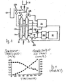
- Fig. 1 is a system diagram showing the method of control according to this invention.
- Two cylindrical double tubes 11 and 12 are provided, each having a target-liquid flow route 11a or 12a formed inside and a cooling-medium flow route 11b or 12b formed outside.
- the two target-liquid flow routes 11a and 12a are connected so as to together form a single circulating flow route 11c.
- a supply container 21 for the target liquid is disposed above the cylindrical double tubes 11 and 12 and is connected to the circulating flow route 11c.
- the two cooling-medium flow routes 11b and 12b are connected together at its upper and lower parts.
- An inlet and an outlet for the cooling medium are provided respectively at a lower part and an upper part of the cooling-medium flow route 12b. The inlet and the outlet are both connected to a cooler 31.
- a pump 41 for circulating the target liquid is provided to the circulating flow route 11c above the target-liquid flow route 11a.
- a flow-out tube 51 branches out of a connecting tube which connects a point on the circulating flow route 11c further above the pump 41 and the supply container 21. The tip part of the flow-out tube 51 is received in a receptacle 51a.
- Another pump 42 for circulating the cooling medium is provided between the inlet of the cooling medium into the cooling-medium flow route 12b and the cooler 31.
- a pressure sensor 61a is provided at the bottom of the receptacle 51a, a flowmeter 61b is inserted into the circulating flow route 11c above the target-liquid flow route 12a and a temperature sensor 61c is provided between the pump 42 and the inlet for the cooling medium into the cooling-medium flow route 12b.
- the pressure sensor 61 a, the flowmeter 61b and the temperature sensor 61c are all connected to a calculation controller 71 which is also connected to the cooler 31 and the pump 41.
- the target liquid is filled from the supply container 21 into the circulating flow route 11c including the target-liquid flow routes 11a and 12a.
- the pump 41 is activated to circulate the target liquid in the counter-clockwise direction (with reference to Fig. 1 ) through the target-liquid flow routes 11a and 12a of the circulating flow route 11c
- the cooler 31 and the pump 42 are also activated such that the cooling medium cooled by the cooler 31 is circulated through the cooling-medium flow routes 11b and 12b.
- Ice crystals are gradually formed and grow on the wall surfaces of the target-liquid flow routes 11a and 12a, that is, on the inner wall surfaces of the inner tubes of the cylindrical double tubes 11 and 12, such that freeze-concentration of the target liquid will progress.
- the ice crystals grow, however, there is a volume expansion and the amount of the target liquid corresponding to this volume expansion will be deposited in the receptacle 51 a through the flow-out tube 51.
- the amount of the target liquid thus deposited in the receptacle 51 a as the freeze-concentration process progresses is sequentially detected by means of the pressure sensor 61 a and the signal outputted therefrom is transmitted to the calculation controller 71.
- the calculation controller 71 calculates the thickness of the ice crystals in the target-liquid flow routes 11a and 12a.
- Set values of the flow rate and the growth speed of ice front in the target-liquid flow routes 11a and 12a are preliminarily inputted to the calculation controller 71.
- the calculation controller 71 calculates the inner diameters of the ice crystals in the target-liquid flow routes 11a and 12a and the required flow volume of the target liquid in these target-liquid flow routes 11a and 12a from these calculated inner diameters and the aforementioned set flow rate values in the target-liquid flow routes 11a and 12a and controls the rotary speed of the pump 41 by transmitting signals thereto such that the actually measured flow volume of the target liquid through the target-liquid flow routes 11a and 12a by the flowmeter 61b will become equal to the required flow volume calculated as above, thereby adjusting the quantity of the circulating target liquid.
- the growth speed of the ice front in the target-liquid flow routes 11a and 12a is calculated from the aforementioned calculated thickness of the ice crystals and the operation of the cooler 31 is controlled by signals outputted from the calculation controller 71 and the temperature of the cooling medium detected by the temperature sensor 61c is adjusted such that the growth speed will come to agree with a preliminarily set value.
- Fig. 2 is another system diagram showing the method of control according to this invention.
- Two cylindrical double tubes 13 and 14 are provided, each having a target-liquid flow route 13a or 14a formed inside and a cooling-medium flow route 13b or 14b formed outside.
- the two target-liquid flow routes 13a and 14a are connected so as to together form a single circulating flow route 13c.
- a supply container 22 for the target liquid is disposed above the cylindrical double tubes 13 and 14 and is connected to the circulating flow route 13c.
- the two cooling-medium flow routes 13b and 14b are connected together at its upper and lower parts.
- An inlet and an outlet for the cooling medium are provided respectively at a lower part and an upper part of the cooling-medium flow route 14b.
- the inlet and the outlet are both connected to a cooling-medium tank 32a which is further connected to a cooler 32.
- a pump 43 for circulating the target liquid is provided to the circulating flow route 13c above the target-liquid flow route 13a.
- a flow-out tube 52 branches out of a connecting tube which connects a point on the circulating flow route 13c further above the pump 43 and the supply container 22. The tip part of the flow-out tube 52 is received in a receptacle 52a.
- Another pump 44 for circulating the cooling medium is provided between the inlet of the cooling medium into the cooling-medium flow route 14b and the cooling- medium tank 32a.
- An integrating flowmeter 62a is inserted in the flow-out tube 52, a flowmeter 62b is provided to the circulating flow route 13c above the target-liquid flow route 14a and a temperature sensor 62c in inserted between the pump 44 and the inlet for the cooling medium into the cooling-medium flow route 14b.
- a three-way valve 62d is provided between the outlet of the cooling medium from the cooling-medium flow route 14b and the cooling-medium tank 32a, and a bypass is passed from this three-way valve 62d to the cooling-medium tank 32a and the pump 44.
- the integrating flowmeter 62a, the flowmeter 62b and the temperature sensor 62c are all connected to a calculation controller 72 which is also connected to the pump 43 and the three-way valve 62d.
- the target liquid is filled from the supply container 22 into the circulating flow route 13c including the target-liquid flow routes 13a and 14a.
- the pump 43 is activated to circulate the target liquid in the counter-clockwise direction (with reference to Fig. 2 ) through the target-liquid flow routes 13a and 14a of the circulating flow route 13c
- the cooler 32 and the pump 44 are also activated such that the cooling medium cooled by the cooler 32 is circulated through the cooling-medium tank 32a into the flow routes 13b and 14b.
- Ice crystals are gradually formed and grow on the wall surfaces of the target-liquid flow routes 13a and 14a, that is, on the inner wall surfaces of the inner tubes of the cylindrical double tubes 13 and 14, such that freeze-concentration of the target liquid will progress.
- the ice crystals grow there is a volume expansion and the amount of the target liquid corresponding to this volume expansion will be deposited in the receptacle 52a through the flow-out tube 52 and the integrating flowmeter 62a.
- the amount of the target liquid thus flowing out through the flow-out tube 52 as the freeze-concentration process progresses is sequentially detected by means of the integrating flowmeter 62a and the signal outputted therefrom is transmitted to the calculation controller 72.
- the calculation controller 72 calculates the thickness of the ice crystals in the target-liquid flow routes 13a and 14a.
- Set values of the flow rate and the growth speed of ice front in the target-liquid flow routes 13a and 14a are preliminarily inputted to the calculation controller 72.
- the calculation controller 72 calculates the inner diameters of the ice crystals in the target-liquid flow routes 13a and 14a and the required flow volume of the target liquid in these target-liquid flow routes 13a and 14a from these calculated inner diameters and the aforementioned set flow rate values in the target-liquid flow routes 13a and 14a and controls the rotary speed of the pump 43 by transmitting signals thereto such that the actually measured flow volume of the target liquid through the target-liquid flow routes 13a and 14a by the flowmeter 62b will become equal to the required flow volume calculated as above, thereby adjusting the quantity of the circulating target liquid.
- the growth speed of the ice front in the target-liquid flow routes 13a and 14a is calculated from the aforementioned calculated thickness of the ice crystals and the temperature of the cooling medium detected by the temperature sensor 62c is adjusted by varying the opening of the three-way valve 62d according to signals outputted from the calculation controller 72 and controlling the flow volume of the cooling medium supplied from the cooling-medium tank 32a to the inlet to the cooling-medium flow route 14b and that discharged from the outlet of the cooling-medium flow route 14b and returned to the inlet of the cooling-medium flow route 14b through the three-way valve 62d and the aforementioned bypass without reaching the cooling-medium tank 32a such that the growth speed will come to agree with a preliminarily set value.
- Test Example was one carried out by using centrifugally separated tomato juice as the target liquid, a 75% aqueous solution of a mixture with propylene glycol as its principal component (Tradename: NYBRINE NFP produced by Maruzen Chemical Corporation) as the cooling medium, 2.0m/sec as the set flow rate of the target liquid in the target-liquid flow route and 4.0mm/h as the set growth speed of ice front in the target-liquid flow route.
- a mixture with propylene glycol as its principal component
- Comparison Example was carried out similarly to Test Example as a whole except that the target flow rate of the target liquid in the target-liquid flow route was set to 2.0m/sec, the target growth speed of ice front in the target-liquid flow route was set to 4.0mm/h and the frequency of the pump for circulating the target liquid and the temperature of the cooling medium were lowered gradually with time of freeze-concentration as shown in Table 1.
- Figs 3 and 4 show the results of freeze-concentration in Test Example and Comparison Example, respectively, both showing the time of freeze-concentration (in minutes) as the horizontal axis, the flow rate (in m/s) of the target liquid on the left-hand side vertical axis and the growth speed (in mm/h) of the ice front on the right-hand side vertical axis.
- the flow rate is shown by a solid line and the growth speed is shown by a broken line.
- Table 2 shows the results of freeze-concentration in Test Example and Comparison Example.
- the partition coefficient is a value defined as 2B/(B 1 +B 2 ) where B is the Brix (%) of the ice crystals, B 1 is the Brix (%) of the target liquid before the freeze-concentration and B 2 is the Brix (%) of the target liquid after the freeze-concentration.
- Table 2 Test Example Comparison Example Time of freeze-concentration (minute) 120 130 Brix (%) Before concentration 5.0 5.0 After concentration 10.0 10.0 Ice crystals 0.3 1.2 Partition Coefficient 0.04 0.16
- Figs. 3 and 4 and Table 2 clearly show that the flow rate of the target liquid and the growth speed of the ice crystals at the ice-liquid interface can be controlled according to predetermined values according to a method of this invention and hence an efficient freeze-concentration process of a target liquid becomes possible.
Landscapes
- Chemical & Material Sciences (AREA)
- Crystallography & Structural Chemistry (AREA)
- Chemical Kinetics & Catalysis (AREA)
- Physics & Mathematics (AREA)
- Thermal Sciences (AREA)
- Non-Alcoholic Beverages (AREA)
- Physical Water Treatments (AREA)
- Crystals, And After-Treatments Of Crystals (AREA)
- Control Of Non-Electrical Variables (AREA)
- Sorption Type Refrigeration Machines (AREA)
- Paper (AREA)
- Physical Or Chemical Processes And Apparatus (AREA)
Claims (9)
- Verfahren zum Steuern von fortschreitender Gefrierkonzentration, das Verfahren die folgenden Schritte umfassend:Zirkulierenlassen eines Kühlmediums durch eine Kühlmedium-Flussroute (11b, 12b, 13b, 14b) einer Gefrierkonzentrations-Vorrichtung, während eine Zielflüssigkeit für Gefrierkonzentration durch eine Zielflüssigkeits-Flussroute (11a, 12a, 13a, 14a) der Gefrierkonzentrations-Vorrichtung zirkulieren gelassen wird, wodurch graduell Eiskristalle an Wandoberflächen der Zielflüssigkeits-Flussroute bei der Gefrierkonzentration der Zielflüssigkeit gebildet werden; gekennzeichnet durchVerbinden eines Volumenexpansions-Detektionsmittels (61a, 62a) zum Detektieren von Volumenexpansion der Zielflüssigkeit mit der Zielflüssigkeits-Flussroute;Erhalten der Dicke der Eiskristalle in der Zielflüssigkeits-Flussroute von der Volumenexpansion, die durch das Volumenexpansions-Detektionsmittel (61a, 62a) detektiert wurde; undSteuern der Flussrate der Zielflüssigkeit und der Wachstumsgeschwindigkeit der Eisfront in der Zielflüssigkeits-Flussroute, um gleich einem eingestellten Flussratenwert bzw. einem eingestellten Wachstumsgeschwindigkeitswert zu werden, durch Ausführen von Operation A und Operation B basierend auf der erhaltenen Dicke;wobei die Operation A umfasst, den Innendurchmesser der Eiskristalle in der Zielflüssigkeits-Flussroute (11a, 12a, 13a, 14a) aus der erhaltenen Dicke zu berechnen, ein erforderliches Flussvolumen der Zielflüssigkeit in der Zielflüssigkeits-Flussroute (11a, 12a, 13a, 14a) aus dem berechneten Innendurchmesser und der eingestellten Flussrate zu berechnen und das Zirkulationsvolumen der Zielflüssigkeit derart anzupassen, dass das gemessene Flussvolumen der Zielflüssigkeit im Inneren der Zielflüssigkeits-Flussroute gleich dem erforderlichen Flussvolumen wird; undwobei die Operation B umfasst, die tatsächliche Wachstumsgeschwindigkeit der Eisfront in der Zielflüssigkeits-Flussroute aus der erhaltenen Dicke zu berechnen und mindestens eines, ausgewählt aus der Gruppe, die aus Temperatur und Zirkulationsvolumen des Kühlmediums besteht, derart anzupassen, dass die berechnete tatsächliche Wachstumsgeschwindigkeit gleich dem eingestellten Wachstumsgeschwindigkeitswert wird.
- Verfahren nach Anspruch 1, wobei die Gefrierkonzentrations-Vorrichtung zylindrische Doppelrohre (11, 12, 13, 14) umfasst, von denen jedes die innen gebildete Zielflüssigkeits-Flussroute (11a, 12a, 13a, 14a) und die außen gebildete Kühlmedium-Flussroute (11b, 12b, 13b, 14b) umfasst.
- Verfahren nach Anspruch 2, wobei die Gefrierkonzentrations-Vorrichtung zwei oder mehrere zylindrische Doppelrohre (11, 12, 13, 14) umfasst, wobei die Zielflüssigkeits-Flussrouten der zwei oder mehreren zylindrischen Doppelrohre verbunden sind, um zusammen eine zirkulierende Flussroute zu bilden.
- Verfahren nach Anspruch 1, wobei das Volumenexpansions-Detektionsmittel (61a, 62a) die Menge der aus der Zielflüssigkeits-Flussroute übergelaufenen Zielflüssigkeit durch Detektieren einer Quantität, die aus der Gruppe ausgewählt wird, die aus Druck, Gewicht und Flüssigkeitsoberflächenpegel besteht, bestimmt.
- Verfahren nach Anspruch 1, wobei das Volumenexpansions-Detektionsmittel (61 a, 62a) die Menge der aus der Zielflüssigkeits-Flussroute übergelaufenen Zielflüssigkeit durch Detektieren des integrierten Flussvolumens der aus der Zielflüssigkeits-Flussroute übergelaufenen Zielflüssigkeit bestimmt.
- Verfahren nach Anspruch 4 oder Anspruch 5, wobei das Zirkulationsvolumen der Zielflüssigkeit in der Operation A durch Steuern der Drehbewegung einer Zielflüssigkeits-Zirkulationspumpe (41, 43) durch eine Frequenzsteuerung angepasst wird.
- Verfahren nach Anspruch 6, wobei die Temperatur des Kühlmediums in der Operation B durch Steuern eines Kühlers (31, 32), der zum Kühlen des Kühlmediums adaptiert ist, angepasst wird.
- Verfahren nach Anspruch 6, wobei die Temperatur des Kühlmediums in der Operation B durch Steuern des Flussvolumens eines Anteils des Kühlmediums, der von einem mit einem Kühler (32) verbundenen Kühlmediumtank (32a) zu einem Einlass zu der Kühlmedium-Flussroute (14b) zugeführt wird, und eines anderen Anteils des Kühlmediums, der von einem Auslass aus der Kühlmedium-Flussroute (14b) ausgegeben und zu dem Einlass der Kühlmedium-Flussroute (14b) zurückgeleitet wird, ohne durch den Kühlmediumtank (32a) zu passieren, angepasst wird.
- Verfahren nach einem der Ansprüche 6 bis 8, wobei das Zirkulationsvolumen des Kühlmediums in der Operation B durch Steuern der Drehbewegung einer Kühlmedium-Zirkulationspumpe (42, 44) durch eine Frequenzsteuerung angepasst wird.
Applications Claiming Priority (2)
| Application Number | Priority Date | Filing Date | Title |
|---|---|---|---|
| JP2003314975A JP4429665B2 (ja) | 2003-09-08 | 2003-09-08 | 前進凍結濃縮制御方法 |
| JP2003314975 | 2003-09-08 |
Publications (2)
| Publication Number | Publication Date |
|---|---|
| EP1512449A1 EP1512449A1 (de) | 2005-03-09 |
| EP1512449B1 true EP1512449B1 (de) | 2011-08-31 |
Family
ID=34131925
Family Applications (1)
| Application Number | Title | Priority Date | Filing Date |
|---|---|---|---|
| EP04255362A Expired - Lifetime EP1512449B1 (de) | 2003-09-08 | 2004-09-03 | Verfahren zur Regelung von fortschreitender Gefrierkonzentrierung |
Country Status (9)
| Country | Link |
|---|---|
| US (1) | US7017367B2 (de) |
| EP (1) | EP1512449B1 (de) |
| JP (1) | JP4429665B2 (de) |
| CN (1) | CN100371046C (de) |
| AT (1) | ATE522262T1 (de) |
| AU (1) | AU2004205268B2 (de) |
| BR (1) | BRPI0403754B1 (de) |
| ES (1) | ES2370242T3 (de) |
| PT (1) | PT1512449E (de) |
Families Citing this family (13)
| Publication number | Priority date | Publication date | Assignee | Title |
|---|---|---|---|---|
| DE112004002591D2 (de) * | 2003-10-15 | 2006-09-14 | Thomas Lutz | Bekleidungsstück |
| CN100450572C (zh) * | 2006-05-23 | 2009-01-14 | 青岛大学 | 一种界面渐进冷冻浓缩方法 |
| JP4909145B2 (ja) * | 2007-03-26 | 2012-04-04 | カゴメ株式会社 | 前進凍結濃縮方法 |
| GB2452918B (en) * | 2007-09-18 | 2013-03-13 | Scottish & Newcastle Plc | Control system |
| CN101664214B (zh) * | 2009-09-15 | 2012-08-22 | 华南理工大学 | 超声协同养晶的果汁冷冻浓缩方法与设备 |
| JP6121661B2 (ja) * | 2012-07-03 | 2017-04-26 | 石川県 | 界面前進凍結濃縮装置及び界面前進凍結濃縮法 |
| EP3040108B1 (de) | 2013-08-29 | 2021-02-17 | Meiji Co., Ltd. | Verfahren zur herstellung konzentrierter produkte mithilfe eines membrankonzentrationsverfahrens und eines gefrierkonzentrationsverfahrens |
| CN105658293A (zh) | 2013-08-29 | 2016-06-08 | 株式会社明治 | 采用冷冻浓缩法的浓缩制品的制造方法 |
| CN108283824B (zh) * | 2018-04-27 | 2023-10-20 | 韶关学院 | 含传热缓冲层的管式循环冷冻浓缩装置及其冷冻浓缩方法 |
| CN108477441B (zh) * | 2018-05-28 | 2024-09-13 | 新疆农业大学 | 一种连续冷冻制备浓缩果汁的装置及方法 |
| WO2020037128A1 (en) * | 2018-08-15 | 2020-02-20 | The Regents Of The University Of Michigan | Freeze concentration for urine-based fertilizer production |
| CN109248466A (zh) * | 2018-11-13 | 2019-01-22 | 常宁市沿江锌业有限责任公司 | 一种真空冷却浓酸硫酸锌的方法 |
| US11897822B2 (en) | 2019-11-07 | 2024-02-13 | The Regents Of The University Of Michigan | Reciprocating freeze concentration for urine-based fertilizer production |
Family Cites Families (12)
| Publication number | Priority date | Publication date | Assignee | Title |
|---|---|---|---|---|
| US3354083A (en) * | 1964-02-20 | 1967-11-21 | Dept Of Chemical Engineering | Separation of fresh water from aqueous solutions |
| US3347058A (en) * | 1966-06-21 | 1967-10-17 | Struthers Scientific Int Corp | Concentration of extracts by freezing |
| US3328972A (en) * | 1966-08-09 | 1967-07-04 | Struthers Scientific Int Corp | Concentration of extracts by freezing |
| US3616653A (en) * | 1967-10-04 | 1971-11-02 | Donald F Othmer | Refrigeration in cycles of freezing and melting |
| US4551159A (en) * | 1979-04-03 | 1985-11-05 | Vladimir Goldstein | Ice making machine and method |
| US4291550A (en) * | 1980-02-14 | 1981-09-29 | Chicago Bridge & Iron Company | Fluidized bed crystallization apparatus and method |
| US5035733A (en) * | 1987-07-17 | 1991-07-30 | Sunwell Engineering Company Ltd. | Ice storage and distribution unit |
| US5139549A (en) * | 1991-04-05 | 1992-08-18 | Chicago Bridge & Iron Technical Services Company | Apparatus and method for cooling using aqueous ice slurry |
| US5394706A (en) * | 1993-05-20 | 1995-03-07 | Waterworks International, Inc. | Freeze crystallization for the removal of water from a solution of dissolved solids |
| DE19834781A1 (de) * | 1998-08-01 | 2000-02-17 | Integral Energietechnik Gmbh | Verfahren zur Bestimmung wechselnder Eiskonzentrationen in Binäreisvolumen |
| WO2003006898A1 (en) * | 2001-06-20 | 2003-01-23 | 3L Filters Ltd. | Apparatus for producing potable water and slush from sea water or brine |
| JP3775737B2 (ja) * | 2002-03-19 | 2006-05-17 | カゴメ株式会社 | 野菜・果実ジュースの凍結濃縮方法とその装置 |
-
2003
- 2003-09-08 JP JP2003314975A patent/JP4429665B2/ja not_active Expired - Fee Related
-
2004
- 2004-08-11 US US10/917,162 patent/US7017367B2/en not_active Expired - Fee Related
- 2004-08-25 AU AU2004205268A patent/AU2004205268B2/en not_active Ceased
- 2004-09-03 AT AT04255362T patent/ATE522262T1/de not_active IP Right Cessation
- 2004-09-03 EP EP04255362A patent/EP1512449B1/de not_active Expired - Lifetime
- 2004-09-03 BR BRPI0403754-5A patent/BRPI0403754B1/pt not_active IP Right Cessation
- 2004-09-03 ES ES04255362T patent/ES2370242T3/es not_active Expired - Lifetime
- 2004-09-03 PT PT04255362T patent/PT1512449E/pt unknown
- 2004-09-08 CN CNB2004100768845A patent/CN100371046C/zh not_active Expired - Fee Related
Also Published As
| Publication number | Publication date |
|---|---|
| BRPI0403754B1 (pt) | 2013-05-28 |
| ATE522262T1 (de) | 2011-09-15 |
| CN100371046C (zh) | 2008-02-27 |
| PT1512449E (pt) | 2011-11-03 |
| CN1593248A (zh) | 2005-03-16 |
| JP2005081215A (ja) | 2005-03-31 |
| EP1512449A1 (de) | 2005-03-09 |
| ES2370242T3 (es) | 2011-12-13 |
| BRPI0403754A (pt) | 2006-05-02 |
| AU2004205268B2 (en) | 2009-10-01 |
| JP4429665B2 (ja) | 2010-03-10 |
| AU2004205268A1 (en) | 2005-03-24 |
| US20050050917A1 (en) | 2005-03-10 |
| US7017367B2 (en) | 2006-03-28 |
Similar Documents
| Publication | Publication Date | Title |
|---|---|---|
| EP1512449B1 (de) | Verfahren zur Regelung von fortschreitender Gefrierkonzentrierung | |
| Hartel et al. | Freeze concentration of skim milk | |
| EP0299597B1 (de) | Verfahren und Vorrichtung für die Entfernung von Tartraten oder ähnlichen Verunreinigungen | |
| RU2655384C2 (ru) | Способ запуска процесса очистительного выделения кристаллов акриловой кислоты из суспензии s ее кристаллов в маточнике | |
| US7694858B2 (en) | Liquid filling method and device | |
| CN106234351A (zh) | 用于生物组织的流态化加载或取出低温保护剂的装置 | |
| US2685783A (en) | Method of and apparatus for dehydrating by freezing | |
| KR0152568B1 (ko) | 환류 측정 방법 및 장치 | |
| KR20160118827A (ko) | 냉수 제어 장치 | |
| JP2008295411A (ja) | 加熱冷却装置 | |
| KR100881746B1 (ko) | 브라인 공급장치 | |
| EP1095911A1 (de) | Verfahren und vorrichtung zur beandlung von mangan enthaltendem abwasser | |
| JP4962181B2 (ja) | 熱処理装置 | |
| US12338499B2 (en) | Cooling crystallizer and sugar crystallization method | |
| US3395739A (en) | Carbonated beverage stabilizer and bottle filling method | |
| AU2016350039A1 (en) | Method and device for controlling foaming in containers for liquids or foams and register system for such a device | |
| JP5018517B2 (ja) | 熱処理装置 | |
| EP0863710B1 (de) | Verfahren und gerät zur behandlung von flüssigeiprodukten | |
| JP4909145B2 (ja) | 前進凍結濃縮方法 | |
| CN111536728A (zh) | 一种船用自动转运保鲜系统 | |
| US6454853B1 (en) | Process for the purification of organic products by fractionated crystallization at a variable circulation rate | |
| KR960010612B1 (ko) | 유수식제빙기를 이용한 빙과의 연속 제조방법 | |
| RU2799434C1 (ru) | Кристаллизатор с охлаждением и способ кристаллизации сахара | |
| Olowofoyeku et al. | Freeze concentration of apple juice by rotational unidirectional cooling | |
| Jusoh et al. | Enhancement of sugar content through progressive freeze concentration: effect of initial concentration |
Legal Events
| Date | Code | Title | Description |
|---|---|---|---|
| PUAI | Public reference made under article 153(3) epc to a published international application that has entered the european phase |
Free format text: ORIGINAL CODE: 0009012 |
|
| AK | Designated contracting states |
Kind code of ref document: A1 Designated state(s): AT BE BG CH CY CZ DE DK EE ES FI FR GB GR HU IE IT LI LU MC NL PL PT RO SE SI SK TR |
|
| AX | Request for extension of the european patent |
Extension state: AL HR LT LV MK |
|
| 17P | Request for examination filed |
Effective date: 20050421 |
|
| AKX | Designation fees paid |
Designated state(s): AT BE BG CH CY CZ DE DK EE ES FI FR GB GR HU IE IT LI LU MC NL PL PT RO SE SI SK TR |
|
| 17Q | First examination report despatched |
Effective date: 20091124 |
|
| GRAP | Despatch of communication of intention to grant a patent |
Free format text: ORIGINAL CODE: EPIDOSNIGR1 |
|
| GRAS | Grant fee paid |
Free format text: ORIGINAL CODE: EPIDOSNIGR3 |
|
| GRAA | (expected) grant |
Free format text: ORIGINAL CODE: 0009210 |
|
| AK | Designated contracting states |
Kind code of ref document: B1 Designated state(s): AT BE BG CH CY CZ DE DK EE ES FI FR GB GR HU IE IT LI LU MC NL PL PT RO SE SI SK TR |
|
| REG | Reference to a national code |
Ref country code: GB Ref legal event code: FG4D Ref country code: CH Ref legal event code: EP |
|
| REG | Reference to a national code |
Ref country code: IE Ref legal event code: FG4D |
|
| REG | Reference to a national code |
Ref country code: PT Ref legal event code: SC4A Free format text: AVAILABILITY OF NATIONAL TRANSLATION Effective date: 20111021 |
|
| REG | Reference to a national code |
Ref country code: DE Ref legal event code: R096 Ref document number: 602004034192 Country of ref document: DE Effective date: 20111110 |
|
| REG | Reference to a national code |
Ref country code: CH Ref legal event code: NV Representative=s name: SERVOPATENT GMBH |
|
| REG | Reference to a national code |
Ref country code: ES Ref legal event code: FG2A Ref document number: 2370242 Country of ref document: ES Kind code of ref document: T3 Effective date: 20111213 |
|
| REG | Reference to a national code |
Ref country code: NL Ref legal event code: T3 |
|
| PG25 | Lapsed in a contracting state [announced via postgrant information from national office to epo] |
Ref country code: SE Free format text: LAPSE BECAUSE OF FAILURE TO SUBMIT A TRANSLATION OF THE DESCRIPTION OR TO PAY THE FEE WITHIN THE PRESCRIBED TIME-LIMIT Effective date: 20110831 Ref country code: FI Free format text: LAPSE BECAUSE OF FAILURE TO SUBMIT A TRANSLATION OF THE DESCRIPTION OR TO PAY THE FEE WITHIN THE PRESCRIBED TIME-LIMIT Effective date: 20110831 |
|
| REG | Reference to a national code |
Ref country code: AT Ref legal event code: MK05 Ref document number: 522262 Country of ref document: AT Kind code of ref document: T Effective date: 20110831 |
|
| PG25 | Lapsed in a contracting state [announced via postgrant information from national office to epo] |
Ref country code: AT Free format text: LAPSE BECAUSE OF FAILURE TO SUBMIT A TRANSLATION OF THE DESCRIPTION OR TO PAY THE FEE WITHIN THE PRESCRIBED TIME-LIMIT Effective date: 20110831 Ref country code: CY Free format text: LAPSE BECAUSE OF FAILURE TO SUBMIT A TRANSLATION OF THE DESCRIPTION OR TO PAY THE FEE WITHIN THE PRESCRIBED TIME-LIMIT Effective date: 20110831 Ref country code: SI Free format text: LAPSE BECAUSE OF FAILURE TO SUBMIT A TRANSLATION OF THE DESCRIPTION OR TO PAY THE FEE WITHIN THE PRESCRIBED TIME-LIMIT Effective date: 20110831 |
|
| REG | Reference to a national code |
Ref country code: GR Ref legal event code: EP Ref document number: 20110402818 Country of ref document: GR Effective date: 20120117 |
|
| PG25 | Lapsed in a contracting state [announced via postgrant information from national office to epo] |
Ref country code: MC Free format text: LAPSE BECAUSE OF NON-PAYMENT OF DUE FEES Effective date: 20110930 Ref country code: SK Free format text: LAPSE BECAUSE OF FAILURE TO SUBMIT A TRANSLATION OF THE DESCRIPTION OR TO PAY THE FEE WITHIN THE PRESCRIBED TIME-LIMIT Effective date: 20110831 Ref country code: CZ Free format text: LAPSE BECAUSE OF FAILURE TO SUBMIT A TRANSLATION OF THE DESCRIPTION OR TO PAY THE FEE WITHIN THE PRESCRIBED TIME-LIMIT Effective date: 20110831 |
|
| PG25 | Lapsed in a contracting state [announced via postgrant information from national office to epo] |
Ref country code: EE Free format text: LAPSE BECAUSE OF FAILURE TO SUBMIT A TRANSLATION OF THE DESCRIPTION OR TO PAY THE FEE WITHIN THE PRESCRIBED TIME-LIMIT Effective date: 20110831 Ref country code: RO Free format text: LAPSE BECAUSE OF FAILURE TO SUBMIT A TRANSLATION OF THE DESCRIPTION OR TO PAY THE FEE WITHIN THE PRESCRIBED TIME-LIMIT Effective date: 20110831 Ref country code: PL Free format text: LAPSE BECAUSE OF FAILURE TO SUBMIT A TRANSLATION OF THE DESCRIPTION OR TO PAY THE FEE WITHIN THE PRESCRIBED TIME-LIMIT Effective date: 20110831 |
|
| REG | Reference to a national code |
Ref country code: IE Ref legal event code: MM4A |
|
| PG25 | Lapsed in a contracting state [announced via postgrant information from national office to epo] |
Ref country code: DK Free format text: LAPSE BECAUSE OF FAILURE TO SUBMIT A TRANSLATION OF THE DESCRIPTION OR TO PAY THE FEE WITHIN THE PRESCRIBED TIME-LIMIT Effective date: 20110831 |
|
| PLBE | No opposition filed within time limit |
Free format text: ORIGINAL CODE: 0009261 |
|
| STAA | Information on the status of an ep patent application or granted ep patent |
Free format text: STATUS: NO OPPOSITION FILED WITHIN TIME LIMIT |
|
| PG25 | Lapsed in a contracting state [announced via postgrant information from national office to epo] |
Ref country code: IE Free format text: LAPSE BECAUSE OF NON-PAYMENT OF DUE FEES Effective date: 20110903 |
|
| 26N | No opposition filed |
Effective date: 20120601 |
|
| REG | Reference to a national code |
Ref country code: DE Ref legal event code: R097 Ref document number: 602004034192 Country of ref document: DE Effective date: 20120601 |
|
| PG25 | Lapsed in a contracting state [announced via postgrant information from national office to epo] |
Ref country code: LU Free format text: LAPSE BECAUSE OF NON-PAYMENT OF DUE FEES Effective date: 20110903 |
|
| PG25 | Lapsed in a contracting state [announced via postgrant information from national office to epo] |
Ref country code: BG Free format text: LAPSE BECAUSE OF FAILURE TO SUBMIT A TRANSLATION OF THE DESCRIPTION OR TO PAY THE FEE WITHIN THE PRESCRIBED TIME-LIMIT Effective date: 20111130 |
|
| PG25 | Lapsed in a contracting state [announced via postgrant information from national office to epo] |
Ref country code: HU Free format text: LAPSE BECAUSE OF FAILURE TO SUBMIT A TRANSLATION OF THE DESCRIPTION OR TO PAY THE FEE WITHIN THE PRESCRIBED TIME-LIMIT Effective date: 20110831 |
|
| PGFP | Annual fee paid to national office [announced via postgrant information from national office to epo] |
Ref country code: ES Payment date: 20130813 Year of fee payment: 10 Ref country code: NL Payment date: 20130910 Year of fee payment: 10 Ref country code: DE Payment date: 20130829 Year of fee payment: 10 Ref country code: CH Payment date: 20130912 Year of fee payment: 10 Ref country code: PT Payment date: 20130304 Year of fee payment: 10 Ref country code: GR Payment date: 20130813 Year of fee payment: 10 |
|
| PGFP | Annual fee paid to national office [announced via postgrant information from national office to epo] |
Ref country code: GB Payment date: 20130828 Year of fee payment: 10 Ref country code: TR Payment date: 20130802 Year of fee payment: 10 Ref country code: FR Payment date: 20130910 Year of fee payment: 10 |
|
| PGFP | Annual fee paid to national office [announced via postgrant information from national office to epo] |
Ref country code: IT Payment date: 20130906 Year of fee payment: 10 |
|
| PGFP | Annual fee paid to national office [announced via postgrant information from national office to epo] |
Ref country code: BE Payment date: 20130912 Year of fee payment: 10 |
|
| REG | Reference to a national code |
Ref country code: PT Ref legal event code: MM4A Free format text: LAPSE DUE TO NON-PAYMENT OF FEES Effective date: 20150303 |
|
| REG | Reference to a national code |
Ref country code: DE Ref legal event code: R119 Ref document number: 602004034192 Country of ref document: DE |
|
| PG25 | Lapsed in a contracting state [announced via postgrant information from national office to epo] |
Ref country code: PT Free format text: LAPSE BECAUSE OF NON-PAYMENT OF DUE FEES Effective date: 20150303 |
|
| REG | Reference to a national code |
Ref country code: CH Ref legal event code: PL |
|
| REG | Reference to a national code |
Ref country code: GR Ref legal event code: ML Ref document number: 20110402818 Country of ref document: GR Effective date: 20150403 |
|
| GBPC | Gb: european patent ceased through non-payment of renewal fee |
Effective date: 20140903 |
|
| REG | Reference to a national code |
Ref country code: DE Ref legal event code: R119 Ref document number: 602004034192 Country of ref document: DE Effective date: 20150401 |
|
| REG | Reference to a national code |
Ref country code: FR Ref legal event code: ST Effective date: 20150529 |
|
| PG25 | Lapsed in a contracting state [announced via postgrant information from national office to epo] |
Ref country code: BE Free format text: LAPSE BECAUSE OF NON-PAYMENT OF DUE FEES Effective date: 20140930 Ref country code: NL Free format text: LAPSE BECAUSE OF NON-PAYMENT OF DUE FEES Effective date: 20150401 |
|
| PG25 | Lapsed in a contracting state [announced via postgrant information from national office to epo] |
Ref country code: CH Free format text: LAPSE BECAUSE OF NON-PAYMENT OF DUE FEES Effective date: 20140930 Ref country code: LI Free format text: LAPSE BECAUSE OF NON-PAYMENT OF DUE FEES Effective date: 20140930 Ref country code: DE Free format text: LAPSE BECAUSE OF NON-PAYMENT OF DUE FEES Effective date: 20150401 Ref country code: GB Free format text: LAPSE BECAUSE OF NON-PAYMENT OF DUE FEES Effective date: 20140903 |
|
| PG25 | Lapsed in a contracting state [announced via postgrant information from national office to epo] |
Ref country code: IT Free format text: LAPSE BECAUSE OF NON-PAYMENT OF DUE FEES Effective date: 20140903 Ref country code: FR Free format text: LAPSE BECAUSE OF NON-PAYMENT OF DUE FEES Effective date: 20140930 Ref country code: GR Free format text: LAPSE BECAUSE OF NON-PAYMENT OF DUE FEES Effective date: 20150403 |
|
| REG | Reference to a national code |
Ref country code: ES Ref legal event code: FD2A Effective date: 20151201 |
|
| PG25 | Lapsed in a contracting state [announced via postgrant information from national office to epo] |
Ref country code: ES Free format text: LAPSE BECAUSE OF NON-PAYMENT OF DUE FEES Effective date: 20140904 |
|
| PG25 | Lapsed in a contracting state [announced via postgrant information from national office to epo] |
Ref country code: TR Free format text: LAPSE BECAUSE OF NON-PAYMENT OF DUE FEES Effective date: 20140903 |