EP1511003B1 - Procédé et dispositif pour la synchronisation d'un signal vidéo de sortie avec un signal vidéo d'entrée - Google Patents
Procédé et dispositif pour la synchronisation d'un signal vidéo de sortie avec un signal vidéo d'entrée Download PDFInfo
- Publication number
- EP1511003B1 EP1511003B1 EP20040103464 EP04103464A EP1511003B1 EP 1511003 B1 EP1511003 B1 EP 1511003B1 EP 20040103464 EP20040103464 EP 20040103464 EP 04103464 A EP04103464 A EP 04103464A EP 1511003 B1 EP1511003 B1 EP 1511003B1
- Authority
- EP
- European Patent Office
- Prior art keywords
- output
- input
- synchronization signal
- pixel clock
- signal
- Prior art date
- Legal status (The legal status is an assumption and is not a legal conclusion. Google has not performed a legal analysis and makes no representation as to the accuracy of the status listed.)
- Expired - Lifetime
Links
Images

Classifications
-
- H—ELECTRICITY
- H04—ELECTRIC COMMUNICATION TECHNIQUE
- H04N—PICTORIAL COMMUNICATION, e.g. TELEVISION
- H04N5/00—Details of television systems
- H04N5/04—Synchronising
- H04N5/12—Devices in which the synchronising signals are only operative if a phase difference occurs between synchronising and synchronised scanning devices, e.g. flywheel synchronising
Definitions
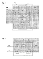
- FIG. 1 shows an inventive arrangement of a graphics controller 2, a pixel clock generator 3 and a comparison unit 4.
- the graphics controller 2 reads a video input signal which at least the required signals B-In for driving the individual pixels and a vertical and a horizontal input synchronization signal V-In and H In, and outputs a video output signal converted for output on a graphics screen, which in turn is composed of at least pixel signals B-Out and vertical and horizontal output sync signals V-Out and H-Out.
- the pixel clock PT likewise read by the graphics controller 2 serves as the time base for the generation of the output synchronization signals V-Out and H-Out, their pulse frequencies Multiples of the pixel clock PT.
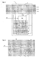
- FIG. 4 The timing diagram shows how typical waveforms can look like.
- the vertical synchronization signals V-In and V-Out are compared with each other.
- the flyback pulses 12 of the input and 13th the output synchronization signal respectively indicate the period of the image return of the input or output video image. While the return pulses of the input synchronization signal 12 always have the same length, the length of the return pulses of the Ausgangsynchronisationssignales 13 varies, which is why the pulses shown were also designated 13a and 13 b.
- the original length of the flyback pulse 13a is shortened, leading to a time shift of the phase of the signal V-out forward.
- the next following retrace pulse 13b of the signal V-Out is then earlier, ie the phase difference between V-In and V-Out has been reduced.
- the duration of the next correction period 14b is also shortened.
- the graphics controller 2 has been configured to always generate an output image refresh rate that is less than the input image refresh rate.
- T2 has a higher frequency than T1, that is generated by means of a smaller divider from the reference clock RT.
- a frequency comparator 15 is provided, which compares the generated by means of the vertical input and output synchronization signals V-In and V-Out image repetition of video input and video output with each other. As a result, a frequency comparison signal FV is then available as an additional input at the pixel clock generator 16.
Landscapes
- Engineering & Computer Science (AREA)
- Multimedia (AREA)
- Signal Processing (AREA)
- Control Of Indicators Other Than Cathode Ray Tubes (AREA)
- Controls And Circuits For Display Device (AREA)
Claims (11)
- Procédé permettant de produire un signal vidéo de sortie pouvant être édité sur un écran graphique, lequel signal vidéo de sortie sert à représenter sur l'écran graphique des images vidéo animées composées de points d'image ou pixels et de lignes, où un signal vidéo d'entrée caractérisé par une fréquence d'entrée de rafraîchissement d'image est converti pour donner le signal de sortie caractérisé par une fréquence de sortie de rafraîchissement d'image et où un signal de synchronisation horizontale d'entrée et, respectivement, un signal de synchronisation horizontale de sortie destiné à initier un retour de balayage horizontal, ainsi qu'un signal de synchronisation verticale d'entrée et, respectivement, un signal de synchronisation verticale de sortie destiné à initier un retour de balayage vertical correspondent au signal vidéo d'entrée et, respectivement, au signal vidéo de sortie et où le signal de synchronisation horizontale de sortie et le signal de synchronisation verticale de sortie sont produits sur la base d'une fréquence d'horloge des pixels, caractérisé par les phases:- comparaison du signal de synchronisation horizontale d'entrée (H-In) avec le signal de synchronisation horizontale de sortie (H-Out) et/ou du signal de synchronisation verticale d'entrée (V-In) avec le signal de synchronisation verticale de sortie (V-Out) en vue de déterminer un intervalle de temps de correction chaque fois que le signal de synchronisation horizontale de sortie (H-Out) indique un retour de balayage horizontal et est, en même temps, différent du signal de synchronisation horizontale d'entrée (H-In) ou que le signal de synchronisation verticale de sortie (V-Out) indique un retour de balayage vertical et est, en même temps, différent du signal de synchronisation verticale d'entrée (V-In),- modification de la fréquence d'horloge des pixels (PT) pendant l'intervalle de temps de correction respectif.
- Procédé selon la revendication 1, caractérisé par le fait que la fréquence d'horloge des pixels (PT) est permutée entre au moins deux valeurs données fixes (T1, T2).
- Procédé selon l'une des revendications précédentes caractérisé par le fait que, en plus, la fréquence d'entrée de rafraîchissement d'image et la fréquence de sortie de rafraîchissement d'image sont comparées l'une à l'autre et que la fréquence d'horloge des pixels (PT) est augmentée pendant l'intervalle de temps de correction respectif, si la fréquence de sortie de rafraîchissement d'image est inférieure à la fréquence d'entrée de rafraîchissement d'image correspondante.
- Procédé selon l'une des revendications précédentes caractérisé par le fait que, en plus, la fréquence d'entrée de rafraîchissement d'image et la fréquence de sortie de rafraîchissement d'image sont comparées l'une à l'autre et que la fréquence d'horloge des pixels (PT) est diminuée pendant l'intervalle de temps de correction respectif, si la fréquence de sortie de rafraîchissement d'image est supérieure à la fréquence d'entrée de rafraîchissement d'image correspondante.
- Procédé selon l'une des revendications précédentes caractérisé par le fait que, pour la détermination de l'intervalle de temps de correction, le signal de synchronisation d'entrée (H-In, V-In) est d'abord inverti et, ensuite, combiné logiquement au signal de synchronisation de sortie (H-Out, V-Out) correspondant par l'intermédiaire d'une porte logique NOR (7).
- Dispositif permettant de produire un signal vidéo de sortie pouvant être édité sur un écran graphique, lequel signal vidéo de sortie sert à représenter sur l'écran graphique des images vidéo animées composées de points d'image ou pixels et de lignes, ledit dispositif comportant un contrôleur graphique destiné à convertir un signal vidéo d'entrée caractérisé par une fréquence d'entrée de rafraîchissement d'image pour donner le signal vidéo de sortie caractérisé par une fréquence de sortie de rafraîchissement d'image, où le contrôleur graphique lit des signaux de synchronisation horizontale et des signaux de synchronisation verticale d'entrée et produit et délivre, sur la base d'une fréquence d'horloge des pixels, des signaux de synchronisation horizontale et des signaux de synchronisation verticale de sortie, où les signaux de synchronisation horizontale servent à initier un retour de balayage horizontal et les signaux de synchronisation verticale servent à initier un retour de balayage vertical, caractérisé par- un comparateur (4) relié au contrôleur graphique (2), lequel comparateur compare le signal de synchronisation horizontale d'entrée (H-In) au signal de synchronisation horizontale de sortie (H-Out) et/ou le signal de synchronisation verticale d'entrée (V-In) au signal de synchronisation verticale de sortie (V-Out) et génère un signal de comparaison horizontale (HV) et/ou un signal de comparaison verticale (VV), qui indique alors, dans chaque cas, un intervalle de temps de correction, lorsque le signal de synchronisation horizontale de sortie (H-Out) indique un retour de balayage horizontal et, en même temps, est différent du signal de synchronisation horizontale d'entrée (H-In) ou lorsque le signal de synchronisation verticale de sortie (V-Out) indique un retour de balayage vertical et, en même temps, est différent du signal de synchronisation verticale d'entrée (VIn), et- un générateur de fréquence d'horloge (3) pour les pixels qui lit le signal de comparaison horizontale (HV) et/ou le signal de comparaison verticale (VV) et délivre la fréquence d'horloge (PT) pour les pixels au contrôleur graphique (2), où le générateur de fréquence d'horloge (3) pour les pixels modifie, pendant l'intervalle de temps de correction respectif, la fréquence d'horloge (PT) pour les pixels.
- Dispositif selon la revendication 6, caractérisé par le fait que le générateur de fréquence d'horloge (3) pour les pixels permute la fréquence d'horloge (PT) pour les pixels entre au moins deux valeurs données fixes (T1, T2).
- Dispositif selon l'une des revendications précédentes 6 ou 7, caractérisé par le fait que le générateur de fréquence d'horloge (3) pour les pixels augmente la fréquence d'horloge (PT) pour les pixels pendant l'intervalle de temps de correction si la fréquence de sortie de rafraîchissement d'image est inférieure à la fréquence d'entrée de rafraîchissement d'image correspondante.
- Dispositif selon l'une des revendications précédentes 6 à 8, caractérisé par le fait que le générateur de fréquence d'horloge (3) diminue la fréquence d'horloge (PT) pour les pixels pendant l'intervalle de temps de correction si la fréquence de sortie de rafraîchissement d'image est supérieure à la fréquence d'entrée de rafraîchissement d'image correspondante.
- Dispositif selon l'une des revendications précédentes 6 à 9, caractérisé par le fait qu'il existe, en outre, un comparateur de fréquence (15), lequel compare l'une à l'autre la fréquence d'entrée de rafraîchissement d'image et la fréquence de sortie de rafraîchissement d'image et envoie le résultat au générateur de fréquence d'horloge (3) pour les pixels.
- Dispositif selon l'une des revendications précédentes 6 à 10, caractérisé par le fait que le comparateur renferme un inverseur (5) destiné à invertir le signal de synchronisation d'entrée (H-In, V-In), ainsi qu'une porte logique NOR (7) destinée à combiner logiquement la sortie de l'inverseur (5) au signal de synchronisation de sortie (H-Out, V-Out) correspondant.
Applications Claiming Priority (2)
| Application Number | Priority Date | Filing Date | Title |
|---|---|---|---|
| DE2003139661 DE10339661B4 (de) | 2003-08-28 | 2003-08-28 | Verfahren und Anordnung zur Synchronisation eines Videoeingangs- mit einem Videoausgangssignal |
| DE10339661 | 2003-08-28 |
Publications (2)
| Publication Number | Publication Date |
|---|---|
| EP1511003A1 EP1511003A1 (fr) | 2005-03-02 |
| EP1511003B1 true EP1511003B1 (fr) | 2009-05-06 |
Family
ID=34089237
Family Applications (1)
| Application Number | Title | Priority Date | Filing Date |
|---|---|---|---|
| EP20040103464 Expired - Lifetime EP1511003B1 (fr) | 2003-08-28 | 2004-07-21 | Procédé et dispositif pour la synchronisation d'un signal vidéo de sortie avec un signal vidéo d'entrée |
Country Status (2)
| Country | Link |
|---|---|
| EP (1) | EP1511003B1 (fr) |
| DE (2) | DE10339661B4 (fr) |
Family Cites Families (12)
| Publication number | Priority date | Publication date | Assignee | Title |
|---|---|---|---|---|
| AU6713696A (en) * | 1995-08-01 | 1997-02-26 | Auravision Corporation | Transition aligned video synchronization system |
| JP3307807B2 (ja) * | 1995-09-29 | 2002-07-24 | 三洋電機株式会社 | 映像信号処理装置 |
| US5929924A (en) * | 1997-03-10 | 1999-07-27 | Neomagic Corp. | Portable PC simultaneously displaying on a flat-panel display and on an external NTSC/PAL TV using line buffer with variable horizontal-line rate during vertical blanking period |
| JP3770360B2 (ja) * | 1998-03-18 | 2006-04-26 | シャープ株式会社 | 液晶表示装置及びその制御回路並びに液晶表示パネル駆動方法 |
| WO2001001386A1 (fr) * | 1999-06-30 | 2001-01-04 | Aurora Systems | Affichage a cristaux liquides multistandard avec ajustement automatique du signal de reglage |
| US6522365B1 (en) * | 2000-01-27 | 2003-02-18 | Oak Technology, Inc. | Method and system for pixel clock recovery |
| TW461218B (en) * | 2000-02-24 | 2001-10-21 | Acer Peripherals Inc | Digital image display which can judge the picture image resolution based on the clock frequency of the pixel |
| US6747656B2 (en) * | 2000-04-07 | 2004-06-08 | Sony Corporation | Image processing apparatus and method of the same, and display apparatus using the image processing apparatus |
| US6316974B1 (en) * | 2000-08-26 | 2001-11-13 | Rgb Systems, Inc. | Method and apparatus for vertically locking input and output signals |
| JP2003116110A (ja) * | 2001-10-03 | 2003-04-18 | Sony Corp | 画像信号処理方法及び画像信号処理装置 |
| JP3580792B2 (ja) * | 2001-12-12 | 2004-10-27 | 沖電気工業株式会社 | ビデオ信号検出回路 |
| TW536870B (en) * | 2002-01-25 | 2003-06-11 | Via Tech Inc | Device and method for generating clock signals |
-
2003
- 2003-08-28 DE DE2003139661 patent/DE10339661B4/de not_active Expired - Fee Related
-
2004
- 2004-07-21 EP EP20040103464 patent/EP1511003B1/fr not_active Expired - Lifetime
- 2004-07-21 DE DE200450009446 patent/DE502004009446D1/de not_active Expired - Fee Related
Also Published As
| Publication number | Publication date |
|---|---|
| DE10339661A1 (de) | 2005-03-31 |
| DE10339661B4 (de) | 2006-07-27 |
| EP1511003A1 (fr) | 2005-03-02 |
| DE502004009446D1 (de) | 2009-06-18 |
Similar Documents
| Publication | Publication Date | Title |
|---|---|---|
| DE69604969T2 (de) | Verfahren und Einrichtung zur Synchronisierung von Videodaten und graphischen Daten in einem Multimediaanzeigesystem mit einem gemeinsamen Rasterpufferspeicher | |
| DE69637276T2 (de) | Bildanzeigegerät | |
| DE69015536T2 (de) | Fensterdehnung für Farbfernsehen und Korrektur der Überabtastung für hochauflösende Rastergraphikanzeigen. | |
| DE4332573C2 (de) | Videographiksystem zum Anzeigen von Signalverläufen auf einem Videomonitor | |
| DE69221569T2 (de) | Videosignalverarbeitungsschaltung mit Bildvergrösserungsfunktion | |
| DE3787914T2 (de) | Digitaler Videogenerator. | |
| DE69218476T2 (de) | Frequenzgenerator für eine Synchronverriegelung | |
| DE3223658C2 (de) | System und Verfahren zur Umwandlung eines zwischenzeilenlosen Videosignals in ein Zwischenzeilenvideosignal | |
| DE69033156T2 (de) | Bildschirmanzeige an einem Fernsehempfänger | |
| DE19810062C2 (de) | Synchronisation einer links/rechts-Kanalanzeige und vertikale Auffrischung in stereoskopischen Mehranzeigencomputergraphiksystemen | |
| DE112011105224B4 (de) | Bildinformations-Wiedergabeeinheit, Bildinformations-Wiedergabevorrichtung und Synchronisationskontrollverfahren | |
| DE3854562T2 (de) | Demultiplexer für Computervideo. | |
| DE69412887T2 (de) | Verfahren zur Synchronisierung von Videomodulation mit konstanter Zeitbasis | |
| DE2510542A1 (de) | Digitale bildwiedergabevorrichtung mit mehreren bildschirmen | |
| DE4327779C1 (de) | Verfahren und Schaltungsanordnung für ein Fernsehgerät zur Verminderung des Flimmerns | |
| DE19545356A1 (de) | Verfahren und Vorrichtung zur Überlagerung von Stereo-Videobildern | |
| DE69606947T2 (de) | Nichtlineare bildformatanpassung | |
| DE3624191C2 (fr) | ||
| DE102006009010B4 (de) | Vorrichtung und Verfahren zur Ausgabe von unterschiedlichen Bildern auf wenigstens zwei Anzeigen | |
| DE19962730C2 (de) | Videosignalverarbeitungssystem bzw. Videosignalverarbeitungsverfahren | |
| EP0500147A2 (fr) | Méthode et dispositif de commande d'un moniteur | |
| DE69431827T2 (de) | Bildwiedergabevorrichtung und -verfahren und rechner. | |
| DE10339661B4 (de) | Verfahren und Anordnung zur Synchronisation eines Videoeingangs- mit einem Videoausgangssignal | |
| DE69117848T2 (de) | Verfahren und Einrichtung zum Steuern eines Anzeigegeräts | |
| DE69825125T2 (de) | Verfahren und Vorrichtung zur Bildformatumwandlung |
Legal Events
| Date | Code | Title | Description |
|---|---|---|---|
| PUAI | Public reference made under article 153(3) epc to a published international application that has entered the european phase |
Free format text: ORIGINAL CODE: 0009012 |
|
| AK | Designated contracting states |
Kind code of ref document: A1 Designated state(s): AT BE BG CH CY CZ DE DK EE ES FI FR GB GR HU IE IT LI LU MC NL PL PT RO SE SI SK TR |
|
| AX | Request for extension of the european patent |
Extension state: AL HR LT LV MK |
|
| 17P | Request for examination filed |
Effective date: 20050321 |
|
| AKX | Designation fees paid |
Designated state(s): DE FR GB IT |
|
| RAP1 | Party data changed (applicant data changed or rights of an application transferred) |
Owner name: CONTINENTAL AUTOMOTIVE GMBH |
|
| GRAP | Despatch of communication of intention to grant a patent |
Free format text: ORIGINAL CODE: EPIDOSNIGR1 |
|
| GRAS | Grant fee paid |
Free format text: ORIGINAL CODE: EPIDOSNIGR3 |
|
| GRAA | (expected) grant |
Free format text: ORIGINAL CODE: 0009210 |
|
| AK | Designated contracting states |
Kind code of ref document: B1 Designated state(s): DE FR GB IT |
|
| REG | Reference to a national code |
Ref country code: GB Ref legal event code: FG4D Free format text: NOT ENGLISH |
|
| REF | Corresponds to: |
Ref document number: 502004009446 Country of ref document: DE Date of ref document: 20090618 Kind code of ref document: P |
|
| PLBE | No opposition filed within time limit |
Free format text: ORIGINAL CODE: 0009261 |
|
| STAA | Information on the status of an ep patent application or granted ep patent |
Free format text: STATUS: NO OPPOSITION FILED WITHIN TIME LIMIT |
|
| 26N | No opposition filed |
Effective date: 20100209 |
|
| REG | Reference to a national code |
Ref country code: FR Ref legal event code: ST Effective date: 20100331 |
|
| GBPC | Gb: european patent ceased through non-payment of renewal fee |
Effective date: 20090806 |
|
| PG25 | Lapsed in a contracting state [announced via postgrant information from national office to epo] |
Ref country code: FR Free format text: LAPSE BECAUSE OF NON-PAYMENT OF DUE FEES Effective date: 20090731 |
|
| PG25 | Lapsed in a contracting state [announced via postgrant information from national office to epo] |
Ref country code: DE Free format text: LAPSE BECAUSE OF NON-PAYMENT OF DUE FEES Effective date: 20100202 |
|
| PG25 | Lapsed in a contracting state [announced via postgrant information from national office to epo] |
Ref country code: GB Free format text: LAPSE BECAUSE OF NON-PAYMENT OF DUE FEES Effective date: 20090806 |
|
| PG25 | Lapsed in a contracting state [announced via postgrant information from national office to epo] |
Ref country code: IT Free format text: LAPSE BECAUSE OF FAILURE TO SUBMIT A TRANSLATION OF THE DESCRIPTION OR TO PAY THE FEE WITHIN THE PRESCRIBED TIME-LIMIT Effective date: 20090506 |