EP1510992A2 - Vorrichtung mit dynamischer LED-Anzeige, insbesondere für den Aussenbereich des öffentlichen Personennahverkehrs - Google Patents
Vorrichtung mit dynamischer LED-Anzeige, insbesondere für den Aussenbereich des öffentlichen Personennahverkehrs Download PDFInfo
- Publication number
- EP1510992A2 EP1510992A2 EP04019343A EP04019343A EP1510992A2 EP 1510992 A2 EP1510992 A2 EP 1510992A2 EP 04019343 A EP04019343 A EP 04019343A EP 04019343 A EP04019343 A EP 04019343A EP 1510992 A2 EP1510992 A2 EP 1510992A2
- Authority
- EP
- European Patent Office
- Prior art keywords
- outer housing
- frame
- housing
- sides
- inner housing
- Prior art date
- Legal status (The legal status is an assumption and is not a legal conclusion. Google has not performed a legal analysis and makes no representation as to the accuracy of the status listed.)
- Withdrawn
Links
Images




Classifications
-
- G—PHYSICS
- G09—EDUCATION; CRYPTOGRAPHY; DISPLAY; ADVERTISING; SEALS
- G09F—DISPLAYING; ADVERTISING; SIGNS; LABELS OR NAME-PLATES; SEALS
- G09F21/00—Mobile visual advertising
- G09F21/04—Mobile visual advertising by land vehicles
Definitions
- the invention relates to a device with dynamic LED display for outdoor or indoor use with a housing with single-sided or double-sided LED display and one in it arranged control computer and a power supply, in particular for the public transport, being a circulating narrow frame of the case of two transparent panes is covered and related to control semiconductors LED modules are mounted on a mounting plate.
- this device has as disadvantageous exposed the considerable storage costs, because always only complete devices could be stored in stock, as alone on the LED display panels by means of double-sided adhesive Transparency glued on transparent panels with a Setting time of the glue are subject to two days and only ever put finished, no longer changeable devices in stock could become.
- U 1 is a further device of discloses at the beginning of the type mentioned, in which in an im Cross-section of trapezoidal housing components, such as light-emitting diodes, Circuit boards, power sources, power and more mechanical and electrical components are arranged, as commonly used for traffic information displays / displays be used.
- the housing is on both sides of a closed transparent cover.
- These Covering device which in a known, actual Embodiment of this device by means of the upper edge of the housing mounted hinged joints designed hinged, consists of an outer surface and an inner display surface.
- the outer surface is covered with a color film of molten glass Mistake.
- the inner display surface consists of a layer or a film of transparent material made of melted glass.
- the inner display area is of a circumferential, opaque frame framed as paspartout. Thereby inevitably reduces the display area of the Covering device to the light-emitting diodes arranged in the housing.
- the case is extremely bulky. In a repair must Cover device folded up or otherwise removed to for repair purposes access to the interior of the housing to accomplish. In particular, the renewed proves to be critical Sealing of the cover on the housing opposite Rainfall. After a replacement of the cover As a closure of the housing must by no means a tightness of the Be given housing.
- the invention has the object, a device of to create the aforementioned type, while maintaining a small depth and an effective waterproofness nevertheless a non-destructive access to the interior, For example, for repair purposes, as guaranteed as a secure static mounting of the LED modules as well as a considerable reduced storage costs.
- Inner housing with two LED display panels in the form of the Mounting plates for each of the two transparent panes of the Exterior housing provided on at least their four Corner areas have a coupling pin with which they to its two opposite sides detachable in one as Spacer trained coupling element are inserted.
- This allows the compact mounting plates of the Inner housing by means of a simple plug-in form a cube designed as a coupling element with each other be coupled.
- the LED modules and their control semiconductors means a thermally conductive, double-sided adhesive film with a board mounted on heat sinks, which are embedded in the latter and attached to it threaded bolt and coupling tabs with the same Groove bolted together to form a compact mounting plate are.
- bracket plate such as For example, in the subject of DE 298 19 742 U1, thereby dispensable that the heat sink of the LED modules themselves with the Connecting straps converted into a mounting frame be by in this heat sink threaded bolts are embedded, the with their screw surfaces from the surface of the heat sink protrude and there by joints equal joints are bolted together to form a compact mounting plate. This can be done by any stringing together of the LED modules these on their heat sink side to relatively long and wide LED scoreboards are bolted together.
- This special Training also has the advantage that with the power supply and the control computer connected carrier plates also off Metal are made and made with an aluminum alloy existing heat sinks for heat dissipation of heat from both the LED modules and those of the power supply and Control computer can be used and to ensure a correspondingly large thermal mass transport with the metallic ones Frame sides of the outer housing are thermally conductively connected.
- the fourth frame side with the adjacent frame ends of the Outer housing via countersunk screws and a female thread as well connected to a coupling element, and the screws are of by means of a two-component adhesive glued metal angles covered to prevent unauthorized access.
- the outer housing gives the unbiased viewer a picture a non-openable outer casing.
- a releasable sealant is between the fourth Frame side and the adjacent edges of the transparent Washers and the adjacent frame ends of the outer housing a silicone strip provided.
- the transparent discs of the outer housing on its inside with a transparent color foil occupied. Besides, they are on theirs Outside provided with a two-component glass paint to on the one hand, contrast-sharp contours of the LED display ensure, on the other hand, after a surprising Determination of the Erfmders this glass varnish thermally insulating, especially with a vertical impact of sunbeams.
- the outer housing is advantageous via a screw or Plug-in connection releasably attached to a holder, be it on one Gallows or within an information column or other Mounts, as described for example in DE 102 07 264 C 1 is shown.
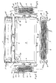
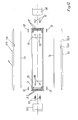
- the device 1 is made a narrow peripheral frame 2a of an outer casing 2, consisting of a total of two longitudinal frame sides 3, 4 and two narrow frame sides 5, 6 composed.
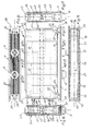
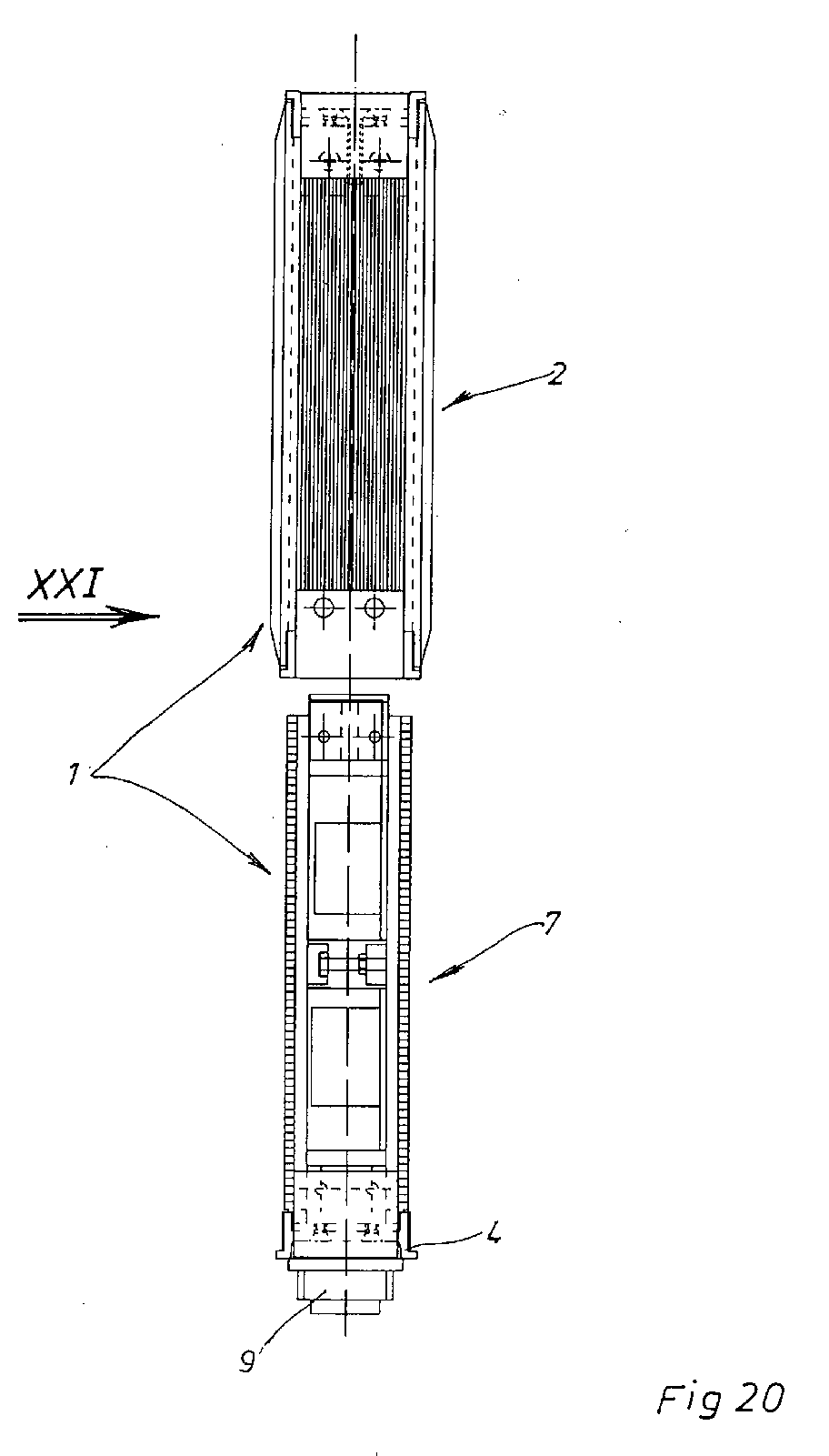
- On the bottom Longitudinal side 4 is that of Figures 13 to 17 and 20th and 21 apparent inner housing 7 elevated and thus over screws to be described firmly screwed.
- All frame sides 3, 4, 5, 6 are at their end portions Mitred cut and inserted there in 15 in Connection with screws 16 (see Fig. 1) to a circumferential, closed frame 2a connected.
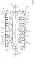
- the From Figures 18 and 19 apparent light-emitting diodes 17 with their Control semiconductors and their boards by means of a thermally conductive, Double-sided adhesive, not shown here on film Heatsink 18 set of an aluminum alloy. hereby arise strip LED modules 19. Between the not shown, because not visible board and the heat sinks 18th are the heads of screws 20 inserted, which with their Screw shaft penetrate the heat sink 18 in openings and protrude beyond the outer surface, as it is the figures 18 and 19 can be removed.
- the LED modules 19 with the same joints 21 and Therefore, the same way over the coupling tabs 22 means Screws 23 to a compact support plate 24 with each other screwed.
- On in the corner regions of the support plate 24th located screws 20 are small cylinder 27 with Screwed internal thread, which thereby a Coupling pin 28 for a yet to be described Form plug connection.
- the holes 32 are in the cubic coupling elements 33 in the lower Corner areas formed as slots.
- angles 15 in the two lower corner areas can fastened with their horizontal legs by screws 34 be at the same time in the associated coupling elements 33rd engage in a retaining manner (see Fig. 13).
- angles 36 be by means of an adhesive, not shown on the Corner areas glued and thus block each unauthorized User access to the screws 16 and 35.
- angles 36 To release be the angles 36 in a workshop with a single Hammer hit off and then in reverse order the inner housing 7 from the outer housing 2 by loosening the Screw 16, 35 dismantled without an inner part of the Inner housing 7 or the outer housing 2 must take damage.
- the power supply 40 and the control computer 41 shown as a block, because whose items are not of interest here.
- the power supply 40 and the control computer 41 can both directly on the heat sinks 18th the LED modules 19 as well as on a separate Carrier plate 42, 43 are arranged to over this Carrier plate 42, 43 a corresponding heat dissipation to the four frame sides 3 to 6 of the outer housing 2 with the Cooling fins 37 ensure what is not the subject of this Invention is.
- the gist of the invention may be summarized as follows: By creating a book like a book as a plug-in unit designed inner housing 7 in an outer housing 2 may be a compact design can be maintained. At the same time both the Inner housing 7 and the outer housing 2 non-destructive in their Parts are disassembled without any of the components doing damage takes.
- each one here used LED modules 19 existing heat sink as a support frame Not only can a compact mounting plate 24, but also one compared to conventional LED modules with separate Mounting plates can be ensured even lighter version, because the previously required mounting plates are missing. And finally access to the screws 16 and 35 in the corner areas by the glued angle 36 an unauthorized user locked, but this does not complicate the dismantling.
Landscapes
- Business, Economics & Management (AREA)
- Accounting & Taxation (AREA)
- Marketing (AREA)
- Physics & Mathematics (AREA)
- General Physics & Mathematics (AREA)
- Engineering & Computer Science (AREA)
- Theoretical Computer Science (AREA)
- Casings For Electric Apparatus (AREA)
- Traffic Control Systems (AREA)
Abstract
Description
- Vorrichtung
- 1
- Außengehäuse
- 2
- Rahmen
- 2a
- Längsseiten des Rahmens 2a
- 3, 4
- kurze Rahmenseiten
- 5, 6
- Innengehäuse
- 7
- Steckdosen
- 8, 9
- Scheiben
- 10, 11
- Innenfläche der Scheiben 10, 11
- 10a, 11a
- Außenfläche der Scheiben 10, 11
- 10b, 11b
- Dichtungsstreifen
- 12
- lösbares Dichtungsmittel
- 12a
- Farbfolien
- 13, 14
- Innenwinkel
- 15
- Schrauben
- 16, 23, 34, 35
- Leuchtdioden
- 17
- Kühlkörper
- 18
- LED-Module
- 19
- Gewindebolzen
- 20
- Fugen
- 21
- Kupplungslaschen
- 22
- Halterungsplatten
- 24
- Außenfläche der Halterungsplatte 24
- 25
- Innenseite der Halterungsplatte 24
- 26
- Zylinder
- 27
- Kupplungszapfen
- 28
- Muttern
- 29
- Schraubbolzen
- 30
- Kontermuttern
- 31
- Ausnehmung
- 32
- Kupplungselemente
- 33
- Winkel
- 36
- Kühlrippen
- 37
- Kupplungsstecker
- 38, 39
- Netzteil
- 40
- Steuerrechner
- 41
- Trägerblech
- 42, 43
Claims (16)
- Vorrichtung mit dynamischer LED-Anzeige für den Außenoder Innenbereich mit einem Gehäuse mit einseitiger oder beidseitiger LED-Anzeige und einem darin angeordneten Steuerrechner und einem Netzteil, insbesondere für den öffentlichen Personennahverkehr, wobei ein umlaufender schmaler Rahmen des Gehäuses von zwei transparenten Scheiben abgedeckt ist und die mit Steuerhalbleitern in Verbindung stehenden LED-Module auf einer Halterungsplatte befestigt sind, gekennzeichnet durch folgende Merkmale,a) die Vorrichtung (1) weist ein Außengehäuse (2) und ein Innengehäuse (7) auf,b) das Außengehäuse (2) besteht aus einem schmalen, an drei Seiten (5, 3, 6) geschlossenen Rahmen (2a), auf dessen vierter Rahmenseite (4) das Innengehäuse (7) lösbar aufgeständert und befestigt ist,c) die beiden transparenten Scheiben (10, 11) des Außengehäuses (2) sind über eine Dichtung (12) mit den drei Seiten (5, 3, 6) des Rahmens verbunden, undd) das Innengehäuse (7) ist von den mit den LED-Modulen (19) bestückten Halterungsplatten (24) gebildet, die lösbar mit der vierten Rahmenseite (4) des Außengehäuses (2) verbunden und diese nach Einschub des Innengehäuses (7) in das Außengehäuse (2) mit den beiden angrenzenden Rahmenenden des Außengehäuses (2) über ein lösbares Dichtungsmittel (12a) verschraubt ist.
- Vorrichtung nach Anspruch 1, dadurch gekennzeichnet, daß das Innengehäuse (7) mit zwei LED-Anzeigetafeln in Form der Halterungsplatten (24) für jede der beiden transparenten Scheiben (10, 11) des Außengehäuses (2) versehen ist, die an mindestens ihren vier Eckenbereichen einen Kupplungszapfen (28) aufweisen, mit denen sie an ihren beiden gegenüberliegenden Seiten lösbar in ein als Distanzhalter ausgebildetes Kupplungselement (33) gesteckt sind.
- Vorrichtung nach Anspruch 1 und 2, dadurch gekennzeichnet, daß im Zwischenraum zwischen den beiden Halterungsplatten (24) auf je einer mit den Halterungsplatten (24) und/oder mindestens einer der Rahmenseiten (3-6) des Außengehäuses (2) verbundenen Trägerplatte (42, 43) einmal das Netzteil (40) und einmal der Steuerrechner (41) angeordnet ist.
- Vorrichtung nach einem der Ansprüche 1 bis 3, dadurch gekennzeichnet, daß die LED-Module (19) sowie ihre Steuerhalbleiter mittels einer wärmeleitenden, doppelseitig klebenden Folie mit einer Platine auf Kühlkörpern (18) befestigt sind, die über in letztere eingelassene und daran gehalterte Gewindebolzen (20) und Kupplungslaschen (22) mit gleicher Fuge (21) miteinander zu einer kompakten Halterungsplatte (24) verschraubt sind.
- Vorrichtung nach einem der Ansprüche 1 bis 4, dadurch gekennzeichnet, daß die vierte Rahmenseite (4) mit den angrenzenden Rahmenenden des Außengehäuses (2) über Senkschrauben (16) und einem Innenwinkel (15) sowie einem Kupplungselement (33) verbunden ist und die Schrauben (15, 34, 35) von mittels eines Zweikomponentenklebers aufgeklebten Metallwinkeln (36) abgedeckt sind.
- Vorrichtung nach einem der Ansprüche 1 bis 5, dadurch gekennzeichnet, daß drei Rahmenseiten (5, 3, 6) des Außengehäuses (2) an ihren auf Gehrung geschnittenen Seitenenden entweder zusammengeklebt, zusammengeschweißt oder unter Zwischenlegung einer Dichtung über einen Innenwinkel (15) mit Schrauben (16, 34) verbunden sind.
- Vorrichtung nach Anspruch 6, dadurch gekennzeichnet, daß bei einer Verbindung der Seitenenden mit Schrauben (16, 34) diese als Senkschrauben ausgebildet und von einem aufgeklebten Metallwinkel (36) abgedeckt sind.
- Vorrichtung nach einem der Ansprüche 2 bis 7, dadurch gekennzeichnet, daß die Kupplungselemente (33) zwischen den beiden kompakten Halterungsplatten (24) der LED-Module (19) in der Nähe der vierten Rahmenseite (4) mit dieser zu einer festen Schubeinheit verschraubt sind.
- Vorrichtung nach einem der Ansprüche 1 bis 8, dadurch gekennzeichnet, daß auch an den von der vierten Rahmenseite (4) des Außengehäuses (2) abgewandten Eckenbereichen des Innengehäuses (7) Kupplungselemente (33) zwischen den beiden kompakten Halterungsplatten (24) vorgesehen sind, an welchen die Eckenbereiche über Kupplungszapfen (28) gehaltert sind.
- Vorrichtung nach einem der Ansprüche 1 bis 9, dadurch gekennzeichnet, daß als lösbares Dichtungsmittel zwischen der vierten Rahmenseite (4) und den angrenzenden Kanten der transparenten Scheiben (10, 11) sowie den angrenzenden Rahmenenden des Außengehäuses (2) ein Silikonstreifen (12a) vorgesehen ist.
- Vorrichtung nach einem der Ansprüche 1 bis 10, dadurch gekennzeichnet, daß das Netzteil (40) und der Steuerrechner (41) im Innengehäuse (7) über lösbare elektrische Steckkupplungen miteinander, mit den LED-Modulen (19) sowie mit weiteren Einbaukomponenten, wie Minikameras, Sensoren, Empfangs-Sendeeinheiten, Lautsprecher und Mikrofonen, verbunden sind.
- Vorrichtung nach einem der Ansprüche 1 bis 11, dadurch gekennzeichnet, daß die transparenten Scheiben (10, 11) des Außengehäuses (2) auf ihrer Innenseite (10a, 11a) mit einer transparenten Farbfolie (13, 14) belegt sind.
- Vorrichtung nach einem der Ansprüche 1 bis 12, dadurch gekennzeichnet, daß die transparenten Scheiben (10, 11) des Außengehäuses (2) auf ihrer Außenseite (10b, 11b) mit einem Zweikomponenten-Glaslack versehen sind.
- Vorrichtung nach einem der Ansprüche 1 bis 13, dadurch gekennzeichnet, daß die vierte, mit dem Innengehäuse (7) lösbar gekuppelte Rahmenseite (4) mit zwei wasserdichten Steckdosen (8, 9) versehen ist, von denen die eine in an sich bekannter Weise mit einer elektrischen Datenversorgungsleitung und die andere mit einer elektrischen Energieversorgungsleitung zu kuppeln ist.
- Vorrichtung nach einem der Ansprüche 1 bis 14, dadurch gekennzeichnet, daß sämtliche Außenflächen der umlaufenden, aus einer Aluminiumlegierung bestehenden Rahmenseiten (3-6) des Außengehäuses (2) mit stoffschlüssig mit den Rahmenseiten (3-6) verbundenen Rippen (37) versehen sind.
- Vorrichtung nach einem der Ansprüche 1 bis 15, dadurch gekennzeichnet, daß das Außengehäuse (2) über Schraub- oder Steckverbindungen lösbar an einer Halterung befestigt ist.
Applications Claiming Priority (2)
| Application Number | Priority Date | Filing Date | Title |
|---|---|---|---|
| DE2003139413 DE10339413B3 (de) | 2003-08-27 | 2003-08-27 | Vorrichtung mit dynamischer LED-Anzeige, insbesondere für den Außenbereich des öffentlichen Personennahverkehrs |
| DE10339413 | 2003-08-27 |
Publications (2)
| Publication Number | Publication Date |
|---|---|
| EP1510992A2 true EP1510992A2 (de) | 2005-03-02 |
| EP1510992A3 EP1510992A3 (de) | 2006-03-29 |
Family
ID=32864530
Family Applications (1)
| Application Number | Title | Priority Date | Filing Date |
|---|---|---|---|
| EP04019343A Withdrawn EP1510992A3 (de) | 2003-08-27 | 2004-08-14 | Vorrichtung mit dynamischer LED-Anzeige, insbesondere für den Aussenbereich des öffentlichen Personennahverkehrs |
Country Status (2)
| Country | Link |
|---|---|
| EP (1) | EP1510992A3 (de) |
| DE (1) | DE10339413B3 (de) |
Cited By (1)
| Publication number | Priority date | Publication date | Assignee | Title |
|---|---|---|---|---|
| CN112634760A (zh) * | 2020-12-22 | 2021-04-09 | 上海冠凯软件技术有限公司 | 一种自动化测试工具数据建模展示装置 |
Families Citing this family (1)
| Publication number | Priority date | Publication date | Assignee | Title |
|---|---|---|---|---|
| RU201096U1 (ru) * | 2020-06-29 | 2020-11-26 | Виктор Людвигович Поляков | Корпус-радиатор монитора |
Family Cites Families (3)
| Publication number | Priority date | Publication date | Assignee | Title |
|---|---|---|---|---|
| DE29819742U1 (de) * | 1998-10-01 | 1999-01-07 | Lumino Licht Elektronik GmbH, 47799 Krefeld | Einrichtung zur Anzeige von alpha-nummerischen und/oder Bildzeichen |
| DE10207264C1 (de) * | 2002-02-21 | 2003-06-26 | Line Elektro Electronic Gmbh E | Vorrichtung mit dynamischer LED-Anzeige für den Außenbereich des öffentlichen Personennahverkehrs |
| DE20313263U1 (de) * | 2003-08-27 | 2003-11-13 | provi GmbH, 09661 Hainichen | Vorrichtung mit dynamischer LED-Anzeige, insbesondere für den Außenbereich des öffentlichen Personennahverkehr |
-
2003
- 2003-08-27 DE DE2003139413 patent/DE10339413B3/de not_active Expired - Fee Related
-
2004
- 2004-08-14 EP EP04019343A patent/EP1510992A3/de not_active Withdrawn
Cited By (1)
| Publication number | Priority date | Publication date | Assignee | Title |
|---|---|---|---|---|
| CN112634760A (zh) * | 2020-12-22 | 2021-04-09 | 上海冠凯软件技术有限公司 | 一种自动化测试工具数据建模展示装置 |
Also Published As
| Publication number | Publication date |
|---|---|
| EP1510992A3 (de) | 2006-03-29 |
| DE10339413B3 (de) | 2004-09-16 |
Similar Documents
| Publication | Publication Date | Title |
|---|---|---|
| DE69525664T2 (de) | Vorrichtung zum Ausrichten von Anzeigemodulen | |
| EP1346822A1 (de) | Gebäudedachelement | |
| EP0676160B1 (de) | Vorrichtung zur Zurschaustellung von flachen Gegenständen | |
| WO2009080758A1 (de) | Rahmen mit integrierter beleuchtung und stromversorgung | |
| DE19515122A1 (de) | Schaltschrank mit Baugruppen | |
| DE102014010278A1 (de) | Sektionaltorblatt | |
| DE19709460C2 (de) | Freiluftgehäuse | |
| DE2160513A1 (de) | Stern system (profilstangen und stromprofile als einheitliches bausystem) | |
| DE10339413B3 (de) | Vorrichtung mit dynamischer LED-Anzeige, insbesondere für den Außenbereich des öffentlichen Personennahverkehrs | |
| DE20313263U1 (de) | Vorrichtung mit dynamischer LED-Anzeige, insbesondere für den Außenbereich des öffentlichen Personennahverkehr | |
| EP2834080B1 (de) | Glasverbund mit funktionselement | |
| DE10207264C1 (de) | Vorrichtung mit dynamischer LED-Anzeige für den Außenbereich des öffentlichen Personennahverkehrs | |
| DE1932380A1 (de) | Schaltungsaufbau | |
| EP3661176A1 (de) | Magnetischer blickschutzfilter | |
| DE212023000042U1 (de) | Nachrüstbarer Multifunktionaler Displaybaustein | |
| EP3918175B1 (de) | Scheibeneinheit und verfahren zur herstellung und/oder bereitstellung einer solchen scheibeneinheit | |
| DE202010001914U1 (de) | Möbelbauteil, insbesondere Möbelboden, und Möbelstück mit Möbelbauteil | |
| DE20202684U1 (de) | Vorrichtung mit dynamischer, voll graphikfähiger LED-Anzeige im Außenbereich des öffentlichen Personennahverkehrs | |
| EP0908990A2 (de) | Informations- und Kommunikationseinrichtung | |
| DE2144752A1 (de) | Werbetraeger | |
| EP3373278A1 (de) | Verkehrszeichen-modul und aus verkehrszeichen-modulen zusammengesetztes verkehrszeichen | |
| DE102017115730A1 (de) | LED-Panel mit ausschwenkbarem Steckverbinder | |
| DE10019998C2 (de) | Bausatz für eine Briefkastenanlage | |
| DE102015102424A1 (de) | Verfahren zur Herstellung zumindest eines Teils eines Möbelstücks oder eines Einrichtungsgegenstands und Möbelstück oder Einrichtungsgegenstand | |
| DE19512370A1 (de) | Scheibenleuchte |
Legal Events
| Date | Code | Title | Description |
|---|---|---|---|
| PUAI | Public reference made under article 153(3) epc to a published international application that has entered the european phase |
Free format text: ORIGINAL CODE: 0009012 |
|
| AK | Designated contracting states |
Kind code of ref document: A2 Designated state(s): AT BE BG CH CY CZ DE DK EE ES FI FR GB GR HU IE IT LI LU MC NL PL PT RO SE SI SK TR |
|
| AX | Request for extension of the european patent |
Extension state: AL HR LT LV MK |
|
| PUAL | Search report despatched |
Free format text: ORIGINAL CODE: 0009013 |
|
| AK | Designated contracting states |
Kind code of ref document: A3 Designated state(s): AT BE BG CH CY CZ DE DK EE ES FI FR GB GR HU IE IT LI LU MC NL PL PT RO SE SI SK TR |
|
| AX | Request for extension of the european patent |
Extension state: AL HR LT LV MK |
|
| AKX | Designation fees paid |
Designated state(s): AT BE BG CH CY CZ DE DK EE ES FI FR GB GR HU IE IT LI LU MC NL PL PT RO SE SI SK TR |
|
| 17P | Request for examination filed |
Effective date: 20060927 |
|
| GRAP | Despatch of communication of intention to grant a patent |
Free format text: ORIGINAL CODE: EPIDOSNIGR1 |
|
| 19U | Interruption of proceedings before grant |
Effective date: 20080131 |
|
| 19W | Proceedings resumed before grant after interruption of proceedings |
Effective date: 20081201 |
|
| RAP1 | Party data changed (applicant data changed or rights of an application transferred) |
Owner name: ISOTRONIC-SYSTEMS GMBH |
|
| GRAC | Information related to communication of intention to grant a patent modified |
Free format text: ORIGINAL CODE: EPIDOSCIGR1 |
|
| STAA | Information on the status of an ep patent application or granted ep patent |
Free format text: STATUS: THE APPLICATION IS DEEMED TO BE WITHDRAWN |
|
| 18D | Application deemed to be withdrawn |
Effective date: 20090415 |