EP1510992A2 - Dynamic graphic LED display device for outdoor use in public local passengers traffic - Google Patents
Dynamic graphic LED display device for outdoor use in public local passengers traffic Download PDFInfo
- Publication number
- EP1510992A2 EP1510992A2 EP04019343A EP04019343A EP1510992A2 EP 1510992 A2 EP1510992 A2 EP 1510992A2 EP 04019343 A EP04019343 A EP 04019343A EP 04019343 A EP04019343 A EP 04019343A EP 1510992 A2 EP1510992 A2 EP 1510992A2
- Authority
- EP
- European Patent Office
- Prior art keywords
- outer housing
- frame
- housing
- sides
- inner housing
- Prior art date
- Legal status (The legal status is an assumption and is not a legal conclusion. Google has not performed a legal analysis and makes no representation as to the accuracy of the status listed.)
- Withdrawn
Links
Images




Classifications
-
- G—PHYSICS
- G09—EDUCATION; CRYPTOGRAPHY; DISPLAY; ADVERTISING; SEALS
- G09F—DISPLAYING; ADVERTISING; SIGNS; LABELS OR NAME-PLATES; SEALS
- G09F21/00—Mobile visual advertising
- G09F21/04—Mobile visual advertising by land vehicles
Definitions
- the invention relates to a device with dynamic LED display for outdoor or indoor use with a housing with single-sided or double-sided LED display and one in it arranged control computer and a power supply, in particular for the public transport, being a circulating narrow frame of the case of two transparent panes is covered and related to control semiconductors LED modules are mounted on a mounting plate.
- this device has as disadvantageous exposed the considerable storage costs, because always only complete devices could be stored in stock, as alone on the LED display panels by means of double-sided adhesive Transparency glued on transparent panels with a Setting time of the glue are subject to two days and only ever put finished, no longer changeable devices in stock could become.
- U 1 is a further device of discloses at the beginning of the type mentioned, in which in an im Cross-section of trapezoidal housing components, such as light-emitting diodes, Circuit boards, power sources, power and more mechanical and electrical components are arranged, as commonly used for traffic information displays / displays be used.
- the housing is on both sides of a closed transparent cover.
- These Covering device which in a known, actual Embodiment of this device by means of the upper edge of the housing mounted hinged joints designed hinged, consists of an outer surface and an inner display surface.
- the outer surface is covered with a color film of molten glass Mistake.
- the inner display surface consists of a layer or a film of transparent material made of melted glass.
- the inner display area is of a circumferential, opaque frame framed as paspartout. Thereby inevitably reduces the display area of the Covering device to the light-emitting diodes arranged in the housing.
- the case is extremely bulky. In a repair must Cover device folded up or otherwise removed to for repair purposes access to the interior of the housing to accomplish. In particular, the renewed proves to be critical Sealing of the cover on the housing opposite Rainfall. After a replacement of the cover As a closure of the housing must by no means a tightness of the Be given housing.
- the invention has the object, a device of to create the aforementioned type, while maintaining a small depth and an effective waterproofness nevertheless a non-destructive access to the interior, For example, for repair purposes, as guaranteed as a secure static mounting of the LED modules as well as a considerable reduced storage costs.
- Inner housing with two LED display panels in the form of the Mounting plates for each of the two transparent panes of the Exterior housing provided on at least their four Corner areas have a coupling pin with which they to its two opposite sides detachable in one as Spacer trained coupling element are inserted.
- This allows the compact mounting plates of the Inner housing by means of a simple plug-in form a cube designed as a coupling element with each other be coupled.
- the LED modules and their control semiconductors means a thermally conductive, double-sided adhesive film with a board mounted on heat sinks, which are embedded in the latter and attached to it threaded bolt and coupling tabs with the same Groove bolted together to form a compact mounting plate are.
- bracket plate such as For example, in the subject of DE 298 19 742 U1, thereby dispensable that the heat sink of the LED modules themselves with the Connecting straps converted into a mounting frame be by in this heat sink threaded bolts are embedded, the with their screw surfaces from the surface of the heat sink protrude and there by joints equal joints are bolted together to form a compact mounting plate. This can be done by any stringing together of the LED modules these on their heat sink side to relatively long and wide LED scoreboards are bolted together.
- This special Training also has the advantage that with the power supply and the control computer connected carrier plates also off Metal are made and made with an aluminum alloy existing heat sinks for heat dissipation of heat from both the LED modules and those of the power supply and Control computer can be used and to ensure a correspondingly large thermal mass transport with the metallic ones Frame sides of the outer housing are thermally conductively connected.
- the fourth frame side with the adjacent frame ends of the Outer housing via countersunk screws and a female thread as well connected to a coupling element, and the screws are of by means of a two-component adhesive glued metal angles covered to prevent unauthorized access.
- the outer housing gives the unbiased viewer a picture a non-openable outer casing.
- a releasable sealant is between the fourth Frame side and the adjacent edges of the transparent Washers and the adjacent frame ends of the outer housing a silicone strip provided.
- the transparent discs of the outer housing on its inside with a transparent color foil occupied. Besides, they are on theirs Outside provided with a two-component glass paint to on the one hand, contrast-sharp contours of the LED display ensure, on the other hand, after a surprising Determination of the Erfmders this glass varnish thermally insulating, especially with a vertical impact of sunbeams.
- the outer housing is advantageous via a screw or Plug-in connection releasably attached to a holder, be it on one Gallows or within an information column or other Mounts, as described for example in DE 102 07 264 C 1 is shown.
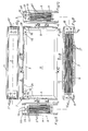
- the device 1 is made a narrow peripheral frame 2a of an outer casing 2, consisting of a total of two longitudinal frame sides 3, 4 and two narrow frame sides 5, 6 composed.
- On the bottom Longitudinal side 4 is that of Figures 13 to 17 and 20th and 21 apparent inner housing 7 elevated and thus over screws to be described firmly screwed.
- All frame sides 3, 4, 5, 6 are at their end portions Mitred cut and inserted there in 15 in Connection with screws 16 (see Fig. 1) to a circumferential, closed frame 2a connected.
- the From Figures 18 and 19 apparent light-emitting diodes 17 with their Control semiconductors and their boards by means of a thermally conductive, Double-sided adhesive, not shown here on film Heatsink 18 set of an aluminum alloy. hereby arise strip LED modules 19. Between the not shown, because not visible board and the heat sinks 18th are the heads of screws 20 inserted, which with their Screw shaft penetrate the heat sink 18 in openings and protrude beyond the outer surface, as it is the figures 18 and 19 can be removed.
- the LED modules 19 with the same joints 21 and Therefore, the same way over the coupling tabs 22 means Screws 23 to a compact support plate 24 with each other screwed.
- On in the corner regions of the support plate 24th located screws 20 are small cylinder 27 with Screwed internal thread, which thereby a Coupling pin 28 for a yet to be described Form plug connection.
- the holes 32 are in the cubic coupling elements 33 in the lower Corner areas formed as slots.
- angles 15 in the two lower corner areas can fastened with their horizontal legs by screws 34 be at the same time in the associated coupling elements 33rd engage in a retaining manner (see Fig. 13).
- angles 36 be by means of an adhesive, not shown on the Corner areas glued and thus block each unauthorized User access to the screws 16 and 35.
- angles 36 To release be the angles 36 in a workshop with a single Hammer hit off and then in reverse order the inner housing 7 from the outer housing 2 by loosening the Screw 16, 35 dismantled without an inner part of the Inner housing 7 or the outer housing 2 must take damage.
- the power supply 40 and the control computer 41 shown as a block, because whose items are not of interest here.
- the power supply 40 and the control computer 41 can both directly on the heat sinks 18th the LED modules 19 as well as on a separate Carrier plate 42, 43 are arranged to over this Carrier plate 42, 43 a corresponding heat dissipation to the four frame sides 3 to 6 of the outer housing 2 with the Cooling fins 37 ensure what is not the subject of this Invention is.
- the gist of the invention may be summarized as follows: By creating a book like a book as a plug-in unit designed inner housing 7 in an outer housing 2 may be a compact design can be maintained. At the same time both the Inner housing 7 and the outer housing 2 non-destructive in their Parts are disassembled without any of the components doing damage takes.
- each one here used LED modules 19 existing heat sink as a support frame Not only can a compact mounting plate 24, but also one compared to conventional LED modules with separate Mounting plates can be ensured even lighter version, because the previously required mounting plates are missing. And finally access to the screws 16 and 35 in the corner areas by the glued angle 36 an unauthorized user locked, but this does not complicate the dismantling.
Landscapes
- Business, Economics & Management (AREA)
- Accounting & Taxation (AREA)
- Marketing (AREA)
- Physics & Mathematics (AREA)
- General Physics & Mathematics (AREA)
- Engineering & Computer Science (AREA)
- Theoretical Computer Science (AREA)
- Casings For Electric Apparatus (AREA)
- Traffic Control Systems (AREA)
Abstract
Description
Die Erfindung betrifft eine Vorrichtung mit dynamischer LED-Anzeige für den Außen- oder Innenbereich mit einem Gehäuse mit einseitiger oder beidseitiger LED-Anzeige und einem darin angeordneten Steuerrechner und einem Netzteil, insbesondere für den öffentlichen Personennahverkehr, wobei ein umlaufender schmaler Rahmen des Gehäuses von zwei transparenten Scheiben abgedeckt ist und die mit Steuerhalbleitern in Verbindung stehenden LED-Module auf einer Halterungsplatte befestigt sind.The invention relates to a device with dynamic LED display for outdoor or indoor use with a housing with single-sided or double-sided LED display and one in it arranged control computer and a power supply, in particular for the public transport, being a circulating narrow frame of the case of two transparent panes is covered and related to control semiconductors LED modules are mounted on a mounting plate.
Dabei ist unter dem "Außenbereich" ein Einbauort zu verstehen, der grundsätzlich der Außenatmosphäre ausgesetzt und unter dem "Innenbereich" ein solcher Einbauort verstanden wird, der dem Einfluß der Außenatmosphäre mit seiner Anordnung in Innenräumen von Gebäuden oder Fahrzeugen entzogen ist.In this case, an installation location is under the "outdoor area" Understand, basically exposed to the outside atmosphere and Under the "interior" such a location is understood, the the influence of the external atmosphere with its arrangement in Interiors of buildings or vehicles is withdrawn.
Eine bekannte Vorrichtung dieser Art gemäß der DE 102 07 264 C 1 hat zwar die in sie gesetzten Erwartungen voll erfüllt, jedoch hat sich bei einer Reparatur als nachteilig herausgestellt, daß dann eine der beiden wasserdicht aufgeklebten Klarsichtscheiben nicht zerstörungsfrei entfernt werden kann, wobei auch die dieser Scheibe zugekehrte LED-Anzeige in Mitleidenschaft gezogen wird. Denn bei dieser Vorrichtung wird auf einen umlaufenden, geschlossenen Rahmen als Gehäuseteil an einer oder an beiden Rahmenseiten je eine vollflächige LED-Anzeigetafel als weiteres Gehäuseteil mittels einer doppelseitig klebenden, dünnen, strominsolierenden sowie wärmeleitenden Transparentfolie wasserdicht aufgeklebt. Dieser Kleber hat sich als derart werkstoffverbindend herausgestellt, daß ein zerstörungsfreies Öffnen des Gehäuses durch Entfernung einer LED-Anzeigetafel nicht möglich ist. Und schließlich hat sich bei dieser Vorrichtung als nachteilig der erhebliche Lageraufwand herausgestellt, weil stets nur komplette Vorrichtungen auf Lager gelegt werden konnten, da allein die auf den LED-Anzeigetafeln mittels der doppelseitig klebenden Transparentfolie aufgeklebten Klarsichtscheiben mit einer Abbindezeit des Klebers von zwei Tagen behaftet sind und nur stets fertige, nicht mehr veränderbare Vorrichtungen auf Lager gelegt werden konnten.A known device of this kind according to the Although DE 102 07 264 C1 has the expectations placed in it full fulfilled, however, has in a repair as disadvantageous proved that then one of the two glued waterproof Transparent windows can not be removed non-destructively, taking also the LED display facing this disc affected is pulled. Because in this device is on a encircling, closed frame as a housing part on one or on both sides of the frame each a full-surface LED display panel as further housing part by means of a double-sided adhesive, thin, Strominsolierenden and thermally conductive transparent film glued waterproof. This glue has turned out to be that way Materialverbindend exposed that a non-destructive opening of the enclosure by removing an LED display panel is possible. And finally, this device has as disadvantageous exposed the considerable storage costs, because always only complete devices could be stored in stock, as alone on the LED display panels by means of double-sided adhesive Transparency glued on transparent panels with a Setting time of the glue are subject to two days and only ever put finished, no longer changeable devices in stock could become.
Aus der DE 298 19 742 U 1 ist eine weitere Vorrichtung der eingangs genannten Gattung offenbart, bei welcher in einem im Querschnitt trapezoedalen Gehäuse Bauelemente, wie Leuchtdioden, Schaltungsplatinen, Energiequellen, Stromversorgung und weitere mechanische und elektrotechnische Komponenten angeordnet sind, wie sie üblicherweise für Verkehrsinformations-Anzeigen/Displays eingesetzt werden. Das Gehäuse wird an beiden Seiten von einer transparenten Abdeckeinrichtung verschlossen. Diese Abdeckeinrichtung, die bei einer bekannten, tatsächlichen Ausführungsform dieser Vorrichtung mittels am Gehäuseoberrand angebrachter Scharniergelenke abklappbar gestaltet ist, besteht aus einer äußeren Oberfläche und einer inneren Anzeigefläche. Die äußere Oberfläche ist mit einem Farbfilm aus geschmolzenem Glas versehen. Die innere Anzeigefläche besteht aus einer Schicht oder einem Film aus transparentem Material aus eingeschmolzenem Glas. Die innere Anzeigefläche ist von einem umlaufenden, lichtundurchlässigen Rahmen als Passepartout eingefaßt. Dadurch verkleinert sich zwangsläufig die Anzeigefläche der Abdeckeinrichtung zu den im Gehäuse angeordneten Leuchtdioden. Das Gehäuse ist äußerst voluminös. Bei einer Reparatur muß die Abdeckeinrichtung hochgeklappt oder sonstwie entfernt werden, um zu Reparaturzwecken einen Zugang zum Innenraum des Gehäuses zu schaffen. Als kritisch erweist sich dabei insbesondere die erneute Abdichtung der Abdeckeinrichtung am Gehäuse gegenüber Niederschlägen. Nach einer Wiederanbringung der Abdeckeinrichtung als Verschluß des Gehäuses muß keineswegs eine Dichtheit des Gehäuses gegeben sein.From DE 298 19 742 U 1 is a further device of discloses at the beginning of the type mentioned, in which in an im Cross-section of trapezoidal housing components, such as light-emitting diodes, Circuit boards, power sources, power and more mechanical and electrical components are arranged, as commonly used for traffic information displays / displays be used. The housing is on both sides of a closed transparent cover. These Covering device, which in a known, actual Embodiment of this device by means of the upper edge of the housing mounted hinged joints designed hinged, consists of an outer surface and an inner display surface. The outer surface is covered with a color film of molten glass Mistake. The inner display surface consists of a layer or a film of transparent material made of melted glass. The inner display area is of a circumferential, opaque frame framed as passepartout. Thereby inevitably reduces the display area of the Covering device to the light-emitting diodes arranged in the housing. The case is extremely bulky. In a repair must Cover device folded up or otherwise removed to for repair purposes access to the interior of the housing to accomplish. In particular, the renewed proves to be critical Sealing of the cover on the housing opposite Rainfall. After a replacement of the cover As a closure of the housing must by no means a tightness of the Be given housing.
Von diesem nächstkommenden Stand der Technik ausgehend, liegt der Erfindung die Aufgabe zugrunde, eine Vorrichtung der eingangs genannten Gattung zu schaffen, die unter Beibehaltung einer geringen Bautiefe sowie einer effektiven Wasserdichtheit gleichwohl einen zerstörungsfreien Zugang zum Innenraum, beispielsweise zu Reparaturzwecken, ebenso gewährleistet wie eine sichere statische Halterung der LED-Module sowie einen erheblich verringerten Lageraufwand.Starting from this closest state of the art, the invention has the object, a device of to create the aforementioned type, while maintaining a small depth and an effective waterproofness nevertheless a non-destructive access to the interior, For example, for repair purposes, as guaranteed as a secure static mounting of the LED modules as well as a considerable reduced storage costs.
Diese Aufgabe wird in Verbindung mit dem eingangs genannten
Gattungsbegriff erfindungsgemäß durch folgende Merkmale gelöst,
Damit wird in Abkehr von dem komplett geschlossenen Gehäuse gemäß der DE 102 07 264 C1, bei welchem die LED-Module mit über eine Transparentfolie mit einer Klarsichtscheibe verklebt sind, nunmehr dieses einteilige in ein zweiteiliges Gehäuse aufgelöst, bei welchem das Innengehäuse auf der vierten Rahmenseite - das ist in der Regel die untere Seite des Außengehäuses - aufgeständert ist und als Einschubeinheit in das Außengehäuse eingeschoben wird.This is in departure from the completely closed Housing according to DE 102 07 264 C1, in which the LED modules glued over a transparent film with a transparent panel are now dissolved this one-piece in a two-part housing, in which the inner housing on the fourth frame side - that is usually the lower side of the outer housing - is elevated and is inserted as a plug-in unit in the outer housing.
Zwischen dem von den kompakten Halterungsplatten der LED-Module gebildeten Innengehäuse werden der Steuerrechner und das Netzteil angeordnet.Between the compact mounting plates of the LED modules formed inner housing become the control computer and the power supply arranged.
Außerdem kann mit diesem Erfindungskonzept nunmehr der bisherige Lageraufwand drastisch dadurch verringert werden, daß nur unbestückte Außengehäuse ohne aufgeständerte Innengehäuse gelagert werden können und je nach Bedarf und Kundenwunsch sozusagen in Windeseile das Innengehäuse zusammengestellt, aufgeständert und die gesamte Vorrichtung fertiggestellt werden kann.In addition, with this inventive concept now the previous storage costs are drastically reduced by the fact that only unpopulated outer housing without elevated inner housing can be stored and as needed and customer request so to speak put together the inner casing at lightning speed, elevated and completed the entire device can.
Nach einer vorteilhaften Weiterbildung der Erfindung ist das Innengehäuse mit zwei LED-Anzeigetafeln in Form der Halterungsplatten für jede der beiden transparenten Scheiben des Außengehäuses versehen, die an mindestens ihren vier Eckenbereichen einen Kupplungszapfen aufweisen, mit denen sie an ihren beiden gegenüberliegenden Seiten lösbar in ein als Distanzhalter ausgebildetes Kupplungselement gesteckt sind. Dadurch können die kompakten Halterungsplatten des Innengehäuses mittels einer einfachen Steckverbindung in Form eines als Kupplungselement ausgebildeten Würfels miteinander gekuppelt werden. Um bei größeren Platteneinheiten eine Durchbiegung im Innenraum zu unterbinden, werden dann diese oder ähnliche Kupplungselemente auch im Innenraum zwischen den beiden Platteneinheiten angeordnet.According to an advantageous embodiment of the invention that is Inner housing with two LED display panels in the form of the Mounting plates for each of the two transparent panes of the Exterior housing provided on at least their four Corner areas have a coupling pin with which they to its two opposite sides detachable in one as Spacer trained coupling element are inserted. This allows the compact mounting plates of the Inner housing by means of a simple plug-in form a cube designed as a coupling element with each other be coupled. For larger disk units a To prevent deflection in the interior, then this or similar coupling elements in the interior between the arranged two disk units.
Im Zwischenraum zwischen den beiden Halterungsplatten ist vorteilhaft auf je einer mit den Halterungsplatten und/oder mit den Rahmenseiten des Außengehäuses verbundenen Trägerplatte einmal das Netzteil und einmal der Steuerrechner angeordnet.In the space between the two mounting plates is advantageous to one each with the support plates and / or with the Frame sides of the outer housing connected support plate once the power supply and once the control computer arranged.
Nach einer besonders vorteilhaften Weiterbildung der Erfindung sind die LED-Module sowie ihre Steuerhalbleiter mittels einer wärmeleitenden, doppelseitig klebenden Folie mit einer Platine auf Kühlkörpern befestigt, die über in letztere eingelassene und daran gehalterte Gewindebolzen und Kupplungslaschen mit gleicher Fuge miteinander zu einer kompakten Halterungsplatte verschraubt sind.After a particularly advantageous development of Invention, the LED modules and their control semiconductors means a thermally conductive, double-sided adhesive film with a board mounted on heat sinks, which are embedded in the latter and attached to it threaded bolt and coupling tabs with the same Groove bolted together to form a compact mounting plate are.
Damit wird eine zusätzliche Halterungsplatte, wie beispielsweise beim Gegenstand des DE 298 19 742 U1, dadurch entbehrlich, daß die Kühlkörper der LED-Module selbst mit den Verbindungslaschen zu einem Halterungsgerüst umfunktioniert werden, indem in diese Kühlkörper Gewindebolzen eingelassen sind, die mit ihren Schraubflächen aus der Oberfläche der Kühlkörper hinausragen und dort durch Kupplungslaschen fugengleich miteinander zu einer kompakten Halterungsplatte verschraubt sind. Dadurch können durch beliebige Aneinanderreihung der LED-Module diese an ihrer Kühlkörperseite zu relativ langen und breiten LED-Anzeigetafeln zusammengeschraubt werden. Diese spezielle Ausbildung hat zudem noch den Vorteil, daß die mit dem Netzteil und dem Steuerrechner verbundenen Trägerplatten ebenfalls aus Metall gefertigt werden und mit den aus einer Aluminiumlegierung bestehenden Kühlkörpern zur Wärmeableitung der Wärmemengen sowohl von den LED-Modulen als auch denen vom Netzteil und Steuerrechner benutzt werden und zur Sicherstellung eines entsprechend großen Wärmemengentransportes mit den metallischen Rahmenseiten des Außengehäuses wärmeleitend verbunden werden.This will add an extra bracket plate, such as For example, in the subject of DE 298 19 742 U1, thereby dispensable that the heat sink of the LED modules themselves with the Connecting straps converted into a mounting frame be by in this heat sink threaded bolts are embedded, the with their screw surfaces from the surface of the heat sink protrude and there by joints equal joints are bolted together to form a compact mounting plate. This can be done by any stringing together of the LED modules these on their heat sink side to relatively long and wide LED scoreboards are bolted together. This special Training also has the advantage that with the power supply and the control computer connected carrier plates also off Metal are made and made with an aluminum alloy existing heat sinks for heat dissipation of heat from both the LED modules and those of the power supply and Control computer can be used and to ensure a correspondingly large thermal mass transport with the metallic ones Frame sides of the outer housing are thermally conductively connected.
Nach einer vorteilhaften Weiterbildung der Erfindung ist die vierte Rahmenseite mit den angrenzenden Rahmenenden des Außengehäuses über Senkschrauben und einem Innengewinde sowie einem Kupplungselement verbunden, und die Schrauben sind von mittels eines Zweikomponentenklebers aufgeklebten Metallwinkeln abgedeckt, um so einen unbefugten Zugriff zu unterbinden. Zugleich vermittelt das Außengehäuse dem unbefangenen Betrachter ein Bild eines nicht zu öffnenden Außengehäuses.According to an advantageous embodiment of the invention is the fourth frame side with the adjacent frame ends of the Outer housing via countersunk screws and a female thread as well connected to a coupling element, and the screws are of by means of a two-component adhesive glued metal angles covered to prevent unauthorized access. at the same time The outer housing gives the unbiased viewer a picture a non-openable outer casing.
Drei Rahmenseiten des Außengehäuses sind an ihren auf Gehrung geschnittenen Seitenenden entweder zusammengeklebt oder unter Zwischenlegung einer Dichtung über einen Innenwinkel mit Schrauben verbunden. Bei einer Verbindung der Seitenenden mit Schrauben sind diese als Senkschrauben ausgebildet und werden gleichfalls von einem aufgeklebten Metallwinkel abgedeckt. Bei einer Klebung der Rahmenseiten des Außengehäuses werden die beiden zusätzlichen Winkel und Schrauben sowie ihre Schraubbohrungen entbehrlich, hingegen gestattet die komplette Verschraubung auch das Auswechseln einiger Rahmenseiten.Three frame sides of the outer housing are at their on Miter cut side ends either glued together or with the interposition of a seal with an internal angle with Screws connected. When connecting the footers with These screws are designed as countersunk screws and are also covered by a glued metal angle. At a Bonding of the frame sides of the outer housing are the two additional angles and screws as well as their screw holes dispensable, however, allows the complete screwing also the replacement of some frame pages.
Nach einer besonders vorteilhaften Weiterbildung der Erfindung sind die Kupplungselemente zwischen den beiden kompakten Halterungsplatten der LED-Module in der Nähe der vierten Rahmenseite mit dieser zu einer festen Schubeinheit verschraubt. Vorteilhaft sind auch an den von der vierten Rahmenseite des Außengehäuses abgewandten Eckenbereichen des Innengehäuses Kupplungselemente zwischen den beiden kompakten Halterungsplatten vorgesehen, an welchen die Eckenbereiche über Kupplungszapfen gehaltert sind.After a particularly advantageous development of Invention are the coupling elements between the two compact mounting plates of the LED modules near the fourth frame side with this to a fixed push unit screwed. Also advantageous are those of the fourth Frame side of the outer housing facing away from the corners of the Inner housing coupling elements between the two compact Mounting plates provided on which the corner areas over Hitch pins are held.
Als lösbares Dichtungsmittel ist zwischen der vierten Rahmenseite und den angrenzenden Kanten der transparenten Scheiben sowie den angrenzenden Rahmenenden des Außengehäuses ein Silikonstreifen vorgesehen. Um auch die im Innengehäuse vorhandenen Teile leicht voneinander trennen zu können, sind das Netzteil und der Steuerrechner im Innengehäuse über lösbare elektrische Steckkupplungen miteinander, mit den LED-Modulen sowie mit weiteren Einbaukomponenten, wie Minikameras, Sensoren, Empfangs-Sendeeinheiten, Lautsprechern und Mikrofonen, verbunden.As a releasable sealant is between the fourth Frame side and the adjacent edges of the transparent Washers and the adjacent frame ends of the outer housing a silicone strip provided. In order also in the inner housing It is easy to separate existing parts from each other Power supply and the control computer in the inner housing via detachable electrical plug-in couplings with each other, with the LED modules and with other built-in components, such as miniature cameras, sensors, Reception units, loudspeakers and microphones, connected.
Zur kontrastreichen Wiedergabe der LED-Anzeige sind die transparenten Scheiben des Außengehäuses auf ihrer Innenseite mit einer transparenten Farbfolie belegt. Außerdem sind sie auf ihrer Außenseite mit einem Zweikomponenten-Glaslack versehen, um einerseits kontrastschärfere Konturen der LED-Anzeige zu gewährleisten, und andererseits wirkt nach einer überraschenden Feststellung des Erfmders dieser Glaslack wärmedämmend, insbesondere bei einem senkrechtem Auftreffen von Sonnenstrahlen.For high-contrast reproduction of the LED display are the transparent discs of the outer housing on its inside with a transparent color foil occupied. Besides, they are on theirs Outside provided with a two-component glass paint to on the one hand, contrast-sharp contours of the LED display ensure, on the other hand, after a surprising Determination of the Erfmders this glass varnish thermally insulating, especially with a vertical impact of sunbeams.
Die vierte, mit dem Innengehäuse lösbar gekuppelte
Rahmenseite, die gleichzeitig die Unterseite des Außengehäuses
bildet, ist mit zwei wasserdichten Steckdosen versehen, von denen
die eine in an sich bekannter Weise mit einer elektrischen
Datenversorgungsleitung und die andere mit einer elektrischen
Energieversorgungsleitung zu kuppeln ist, was grundsätzlich aus der
DE 102 07 264 C 1 bekannt ist.The fourth, with the inner housing detachably coupled
Frame side, which at the same time the underside of the outer housing
is provided with two watertight sockets, one of which
the one in a conventional manner with an electric
Data supply line and the other with an electrical
To couple power supply line is what basically from the
DE 102 07 264
Um die im Innengehäuse und im Innenraum des Außengehäuses entstehende Wärme abführen zu können, sind sämtliche Außenflächen der umlaufenden, aus einer Aluminiumlegierung bestehenden Rahmenseiten des Außengehäuses mit stoffschlüssig mit diesen Rahmenseiten verbundenen Rippen versehen. Diese Rippen werden von Luft umspült und somit durch Luftkonvektion sowie durch Wärmeabstrahlung gekühlt.To those in the inner casing and in the interior of the Outer housing heat to be dissipated, are all outer surfaces of the revolving, from one Aluminum alloy existing frame sides of the outer housing with cohesively connected with these frame sides ribs Mistake. These ribs are lapped by air and thus by Air convection and cooled by heat radiation.
Diese Rahmenseiten des Außengehäuses bestehen vorteilhaft aus einer Aluminiumlegierung.These frame sides of the outer housing are advantageous from an aluminum alloy.
Das Außengehäuse wird vorteilhaft über eine Schraub- oder
Steckverbindung lösbar an einer Halterung befestigt, sei es an einem
Galgen oder innerhalb einer Informationssäule oder sonstigen
Halterungen, wie sie beispielsweise in der DE 102 07 264 C 1
dargestellt ist. The outer housing is advantageous via a screw or
Plug-in connection releasably attached to a holder, be it on one
Gallows or within an information column or other
Mounts, as described for example in DE 102 07 264
Ein Ausführungsbeispiel der Erfindung ist in allen Einzelheiten
in den Zeichnungen dargestellt. Dabei zeigen:
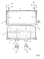
Gemäß den Figuren 1 bis 5 besteht die Vorrichtung 1 aus
einem schmalen umlaufenden Rahmen 2a eines Außengehäuses 2,
der sich aus insgesamt zwei Längsrahmenseiten 3, 4 sowie zwei
schmalen Rahmenseiten 5, 6 zusammensetzt. Auf der unteren
Längsrahmenseite 4 ist das aus den Figuren 13 bis 17 sowie 20
und 21 ersichtliche Innengehäuse 7 aufgeständert und damit über
noch zu beschreibende Schrauben fest verschraubt.According to the figures 1 to 5, the
Ferner sind an der unteren Rahmenseite 4 zwei wasserdichte
Steckdosen 8, 9 angeordnet, von denen eine mit einer elektrischen
Datenversorgungsleitung und die andere mit einer elektrischen
Energieversorgungsleitung zu kuppeln ist.Further, at the
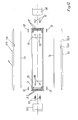
Auf die Rahmenseiten 5, 3, 6 ist beidseitig gemäß den
Figuren 6 bis 10 je eine transparente Scheibe 10, 11 mit den aus den
Figuren 11 und 12 ersichtlichen Dichtungsstreifen 12 aufgeklebt.
Außerdem sind auf den Innenflächen 10a, 11a der beiden
transparenten Scheiben 10, 11 transparente Farbfolien 13, 14
aufgeklebt. Die Farbfolien 13, 14 sind meistens rot, können jedoch
auch in anderen Farben, Grau, Grün, Gelb oder Blau, hergestellt
sein. Die Außenflächen 10b, 11b der transparenten Scheiben 10, 11
sind mit einem Glaslack versehen.On the frame sides 5, 3, 6 is on both sides according to the
Figures 6 to 10 each have a
Sämtliche Rahmenseiten 3, 4, 5, 6 sind an ihren Endbereichen
auf Gehrung geschnitten und über dort eingelegte Innenwinkel 15 in
Verbindung mit Schrauben 16 (s. Fig. 1) zu einem umlaufenden,
geschlossenen Rahmen 2a verbunden.All frame sides 3, 4, 5, 6 are at their end portions
Mitred cut and inserted there in 15 in
Connection with screws 16 (see Fig. 1) to a circumferential,
closed
Zunächst wird gemäß den Figuren 6 bis 10 das
Außengehäuse 2 über die Innenwinkel 15 und die Schrauben 16 zu
einem U-förmigen Rahmen und nach Aufklebung der transparenten
Scheiben 10, 11 mit ihren farbigen Folien 13, 14 zu einem
Einschubgehäuse als Außengehäuse 2 vervollständigt. Auf die vierte
Rahmenseite 4 (s. Figuren 1 und 13) wird das in den Figuren 13
bis 17 dargestellte Innengehäuse 7 wie folgt aufgeständert:First, according to FIGS. 6 to 10, the
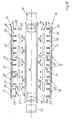
In einem ersten Montage- bzw. Fertigungsschritt werden die
aus den Figuren 18 und 19 ersichtlichen Leuchtdioden 17 mit ihren
Steuerhalbleitern und ihren Platinen mittels einer wärmeleitenden,
doppelseitig klebenden, hier nicht dargestellten Folie auf
Kühlkörper 18 aus einer Aluminiumlegierung gesetzt. Hierdurch
entstehen streifenförmige LED-Module 19. Zwischen der nicht
dargestellten, weil nicht sichtbaren Platine und den Kühlkörpern 18
sind die Köpfe von Schrauben 20 eingelassen, die mit ihrem
Schraubschaft die Kühlkörper 18 in Öffnungen durchdringen und
über deren Außenfläche vorstehen, so, wie es den Figuren 18 und 19
entnommen werden kann. In a first assembly or manufacturing step, the
From Figures 18 and 19 apparent light-emitting
Sodann werden die LED-Module 19 mit gleichen Fugen 21 und
daher fugengleich über die Kupplungslaschen 22 mittels
Schrauben 23 zu einer kompakten Halterungsplatte 24 miteinander
verschraubt. Dadurch entsteht auf der Außenfläche 25 der
kompakten Halterungsplatte 24 ein gleichmäßiges Raster von
Leuchtdioden 17 und auf der Innenseite 26 einer jeden
Halterungsplatte 24 ein zusammenhängendes Traggerüst, welches
von der Summe der Kühlkörper 18 der einzelnen LED-Module 19
gebildet ist. Auf die in den Eckenbereichen der Halterungsplatte 24
befindlichen Schrauben 20 werden kleine Zylinder 27 mit
Innengewinde geschraubt, welche dadurch einen
Kupplungszapfen 28 für eine noch zu beschreibende
Steckverbindung bilden.Then, the
Um eine Durchbiegung einer der beiden vorbeschriebenen
kompakten Halterungsplatten 24 in ihren Mittenbereichen zu
unterbinden, befinden sich auch - wie aus Fig. 18 ersichtlich ist - in
diesem Mittenbereich die vorbeschriebenen Schraubbolzen 20 und
werden dort über breite Muttern 29 mit einem Schraubbolzen 30
sowie Kontermuttern 31 zu einem Abstandshalter mit
Halterungsfunktion zusammengefügt.To a deflection of one of the two above
Nachdem die kompakten Halterungsplatten 24 gemäß den
Figuren 18 und 19 zusammengefügt worden sind, werden sie mit
ihren Kupplungsbolzen 28 an allen vier Eckenbereichen in eine
Ausnehmung 32 eines würfelförmigen Kupplungselementes 33
gesteckt und dadurch lösbar gekuppelt sowie gleichmäßig distanziert.
Die in Fig. 13 in den unteren beiden Eckenbereichen befindlichen
Kupplungselemente 33 sind vorteilhaft, aber nicht unbedingt mit je
einem Langloch als Öffnung 32 versehen, um eine Ausrichtung zu
ermöglichen.After the
Wie aus den Figuren 1 und 13 entnommen werden kann, sind
die würfelförmigen Kupplungselemente 33 in den unteren beiden
Eckenbereichen über mindestens eine Schraube 16 sowohl mit dem
Innenwinkel 15 als auch mit der vierten Rahmenseite 4 fest
verbunden. Dadurch sind die beiden kompakten
Halterungsplatten 24 auf der vierten Rahmenseite 4 des
Außengehäuses 2 aufgeständert und können so gemäß den
Figuren 20 und 21 in das gemäß den Figuren 6 bis 10 vorgefertigte
Einschubteil des Außengehäuses 2 wie ein Buch eingeschoben
werden. Vor dem Einschub werden gemäß Fig. 11 die lösbaren
Dichtungsmittel 12a auf die Dichtungsstreifen 12 aufgetragen, um
auch die vierte Rahmenseite 4 spritzwasserdicht mit den
angrenzenden Rahmenteilen des Außengehäuses 2 zu verbinden.
Nach dem Einschub werden die in den beiden oberen Eckenbereichen
befindlichen Kupplungselemente 33 von je einer Schraube 35 fest
gegen die obere Rahmenseite 3 des Außengehäuses 2 gezogen und
damit verbunden. Ebenso wird der nach oben weisende Schenkel der
Winkel 15 in den beiden unteren Eckenbereichen mit zwei
Schrauben 16 an jeder Seite der kleinen Rahmenseiten 5 bzw. 6
und/oder gleichfalls mit einer langen Schraube 35 an der langen
Rahmenseite 4 festgeschraubt. Zur Ausrichtung sind die Löcher 32 in
den würfelförmigen Kupplungselementen 33 in den unteren
Eckenbereichen als Langlöcher ausgebildet.As can be seen from Figures 1 and 13, are
the cube-shaped
Die Winkel 15 in den beiden unteren Eckenbereichen können
mit ihren horizontalen Schenkeln auch durch Schrauben 34 befestigt
werden, die zugleich auch in die zugeordneten Kupplungselemente 33
halternd eingreifen (s. Fig. 13).The
Nachdem in allen vier Eckenbereichen des Innengehäuses 2 die
würfelförmigen Kupplungselemente 33 und damit das
Innengehäuse 7 im Außengehäuse 2 durch die Schrauben 16, 35
festgesetzt sind, werden die von außen sichtbaren Köpfe der
Senkschrauben 16, 35 durch Winkel 36 abgedeckt. Diese Winkel 36
werden mittels eines nicht dargestellten Klebemittels auf die
Eckenbereiche geklebt und versperren somit jedem unbefugten
Benutzer einen Zugriff zu den Schrauben 16 und 35. Zum Lösen
werden die Winkel 36 in einer Werkstatt mit einem einzigen
Hammerschlag abgeschlagen und sodann in umgekehrter Reihenfolge
das Innengehäuse 7 vom Außengehäuse 2 durch Lösen der
Schrauben 16, 35 demontiert, ohne daß ein Innenteil des
Innengehäuses 7 oder des Außengehäuses 2 Schaden nehmen muß.After in all four corners of the
Wie außerdem aus nahezu sämtlichen Figuren hervorgeht, sind
die Außenflächen der Rahmenteile 3 bis 6 mit Rippen 37 versehen,
die besonders deutlich aus den Figuren 7, 11, 12, 16, 17, 18 und 20
ersichtlich sind. Die Rippen 37 sind nur in den Eckenbereichen zur
planen Auflage der Außenabdeckwinkel 36 ausgespart, wie am
anschaulichsten den Figuren 2 bis 5 entnommen werden kann. Diese
Rippen 37 tragen aufgrund ihrer die Außenflächen der
Rahmenseiten 3 bis 5 vergrößernden Flächen zu einer besseren
Kühlung durch Luftkonvektion sowie durch Abstrahlung bei.As also evident from almost all figures, are
the outer surfaces of the
Aus Fig. 21 ist ersichtlich, daß die wasserdichten
Steckdosen 8, 9 mit entsprechend wasserdichten
Kupplungssteckern 38, 39 zu kuppeln sind, von denen einer mit
einer elektrischen Datenversorgungsleitung und der andere mit einer
elektrischen Energieversorgungsleitung verbunden ist.From Fig. 21 it can be seen that the
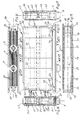
In den Figuren 13, 16, 17 und 20 des Innengehäuses 7 sind
das Netzteil 40 und der Steuerrechner 41 als Block dargestellt, weil
deren Einzelteile hier nicht weiter interessieren. Das Netzteil 40 und
der Steuerrechner 41 können sowohl direkt auf den Kühlkörpern 18
der LED-Module 19 als auch auf einem getrennten
Trägerblech 42, 43 angeordnet werden, um über dieses
Trägerblech 42, 43 einen entsprechenden Wärmeabtransport zu den
vier Rahmenseiten 3 bis 6 des Außengehäuses 2 mit den
Kühlrippen 37 sicherzustellen, was jedoch nicht Gegenstand dieser
Erfindung ist.In the figures 13, 16, 17 and 20 of the
Der Kern der Erfindung darf wie folgt zusammengefaßt werden:
Durch Schaffung eines wie ein Buch als Einschubeinheit
ausgestalteten Innengehäuses 7 in ein Außengehäuse 2 kann eine
kompakte Bauweise beibehalten werden. Zugleich können sowohl das
Innengehäuse 7 als auch das Außengehäuse 2 zerstörungsfrei in ihre
Einzelteile zerlegt werden, ohne daß eines der Bauteile dabei Schaden
nimmt. Durch die elegante Ausnutzung der bei jedem der hier
verwendeten LED-Module 19 vorhandenen Kühlkörper als Traggerüst
kann nicht nur eine kompakte Halterungsplatte 24, sondern auch
eine gegenüber herkömmlichen LED-Modulen mit separaten
Montageplatten noch leichtere Ausführung sichergestellt werden, weil
die bislang obligatorischen Montageplatten fehlen. Und schließlich
wird der Zugang zu den Schrauben 16 und 35 in den Eckenbereichen
durch die aufgeklebten Winkel 36 einem unbefugten Benutzer
versperrt, jedoch dadurch die Demontage nicht erschwert. The gist of the invention may be summarized as follows:
By creating a book like a book as a plug-in unit
designed
Mit diesem Konzept wird eine Vorrichtung geschaffen, die trotz
ihrer Ausbildung als Einschubeinheit eines Innengehäuses 7 in ein
Außengehäuse 2 kompakt geblieben und dennoch zerstörungsfrei in
sämtliche Einzelteile zerlegbar ist. With this concept, a device is created, despite
their training as a plug-in unit of an
- Vorrichtungcontraption
- 11
- Außengehäuseouter casing
- 22
- Rahmenframe
- 2a2a
-
Längsseiten des Rahmens 2aLongitudinal sides of the
frame 2a - 3, 43, 4
- kurze Rahmenseitenshort frame pages
- 5, 65, 6
- Innengehäuseinner housing
- 77
- Steckdosensockets
- 8, 98, 9
- Scheibenslices
- 10, 1110, 11
-
Innenfläche der Scheiben 10, 11Inner surface of the
discs - 10a, 11a10a, 11a
-
Außenfläche der Scheiben 10, 11Outer surface of the
discs 10, 11th - 10b, 11b10b, 11b
- Dichtungsstreifenweatherstrip
- 1212
- lösbares Dichtungsmittelreleasable sealant
- 12a12a
- Farbfoliencolor films
- 13, 1413, 14
- Innenwinkelinterior angle
- 1515
- Schraubenscrew
- 16, 23, 34, 3516, 23, 34, 35
- LeuchtdiodenLEDs
- 1717
- Kühlkörperheatsink
- 1818
- LED-ModuleLED modules
- 1919
- Gewindebolzenthreaded bolt
- 2020
- FugenPut
- 2121
- Kupplungslaschencoupling brackets
- 2222
- Halterungsplattensupport plates
- 2424
-
Außenfläche der
Halterungsplatte 24Outer surface of the
Bracket plate 24 - 25 25
-
Innenseite der
Halterungsplatte 24Inside the
Bracket plate 24 - 2626
- Zylindercylinder
- 2727
- Kupplungszapfenkingpin
- 2828
- Mutternnuts
- 2929
- Schraubbolzenbolts
- 3030
- Kontermutternlocknuts
- 3131
- Ausnehmungrecess
- 3232
- Kupplungselementecoupling elements
- 3333
- Winkelangle
- 3636
- Kühlrippencooling fins
- 3737
- Kupplungssteckercoupling plug
- 38, 3938, 39
- Netzteilpower adapter
- 4040
- Steuerrechnertax calculator
- 4141
- Trägerblechsupport plate
- 42, 4342, 43
Claims (16)
Applications Claiming Priority (2)
| Application Number | Priority Date | Filing Date | Title |
|---|---|---|---|
| DE10339413 | 2003-08-27 | ||
| DE2003139413 DE10339413B3 (en) | 2003-08-27 | 2003-08-27 | Arrangement with dynamic LED display, especially for exteriors of public transport vehicles, has outer housing and inner housing formed by mounting boards for light emitting diode modules |
Publications (2)
| Publication Number | Publication Date |
|---|---|
| EP1510992A2 true EP1510992A2 (en) | 2005-03-02 |
| EP1510992A3 EP1510992A3 (en) | 2006-03-29 |
Family
ID=32864530
Family Applications (1)
| Application Number | Title | Priority Date | Filing Date |
|---|---|---|---|
| EP04019343A Withdrawn EP1510992A3 (en) | 2003-08-27 | 2004-08-14 | Dynamic graphic LED display device for outdoor use in public local passengers traffic |
Country Status (2)
| Country | Link |
|---|---|
| EP (1) | EP1510992A3 (en) |
| DE (1) | DE10339413B3 (en) |
Cited By (1)
| Publication number | Priority date | Publication date | Assignee | Title |
|---|---|---|---|---|
| CN112634760A (en) * | 2020-12-22 | 2021-04-09 | 上海冠凯软件技术有限公司 | Automatic change test tool data display device that models model |
Families Citing this family (1)
| Publication number | Priority date | Publication date | Assignee | Title |
|---|---|---|---|---|
| RU201096U1 (en) * | 2020-06-29 | 2020-11-26 | Виктор Людвигович Поляков | Monitor case-radiator |
Family Cites Families (3)
| Publication number | Priority date | Publication date | Assignee | Title |
|---|---|---|---|---|
| DE29819742U1 (en) * | 1998-10-01 | 1999-01-07 | Lumino Licht Elektronik GmbH, 47799 Krefeld | Device for displaying alpha-numeric and / or pictorial characters |
| DE10207264C1 (en) * | 2002-02-21 | 2003-06-26 | Line Elektro Electronic Gmbh E | Dynamic LED display for public transport vehicles and boarding points, has a narrow frame to support the display covered by a thin film and a transparent pane in a waterproof assembly linked to the control computer |
| DE20313263U1 (en) * | 2003-08-27 | 2003-11-13 | provi GmbH, 09661 Hainichen | Device with dynamic LED display, especially for the outside area of local public transport |
-
2003
- 2003-08-27 DE DE2003139413 patent/DE10339413B3/en not_active Expired - Fee Related
-
2004
- 2004-08-14 EP EP04019343A patent/EP1510992A3/en not_active Withdrawn
Cited By (1)
| Publication number | Priority date | Publication date | Assignee | Title |
|---|---|---|---|---|
| CN112634760A (en) * | 2020-12-22 | 2021-04-09 | 上海冠凯软件技术有限公司 | Automatic change test tool data display device that models model |
Also Published As
| Publication number | Publication date |
|---|---|
| DE10339413B3 (en) | 2004-09-16 |
| EP1510992A3 (en) | 2006-03-29 |
Similar Documents
| Publication | Publication Date | Title |
|---|---|---|
| DE69525664T2 (en) | Device for aligning display modules | |
| EP1346822A1 (en) | Roof element for buildings | |
| EP0676160B1 (en) | Device for displaying flat articles | |
| WO2009080758A1 (en) | Frame having integrated lighting and power supply | |
| DE19515122A1 (en) | TV transmitting and receiving equipment switch-cabinet e.g. for hot outdoor locations | |
| DE102014010278A1 (en) | Sectional | |
| DE19709460C2 (en) | Outdoor housing | |
| DE2160513A1 (en) | Unit building system - with pvc cover plates inserted in plastic profile rods and current profiles | |
| DE10339413B3 (en) | Arrangement with dynamic LED display, especially for exteriors of public transport vehicles, has outer housing and inner housing formed by mounting boards for light emitting diode modules | |
| DE20313263U1 (en) | Device with dynamic LED display, especially for the outside area of local public transport | |
| EP2834080B1 (en) | Composite glass with functional element | |
| DE10207264C1 (en) | Dynamic LED display for public transport vehicles and boarding points, has a narrow frame to support the display covered by a thin film and a transparent pane in a waterproof assembly linked to the control computer | |
| DE1932380A1 (en) | Circuit design | |
| DE212023000042U1 (en) | Retrofittable multifunctional display module | |
| EP3918175B1 (en) | Pane unit and method for producing and/or providing such a pane unit | |
| DE202010001914U1 (en) | Furniture component, in particular furniture floor, and furniture with furniture component | |
| DE20202684U1 (en) | Device with dynamic, fully graphic-capable LED display in the outside area of local public transport | |
| EP0908990A2 (en) | Information and communication installation | |
| DE2144752A1 (en) | ADVERTISING MEDIA | |
| DE102017115730A1 (en) | LED panel with swing-out connector | |
| DE102015102424A1 (en) | Method for producing at least a part of a piece of furniture or a piece of furniture and furniture or furnishing item | |
| DE202010016760U1 (en) | Frame for installation in openings of walls | |
| DE102023124355A1 (en) | Waterproof lighting device and method of making same | |
| DE20114958U1 (en) | Display device for stops | |
| DE19626613A1 (en) | Spacers |
Legal Events
| Date | Code | Title | Description |
|---|---|---|---|
| PUAI | Public reference made under article 153(3) epc to a published international application that has entered the european phase |
Free format text: ORIGINAL CODE: 0009012 |
|
| AK | Designated contracting states |
Kind code of ref document: A2 Designated state(s): AT BE BG CH CY CZ DE DK EE ES FI FR GB GR HU IE IT LI LU MC NL PL PT RO SE SI SK TR |
|
| AX | Request for extension of the european patent |
Extension state: AL HR LT LV MK |
|
| PUAL | Search report despatched |
Free format text: ORIGINAL CODE: 0009013 |
|
| AK | Designated contracting states |
Kind code of ref document: A3 Designated state(s): AT BE BG CH CY CZ DE DK EE ES FI FR GB GR HU IE IT LI LU MC NL PL PT RO SE SI SK TR |
|
| AX | Request for extension of the european patent |
Extension state: AL HR LT LV MK |
|
| AKX | Designation fees paid |
Designated state(s): AT BE BG CH CY CZ DE DK EE ES FI FR GB GR HU IE IT LI LU MC NL PL PT RO SE SI SK TR |
|
| 17P | Request for examination filed |
Effective date: 20060927 |
|
| GRAP | Despatch of communication of intention to grant a patent |
Free format text: ORIGINAL CODE: EPIDOSNIGR1 |
|
| 19U | Interruption of proceedings before grant |
Effective date: 20080131 |
|
| 19W | Proceedings resumed before grant after interruption of proceedings |
Effective date: 20081201 |
|
| RAP1 | Party data changed (applicant data changed or rights of an application transferred) |
Owner name: ISOTRONIC-SYSTEMS GMBH |
|
| GRAC | Information related to communication of intention to grant a patent modified |
Free format text: ORIGINAL CODE: EPIDOSCIGR1 |
|
| STAA | Information on the status of an ep patent application or granted ep patent |
Free format text: STATUS: THE APPLICATION IS DEEMED TO BE WITHDRAWN |
|
| 18D | Application deemed to be withdrawn |
Effective date: 20090415 |